
A cable assembly can pass continuity and still be the wrong RF part.
That situation appears more often than many buyers expect. The connector mates correctly, the cable length matches the drawing, and the first sample works during bench testing. Problems usually appear later: the assembly is installed into a tighter enclosure, routed around a metal frame, tested at a higher frequency, or produced in larger quantities with different termination conditions.
An RF cable assembly is not only a cable with two connectors attached. The complete RF path depends on the relationship between the coaxial cable, connector geometry, termination process, operating frequency, and inspection method.
For engineers and procurement teams, the key question is not simply “Can this cable connect?” It is “Will this assembly maintain the expected RF characteristics after installation and production?”
A practical RF cable assembly normally combines:
- Coaxial cable selected for impedance and frequency requirements
- RF connectors matched to the cable structure
- Proper crimping, soldering, or termination process
- Electrical inspection such as continuity, VSWR, insertion loss, or return loss testing when required
How Do RF Cable Assemblies Support Complete Signal Paths?
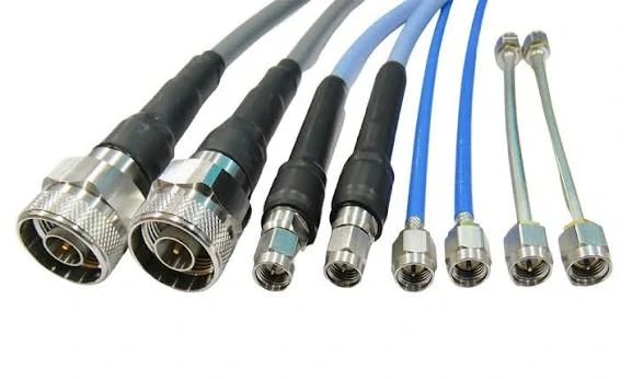
This image shows a customized RF cable assembly solution with different connector configurations. RF cable assemblies are designed by matching cable type, connector interface, frequency requirements, and application conditions.
Many RF projects start with separate components. An engineer selects a connector, chooses a coaxial cable, and later decides how everything should be assembled. This approach can work for prototypes, but it often creates problems when the design moves into production.
The reason is simple: RF performance is determined by the complete assembly, not individual parts.
A connector rated for 18 GHz does not automatically make every attached cable assembly suitable for 18 GHz operation. The cable type, cable diameter, dielectric material, shielding structure, connector transition, and assembly method all influence the final result.
For example, an SMA connector designed for a small flexible cable such as RG316 should not be replaced with an SMA connector designed for RG58 only because the front interface looks identical. The mating interface may fit, but the rear structure, ferrule size, and center pin design may not match the cable.
This is a common sourcing mistake. The connector specification sheet may look acceptable, but the actual assembly can fail during RF measurement because of mismatch, higher insertion loss, or inconsistent termination.
Why do RF systems need finished cable assemblies?
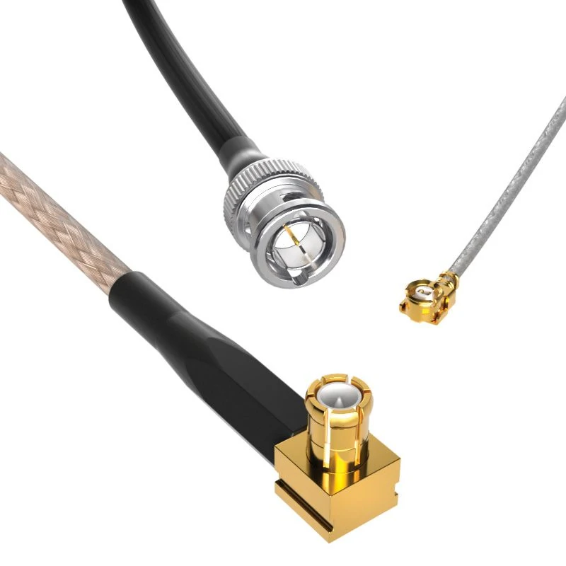
A BNC RF cable assembly includes BNC connectors and coaxial cable designed for stable signal transmission. Proper impedance matching and cable selection are important for RF measurement applications.
A finished RF cable assembly reduces uncertainty between design and installation.
Instead of purchasing cable and connectors separately, buyers can define the complete connection requirement:
- Connector A and Connector B
- Male, female, plug, or jack configuration
- Cable type and impedance
- Required length
- Operating frequency
- Application environment
- Testing requirements
This information allows the supplier to evaluate the complete RF path rather than only quoting individual components.
A prototype cable may only need to work once. A production RF cable assembly must work repeatedly across hundreds or thousands of units.
That difference changes the selection criteria.
RF Connection Solution Comparison
| Solution | Typical Application | Advantage | Limitation |
| Connector Only | Cable manufacturing or repair | Flexible component sourcing | Requires assembly process |
| RF Adapter | Interface conversion | Quick connection between standards | Adds additional transition points |
| RF Cable Assembly | Complete signal connection | Ready for installation | Fixed specification |
| Custom RF Assembly | OEM and special projects | Matches exact requirements | Requires technical input |
Adapters are useful when equipment interfaces do not match. For example, an SMA-to-N adapter can solve a temporary interface problem between laboratory equipment and antenna hardware.
However, every additional adapter introduces another RF transition. At low frequencies this may have little impact, but at higher frequencies the accumulated effect becomes more noticeable.
For permanent installations, many engineers prefer a direct cable assembly with the correct connector on each end.
How Should You Define RF Cable Assembly Requirements Before Ordering?
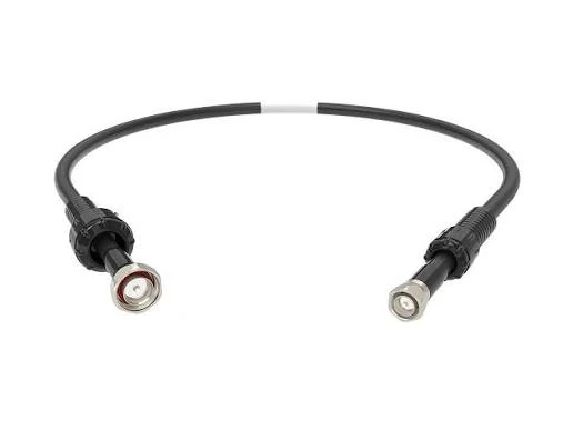
This SMA RF cable assembly uses flexible coaxial cable and SMA connectors. The final RF performance depends on connector compatibility, cable type, termination quality, and operating frequency.
A frequent purchasing issue is sending a supplier only a product name, such as “SMA cable” or “RF cable assembly.”
This description is usually not enough.
“SMA cable assembly” can refer to many different products:
- SMA male to SMA female
- SMA male to N female
- SMA right angle to SMA straight
- RG316 cable
- RG58 cable
- Low-loss microwave cable
- Different lengths and test requirements
The connector name describes only the interface. It does not define the complete RF assembly.
Specify connector-to-connector configuration first
Before production, define both ends of the assembly.
Important information includes:
- Connector A
- Connector B
- Gender
- Mounting style
- Straight or right-angle structure
- Standard or reverse polarity
For example, a BOM description such as:
SMA male to N female cable assembly, 50 ohm, RG316, 500 mm length, DC–6 GHz
provides much more useful information than:
SMA cable
The second description leaves too many decisions to the supplier.
Define cable specifications according to the application
The cable choice affects attenuation, flexibility, and installation reliability.
Key parameters normally include:
- Cable type
- Impedance
- Length
- Frequency range
A short internal connection inside an RF module may prioritize flexibility and small diameter. A cable running from an outdoor antenna to equipment may require lower attenuation and stronger mechanical protection.
The same connector family can be paired with different cable types depending on the application.
Prepare technical information for custom RF projects
Custom RF cable assemblies require more than a connector selection.
Useful information includes:
- Product drawing
- Existing sample
- Electrical requirements
- Quantity requirement
A supplier can usually provide a more accurate solution when the application information is clear.
The goal is not to add unnecessary specifications. The goal is to prevent the common situation where the sample works but the production version does not match the actual installation environment.
How Do Connector Choices Affect RF Cable Assembly Performance?
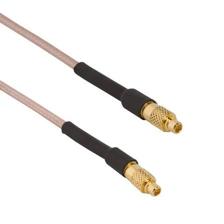
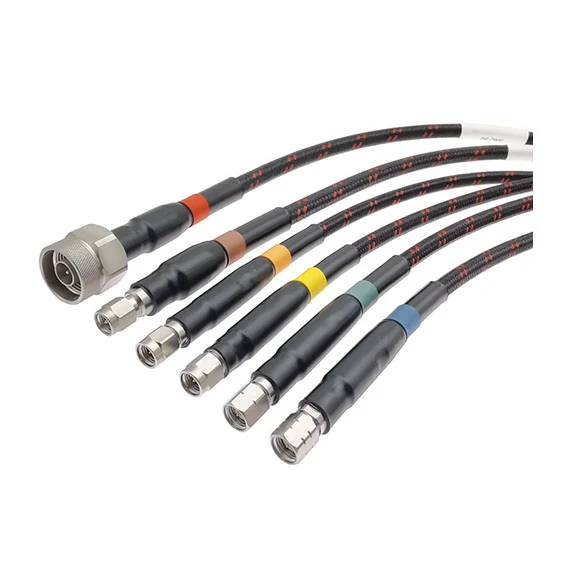
Multiple RF cable assemblies with different connector interfaces are shown. Microwave cable assemblies require careful control of cable structure, connector transition, and electrical testing.
A connector can fit the equipment port and still create problems inside the RF system.
The purchasing team finds a cable with the same connector name, the same impedance, and a similar frequency rating. The sample arrives, connects normally, and appears acceptable.
The problem starts when the cable is measured at the actual working frequency.
The connector interface is only one part of the RF path. The transition between connector and coaxial cable also affects the result. A poor match at this point can increase reflection, change VSWR, or create inconsistent results between batches.
For an RF cable assembly, engineers usually need to evaluate:
- Connector interface and gender
- Cable compatibility
- Frequency margin
- Termination method
- Mechanical stress after installation
- Required electrical testing
A connector should be selected together with the cable, not separately.
Why can two SMA cable assemblies produce different RF results?
This image shows RF cable assemblies using larger coaxial connectors such as N Type and TNC. These assemblies are suitable for applications requiring mechanical strength and stable RF performance.
SMA cable assemblies are widely used in compact RF equipment because the connector size is small and the interface is well established.
They appear in:
- Wireless modules
- GPS equipment
- RF boards
- Test fixtures
- Communication devices
However, “SMA cable assembly” is not a complete specification.
An SMA assembly using RG316 is not equivalent to an SMA assembly using RG58. The connector body may look similar, but the rear section, ferrule size, and termination structure are different.
This is one reason why a supplier usually needs the cable model before confirming a connector.
For example:
| Assembly Requirement | Possible Selection |
| Short internal jumper | SMA + RG316 |
| Compact wireless module | SMA + small flexible coax |
| Equipment panel connection | SMA + larger coax |
| Higher frequency test lead | Precision SMA assembly |
The connector interface stays SMA, but the assembly design changes according to the cable.
A common mistake is replacing a cable assembly only by connector name. The new cable may physically fit but introduce different loss or mechanical stress.
Where does BNC cable assembly selection become critical?
BNC cable assemblies are often selected for laboratory equipment because they are convenient to connect and disconnect.
Common uses include:
- Oscilloscopes
- Signal generators
- Measurement equipment
The mistake usually happens when buyers focus only on the connector shape.
A BNC connector can exist in different impedance versions.
A 50Ω BNC cable assembly and a 75Ω BNC cable assembly may look almost identical. In a general low-frequency connection, the difference may not immediately appear. In RF measurement, however, the mismatch can affect the measurement result.
Before ordering BNC assemblies, the specification should clearly state:
- 50Ω or 75Ω
- Cable type
- Required frequency
- Length tolerance
- Test requirement
For laboratory cables, repeatability often matters more than the lowest purchase price.
A cable that gives slightly different measurement results after every replacement creates more engineering work than its original cost.
When is N Type cable assembly a better choice than smaller RF connectors?
N Type cable assemblies are often selected when mechanical strength and longer transmission distance become important.
Typical applications include:
- Base station systems
- Outdoor antennas
- Wireless communication links
Compared with smaller connectors such as SMA, N Type provides a larger mechanical structure and is commonly paired with lower-loss coaxial cables.
This combination is useful when the cable needs to:
- Run several meters
- Handle outdoor installation
- Maintain stable performance after installation
A frequent project issue is selecting a small flexible cable because it is easier to route, then discovering that the cable loss is too high after installation.
For antenna systems, the cable length should be considered early.
A 30 cm jumper inside equipment and a 5 m outdoor feeder cable are not the same design problem.
RF Connector Application Matrix
The connector should follow the application requirement.
| Connector | Suitable Application | Common Cable Direction | Selection Note |
| SMA | RF modules, GPS, compact equipment | RG316, RG174 | Check cable compatibility |
| BNC | Laboratory instruments | RG58 / RG59 | Confirm impedance |
| N Type | Antenna and outdoor systems | Low-loss coax | Consider cable length |
| TNC | Vibration or outdoor environments | Flexible coax | Better mechanical retention |
| 2.92mm / 3.5mm | Microwave testing | Precision cable | Requires tighter control |
This table is not a replacement for RF testing. It is a starting point for avoiding obvious mismatches.
How Does Cable Construction Influence RF Assembly Selection?
The cable usually becomes the limiting factor before the connector does.
This is easy to overlook.
A connector may have a high frequency rating, but the attached coaxial cable may introduce higher attenuation, greater phase variation, or mechanical problems during installation.
Cable selection normally depends on:
- Available installation space
- Required transmission distance
- Operating frequency
- Mechanical environment
Should you choose flexible coax or low-loss coax?
Flexible coax is often chosen because installation is easier.
It works well for:
- Internal equipment wiring
- Short RF jumpers
- Connections with repeated movement
Examples include:
- RG316
- RG174
- Micro coax cables
The trade-off is attenuation.
A small cable is convenient, but smaller diameter usually means more transmission loss compared with larger low-loss cables.
For a short connection, this may not matter.
For a longer RF path, the same cable choice may become a problem.
Low-loss cable assemblies are usually considered when signal distance increases.
Applications include:
- Antenna systems
- Outdoor communication equipment
- Longer RF transmission paths
A practical selection question is:
Is the installation problem caused by space limitation, or by transmission distance?
If space is the main problem, flexibility may be the priority.
If distance is the main problem, attenuation becomes the priority.
RF Cable Selection Decision Table
| Project Situation | Preferred Direction |
| Cable needs tight routing | Flexible coax |
| Cable length is several meters | Low-loss coax |
| Microwave measurement | Precision cable |
| Phase consistency required | Stable RF cable |
| Outdoor installation | Rugged cable |
How Can You Calculate RF Cable Assembly Signal Loss?
RF loss calculation is often simplified too much.
Some specifications only include cable attenuation and ignore connectors.
That approach can underestimate the real loss.
The complete RF path includes:
- Cable attenuation
- Connector transition loss
- Adapter loss
- Assembly variation
Example evaluation:
| Parameter | Check Point |
| Cable type | RG316 / Low loss / Microwave cable |
| Operating frequency | Working band |
| Cable length | Actual installed length |
| Connector quantity | Number of RF transitions |
| Test requirement | VSWR / insertion loss |
The calculation does not replace measurement, but it helps prevent unsuitable designs before production.
For projects above several GHz, testing the final assembly under actual conditions is usually more valuable than relying only on component specifications.
How Are Custom RF Cable Assemblies Manufactured?
A customer once sent a cable photo and asked for the same RF assembly.
From the appearance, the product looked simple: two connectors, one coaxial cable, and a fixed length.
The problem was that the photo did not show the cable construction, connector rear design, or termination method.
For RF cable assemblies, these details cannot be decided from appearance alone.
The same SMA interface may be used with different coaxial cables. A cable designed for RG316 has different requirements from one designed for RG58. The connector body, ferrule size, and assembly process may all change.
Before production, manufacturers normally confirm the actual connection requirement:
- Connector type and gender
- Cable model
- Impedance
- Finished length
- Working frequency
- Quantity
- Inspection requirement
A request such as:
SMA cable, 1 meter
can start a discussion, but it cannot directly become a production instruction.
The production information needs to define the actual assembly.
For example:
SMA male to SMA female cable assembly, RG316, 50Ω, 1000 mm, DC–6 GHz.
With this information, the supplier can evaluate the cable compatibility and manufacturing method before making samples.
Why can a prototype cable and production cable behave differently?
This is a situation many buyers encounter after sample approval.
The prototype works.
The production batch shows differences.
The reason is not always the component itself.
During sample production, the operator normally spends more time checking:
- Cable preparation
- Connector position
- Soldering condition
- Appearance
A production order introduces more variables:
- More operators
- More assembly cycles
- Different cable batches
- Faster production rhythm
For RF products, small mechanical changes may affect the electrical result.
Production control therefore focuses on keeping the assembly process consistent, not only making one acceptable sample.
Typical control points include process management, batch inspection, and traceability.
What Happens During RF Cable Assembly Termination?
The termination stage connects the coaxial cable with the RF connector.
It is also one of the stages where production experience matters most.
Common operations include:
- Cable cutting
- Stripping
- Crimping
- Soldering
The cable preparation length needs to match the connector structure.
If the center conductor position changes, the internal transition may also change.
During crimping, the contact between the connector body and cable shield affects mechanical strength.
A cable used in a fixed installation may have different requirements from one repeatedly connected and disconnected in a test environment.
Soldering requires similar attention.
Too much heat can damage the dielectric material inside the cable. Insufficient soldering may create a weak connection.
These issues are not visible from a product photo.
They are controlled through production experience and inspection.
How Are RF Cable Assemblies Tested Before Shipment?
Before shipping, most manufacturers check both the physical assembly and electrical condition.
The first inspection is normally straightforward:
- Connector model
- Cable length
- Connector orientation
- Cable appearance
These checks prevent common mistakes such as:
- Wrong connector gender
- Incorrect cable length
- Damaged connector surface
- Missing accessories
Electrical testing depends on the application.
A basic connection may only require continuity testing.
RF measurement cables or higher-frequency assemblies may require:
- VSWR
- Insertion loss
- Return loss
Continuity testing answers one question:
“Is the circuit connected?”
It does not answer:
“Does the RF signal travel through the assembly correctly?”
That difference becomes important as frequency increases.
RF Cable Assembly Inspection Reference
| Inspection | Checking Purpose |
| Connector model | Confirm correct interface |
| Cable specification | Confirm selected cable |
| Length | Match installation requirement |
| Impedance | Maintain RF matching |
| Continuity | Confirm electrical path |
| VSWR | Evaluate reflection |
| Insertion Loss | Check attenuation |
| Appearance | Identify physical damage |
For projects requiring special testing, it is better to define the requirement during quotation.
Adding a test requirement after production may affect the inspection arrangement and delivery schedule.
When Does a Project Need a Custom RF Cable Assembly?
Custom assemblies are normally considered when the standard product cannot match the equipment.
Common examples:
A device may require:
- A special cable length
- Different connectors on both ends
- A fixed routing direction
- Additional electrical inspection
For OEM projects, the cable is often part of the equipment design.
The customer may already know:
- Where the cable exits the enclosure
- How much bending space is available
- Which connector direction is acceptable
A standard cable may have the correct connectors but still fail the mechanical requirement.
Before requesting a custom quotation, buyers should prepare:
| Information | Example |
| Connector | SMA / BNC / N Type |
| Cable | RG316 / RG58 / Low Loss |
| Length | 300 mm / 1 m |
| Quantity | Sample / Production |
| Test | VSWR / Loss |
FAQ
Why can an RF cable assembly fail even if the connector fits?
Because the connector interface is only one part of the assembly. Cable selection, termination method, and RF transition quality also affect the final result.
When should a custom cable assembly be considered?
When the equipment requires special routing, connector combinations, cable length, or additional testing that standard products cannot provide.
Why does the same RF connector sometimes use different cables?
The connector interface only defines the connection side. The cable section behind the connector depends on the application. A small flexible cable may be selected for internal wiring, while a larger low-loss cable may be needed for longer transmission distances. The connector and cable need to match as one assembly.
Why can two RF cable assemblies using the same connector have different results?
The connector is only the connection interface. The cable inside the assembly and the manufacturing process also affect the final performance.
For instance, two SMA cable assemblies may look almost identical from the outside, but one may use RG316 while another uses a different coaxial cable. Their flexibility, attenuation, and suitable working frequency can be different.
This is why RF engineers normally check the complete assembly instead of selecting a cable only by the connector model.
Final Note for RF Cable Assembly Buyers
A good RF cable assembly specification starts before production.
The supplier needs enough information to understand the connection environment, not just the connector name.
For standard products, this may only require confirming the basic model.
For custom projects, cable structure, termination method, and inspection requirements become part of the product definition.
