
A connector can fit perfectly and still create an RF problem.
This situation appears frequently during prototype testing. A cable is selected because both ends match the equipment ports, the mechanical connection looks correct, and the first test result seems acceptable. After moving into a real installation, the problems start to appear.
The cable may need to bend around a housing wall. The antenna position may change. The frequency may move closer to the upper limit. A cable that worked on the laboratory bench may no longer provide the same result inside the final product.
This is where an adapter cable is different from a simple RF adapter.
An RF adapter only changes the interface. An adapter cable adds another function: it gives engineers control over the physical connection path.
That difference sounds small, but it affects how the RF system is installed, tested, and maintained.
How Do Adapter Cables Solve RF Connection Challenges?
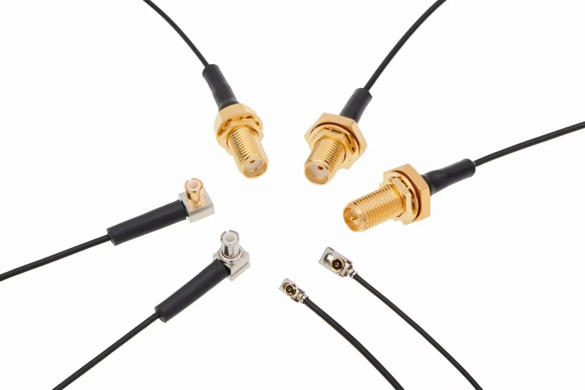
In many RF projects, the connector selection is not the difficult part. The difficult part is making the connection work in the actual product structure.
A direct adapter is useful when two connectors are already close together.
For example:
- SMA port to BNC test instrument
- N-type port to SMA equipment
- Short transition between two RF interfaces
The connection is simple and compact.
However, the situation changes when the two ports are separated by distance or located at different angles.
A rigid adapter can create several problems:
- excessive mechanical force on the connector;
- limited installation direction;
- difficulty routing inside the enclosure;
- additional stress during repeated connection.
An adapter cable solves these issues by adding a flexible coaxial section between the two interfaces.
A typical RF adapter cable contains:
- Connector A
- Connector B
- Coaxial cable
- Termination structure
- Strain relief section
Each part affects the final result.
A buyer may only specify “SMA adapter cable”, but the supplier still needs to know whether the application requires SMA male, SMA female, RP-SMA, cable diameter, length, and frequency range.
A connector name alone is not enough to define an RF assembly.
Where Are Adapter Cables Used in RF Systems?
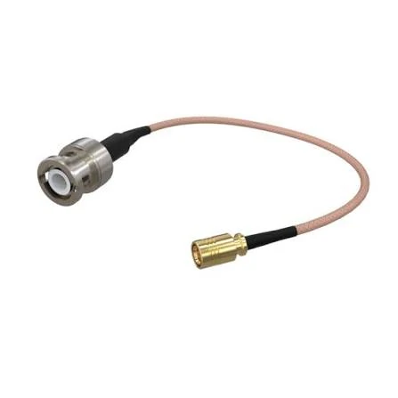
This BNC to SMA adapter cable combines two RF connector types with a flexible coaxial cable, allowing easier routing and installation in RF testing, antenna systems, and wireless equipment applications.
Adapter cables are commonly found in systems where compact RF modules need to connect with larger external interfaces.
Typical applications include:
- antenna systems;
- wireless modules;
- GPS equipment;
- Wi-Fi devices;
- IoT products;
- RF measurement setups;
- prototype development platforms.
A common example is a small antenna connector on a PCB.
Many wireless modules use miniature interfaces such as U.FL or IPEX because the PCB space is limited. During development, engineers often need to connect these modules to standard SMA antennas or test equipment.
The connection may look simple:
U.FL → coaxial cable → SMA
But the cable design still needs attention.
A very thin coaxial cable improves flexibility, but longer lengths may increase attenuation. A larger cable may reduce loss but create installation problems because of the bend radius and space requirement.
This is a typical engineering trade-off.
The “smallest cable” is not always the best choice, and the “lowest loss cable” is not always practical.
Why Are Adapter Cables Different From RF Cable Assemblies?
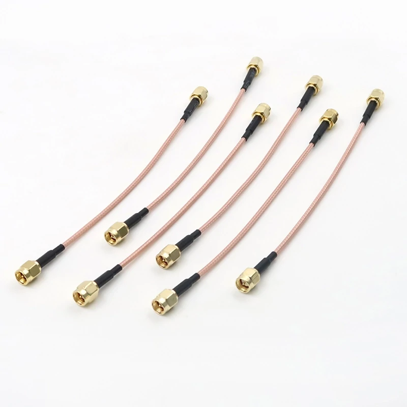
A selection of SMA adapter cables featuring different connector combinations and cable lengths, suitable for RF modules, antennas, test equipment, and custom cable assemblies.
The difference between an adapter cable and an RF cable assembly is often misunderstood.
Both products contain connectors and coaxial cable. The difference is mainly related to their purpose.
An adapter cable is usually selected when different interfaces need to be connected without changing the original equipment design.
An RF cable assembly is usually created for a defined connection point in a product or system.
| Product | Main Purpose | Common Application | Main Consideration |
| RF Adapter | Short interface conversion | Temporary connection | Connector compatibility |
| Adapter Cable | Interface conversion with flexible routing | Prototype, testing, antenna connection | Cable selection and routing |
| RF Cable Assembly | Fixed RF connection | Production equipment | Repeatability |
For purchasing teams, confusing these products can create unnecessary replacement work.
A sample may pass because the cable is short and installation conditions are ideal. After mass production, cable routing, bending, and assembly variation can change the RF result.
This is why experienced buyers normally provide more information than just connector names.
A better specification looks like:
SMA female to BNC male adapter cable, RG316 cable, 300 mm length, 50Ω impedance, DC–6 GHz.
Compared with:
SMA adapter cable
The second description leaves too many variables open.
What Information Should Buyers Confirm Before Ordering?
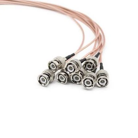
BNC adapter cable assemblies provide reliable RF signal connections for laboratory testing, communication devices, and antenna systems with flexible cable routing.
Before requesting an adapter cable quotation, the following items should be defined:
| Specification | Example |
| Connector A | SMA Male |
| Connector B | BNC Female |
| Cable Type | RG316 |
| Length | 300 mm |
| Impedance | 50Ω |
| Frequency | DC–6 GHz |
| Application | Test equipment / Antenna |
| Quantity | Sample or production batch |
These details help avoid a common sourcing issue: receiving a cable that physically connects but does not match the RF requirement.
For low-frequency connections, small differences may not be obvious.
At higher frequencies, connector geometry, cable construction, and termination quality become much more sensitive.
A continuity test can confirm the electrical path is connected. It cannot confirm whether the assembly will maintain the expected RF characteristics.
Match Connector Interfaces Before Selecting the Cable
The connector combination should be confirmed before deciding the cable type.
Common adapter cable combinations include:
- SMA to BNC
- SMA to N Type
- BNC to SMA
- U.FL to SMA
- N Type to SMA
The connector gender also needs confirmation.
For SMA connectors, buyers should check:
- male or female interface;
- standard SMA or RP-SMA;
- thread structure;
- center contact type.
Two connectors may look almost identical in pictures but are not interchangeable.
This is especially common in wireless products using SMA and RP-SMA interfaces.
How Should You Match Adapter Cable Interfaces Correctly?
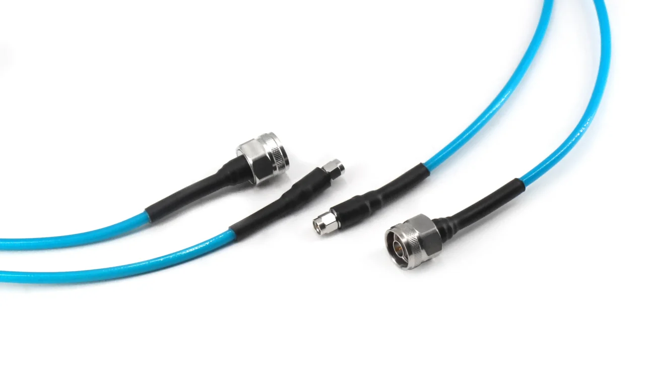
A cable can be manufactured perfectly and still fail the application if the connector interfaces are not matched correctly.
This is a common issue during RF sourcing. The drawing may show the correct connector family, but several details are missing:
- connector gender;
- polarity;
- impedance;
- mounting method;
- cable termination style.
For low-frequency applications, some mistakes may only create installation problems. At higher frequencies, the same mistake can affect VSWR, insertion loss, and measurement accuracy.
Before selecting an adapter cable, the first step is to define both ends of the connection.
A complete description should include:
Connector A + Connector B + Cable Type + Length + Frequency Requirement
For example:
SMA female to BNC male adapter cable, RG316 coaxial cable, 500 mm, 50Ω, DC–6 GHz.
This description gives the supplier enough information to evaluate the complete RF path.
A request such as:
“Need SMA cable adapter”
is still incomplete because SMA describes only one interface. It does not define what the other side should connect to or what cable structure is required.
Select connector combinations according to equipment ports
Different RF systems use different connector families.
This avoids unnecessary changes after the sample arrives.
Confirm connector gender and polarity before ordering
Connector appearance can be misleading.
SMA and RP-SMA are a good example.
Both connectors have the same external thread size and similar dimensions. However, their center contact arrangement is different.
A standard SMA connector normally has:
- male connector with center pin;
- female connector with socket contact.
RP-SMA reverses this structure.
This means a standard SMA cable may not correctly connect to an RP-SMA antenna system.
The same issue appears with other RF interfaces where similar-looking products are available with different mechanical configurations.
For adapter cable purchasing, the following information should be clearly specified:
| Item | Example |
| Connector Type | SMA |
| Gender | Male / Female |
| Polarity | Standard SMA / RP-SMA |
| Mounting Style | Cable mount / Panel mount |
| Interface Standard | Manufacturer specification if required |
A supplier can manufacture according to a part number, drawing, or photo. But relying only on appearance creates unnecessary risk.
How Does Cable Type Affect Adapter Cable Selection?
The connector determines how the cable connects. The cable determines how the RF signal travels.
Many buyers focus on the connector name and ignore the coaxial cable inside. This can become a problem when the operating frequency increases or the cable length changes.
An adapter cable using RG316 and another using low-loss coax may have identical connectors but different RF behavior.
The selection depends on several factors:
- operating frequency;
- cable length;
- available installation space;
- required flexibility;
- acceptable attenuation.
Choose flexible coax cables for compact installations
Flexible coaxial cables are widely used in adapter cables because they simplify installation.
Common examples include:
- RG316;
- RG174;
- thin RF coax cables such as 0.81 mm or 1.13 mm cables.
These cables are useful for:
- internal equipment connections;
- GPS modules;
- Wi-Fi devices;
- IoT products;
- short antenna jumpers.
Their advantage is not only size.
A flexible cable reduces mechanical stress on the connector during assembly.
For example, a small PCB connector connected directly to a rigid adapter may experience force when the enclosure is closed. A flexible cable section allows the connection angle to adjust.
However, flexibility usually comes with a trade-off.
Smaller cables normally have higher attenuation compared with larger low-loss cables.
Select low-loss cable when distance increases
As cable length increases, attenuation becomes a more important factor.
The loss of an adapter cable is affected by:
- cable material;
- dielectric structure;
- conductor size;
- shielding design;
- operating frequency.
A short RG316 cable may work well inside a device.
A several-meter antenna cable may require a larger low-loss coaxial cable.
The mistake is choosing the cable only based on diameter.
A thinner cable may be easier to install, but if the signal travels a longer distance, the additional loss may exceed the mechanical advantage.
A simple selection comparison:
| Cable Type | Advantage | Typical Application |
| RG316 | Small diameter, flexible | GPS, Wi-Fi, RF modules |
| RG174 | Cost-effective, compact | Short RF connections |
| RG58 | Larger conductor size | General RF testing |
| Low-loss coax | Lower attenuation | Longer antenna paths |
| Semi-rigid cable | Stable RF characteristics | Microwave systems |
Balance cable diameter with installation space
The largest cable is not always the best solution.
In compact equipment, cable routing is often limited by:
- enclosure height;
- bending space;
- connector location;
- nearby components.
A cable that performs well electrically may create assembly problems if the bend radius is too large.
This is especially important for production products.
A prototype may be assembled by hand with extra space. A production line may require hundreds or thousands of units where every cable must follow the same routing path.
Before approving an adapter cable, buyers should check:
- minimum bend radius;
- cable outer diameter;
- strain relief structure;
- connector fixing method.
A small mechanical change can affect long-term reliability.
How Can You Estimate Adapter Cable Signal Loss?
Loss estimation is often ignored during early sourcing.
The first prototype may work because the cable is short. Later, the production version may use a longer cable or additional adapters.
The RF path changes.
A practical calculation method is:
Total Loss (dB) = Cable Length × Cable Attenuation + Connector Loss + Adapter Transition Loss
For an adapter cable, the loss is not only from the coaxial cable.
Additional factors include:
- connector transition;
- solder or crimp quality;
- number of mating interfaces;
- cable bending;
- assembly variation.
A useful purchasing habit is to calculate the expected loss before finalizing the cable specification.
If the system operates close to the frequency limit, leave additional margin instead of selecting a cable only based on minimum requirements.
How Do SMA Adapter Cables Support RF Module Applications?
SMA adapter cable is often selected at the development stage because it gives engineers more freedom when connecting RF modules, antennas, and test equipment.
However, the first sample is rarely the final answer.
During prototype testing, a short cable placed on the workbench may show acceptable results. After the same design moves into an enclosure, the cable routing changes, the bend angle increases, and the distance between the module and antenna becomes fixed.
The RF result may change.
This is why engineers usually evaluate the whole connection rather than only checking whether the SMA connector can be installed.
An SMA adapter cable includes several factors:
- SMA interface structure;
- opposite connector type;
- coaxial cable selection;
- cable length;
- termination process;
- installation direction.
The connector is only the visible part. The cable section often determines whether the assembly fits the actual application.
Connect compact RF modules with external antennas
Small RF modules usually have limited PCB space, so miniature connectors are commonly used.
Examples include:
- U.FL;
- IPEX;
- MMCX;
- other miniature RF interfaces.
These connectors are suitable for internal connections but are not always convenient for testing or external antenna installation.
During development, engineers often need a transition cable:
Miniature RF connector → coaxial cable → SMA interface
After conversion to SMA, the module can connect with:
- standard antennas;
- RF test equipment;
- external evaluation boards;
- laboratory cables.
A typical example is a GPS module.
The production design may use a small embedded antenna, but during development engineers may need to compare several antenna options. An adapter cable allows quick replacement without changing the PCB design.
The cable length needs attention here.
For a low-frequency GPS application, a longer flexible cable may be acceptable. For a higher-frequency wireless application, the same length may create unnecessary signal attenuation.
The correct choice depends on the actual RF path.
Choose SMA cable direction according to equipment layout
Connector direction is often decided too late.
A customer may first confirm the electrical specification and only discover during assembly that the connector cannot fit into the enclosure.
Common SMA adapter cable structures include:
- straight SMA;
- right-angle SMA;
- custom orientation versions.
A straight connector is simple and suitable for open space.
A right-angle connector is often better when:
- the PCB edge is close to the housing wall;
- the cable needs immediate turning;
- repeated movement may stress the connector.
For example, a portable RF device may experience vibration or frequent handling. A cable exiting directly from the connector can create continuous mechanical force.
In these cases, the cable routing design matters as much as the connector specification.
How Do Adapter Cables Compare With Direct RF Cable Assemblies?
The difference between adapter cables and RF cable assemblies usually appears when a project moves from development into production.
During the prototype stage, engineers often need flexibility.
They may change:
- antenna position;
- RF module supplier;
- test equipment;
- connector interface.
An adapter cable is useful because it allows these changes without redesigning the entire system.
Production equipment has different requirements.
A production line normally prefers a fixed RF cable assembly because the connection needs to remain consistent from unit to unit.
| Application Situation | More Suitable Option | Reason |
| Prototype testing | Adapter cable | Interface changes are common |
| Engineering verification | Adapter cable | Easy replacement |
| Laboratory measurement | Adapter cable | Supports different instruments |
| Final equipment assembly | RF cable assembly | Fixed specification |
| Large quantity production | RF cable assembly | Easier process control |
The difference is not simply about performance.
It is about controlling variables.
Every additional connector transition introduces another point that needs to be controlled.
For a laboratory setup, that flexibility is valuable.
For a production product, too many connection points may increase assembly variation.
Use an adapter cable when flexibility is still required
A simple way to judge the application:
The connection changes frequently → adapter cable is usually practical.
The connection becomes part of the final product → fixed cable assembly is usually easier to manage.
This is why many RF engineers use adapter cables during development but replace them with dedicated cable assemblies after the design is finalized.
The decision often happens after testing.
A prototype may require several cable combinations:
- SMA to BNC for measurement;
- SMA to SMA for antenna comparison;
- U.FL to SMA for module evaluation.
After the product enters mass production, the final connection normally becomes fixed.
How Should Adapter Cables Be Tested Before Shipment?
A cable assembly can look correct and still have hidden problems.
Visual inspection can confirm:
- connector appearance;
- cable damage;
- assembly condition.
It cannot confirm:
- impedance matching;
- insertion loss;
- VSWR behavior.
For this reason, inspection requirements should match the application.
A short cable used for a basic connection may only require continuity testing.
A test cable used near the upper frequency range may require additional RF measurement.
Common inspection items:
| Test Item | What It Checks |
| Appearance inspection | Connector and cable condition |
| Continuity test | Electrical connection |
| VSWR test | RF matching condition |
| Insertion loss test | Signal attenuation |
| Pull test | Mechanical connection strength |
One detail often missed during repeat orders is maintaining the same assembly process.
A replacement batch may use:
- different cable supplier;
- different crimp tooling;
- different termination settings.
The cable may look identical, but the internal structure can change.
For applications with strict RF requirements, keeping the original drawing, cable model, and inspection method is important.
What Should Be Included in an Adapter Cable Purchase Request?
Many quotation delays happen because the RF requirement is incomplete.
A supplier can quote a connector. It is much harder to quote a complete adapter cable without knowing the application.
A practical RFQ should include:
| Required Information | Example |
| Connector A | SMA Female |
| Connector B | BNC Male |
| Cable Type | RG316 |
| Length | 500 mm |
| Impedance | 50Ω |
| Frequency Range | DC–6 GHz |
| Application | Antenna / Test |
| Quantity | Sample or Production |
| Test Requirement | VSWR / Insertion Loss |
For custom adapter cables, drawings or photos are usually more useful than a product name.
Important details include:
- connector orientation;
- cable exit direction;
- mounting position;
- required tolerance.
A short note such as “same as existing cable” is only useful if the original part number or drawing is available.
FAQ
Can an adapter cable use different connector families?
Yes, but the connector transition is only one part of the selection. The impedance, frequency range, cable type, and application also need to match.
Does a longer adapter cable always create problems?
Not always. The impact depends on frequency, cable type, and acceptable system loss. A short low-loss cable and a long flexible cable may have very different results.
Why can two SMA adapter cables with the same connectors perform differently?
The internal cable, termination method, connector quality, and assembly process can all affect RF performance.
When should an adapter cable be replaced by an RF cable assembly?
When the product design becomes fixed and production repeatability becomes more important than connection flexibility.
