
A test setup can fail even when every connector appears to fit correctly.
A common RF sourcing mistake happens when an engineer replaces a missing interface with a physically compatible adapter but ignores impedance, frequency range, or connector gender. The assembly connects mechanically, the signal appears on the screen, and the problem is discovered later during a higher-frequency measurement or production test.
An RF adapter is often treated as a simple mechanical conversion part, but in an RF path it becomes part of the transmission line. The adapter introduces another interface, another contact point, and another possible source of mismatch. For low-frequency connections, the impact may be small. For microwave testing, antenna systems, and precision measurement setups, the details become much harder to ignore.
This guide explains how RF adapters are selected, how interfaces should be matched, and what information engineers and buyers should confirm before ordering.
How Do RF Adapters Create Reliable Interface Transitions?
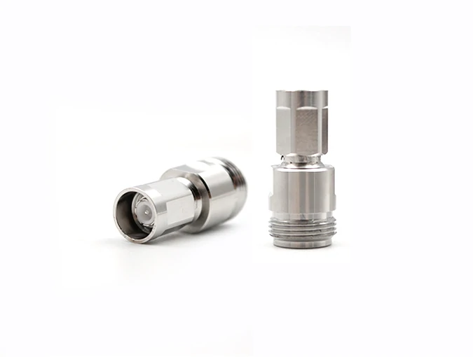
An RF adapter creates a controlled connection between different RF connector standards, helping engineers connect test equipment, antenna systems, and RF modules while maintaining proper impedance and frequency compatibility.
RF systems rarely use only one connector standard across every device. A laboratory may have a VNA with one interface, a cable assembly with another, and a device under test using a third connector family.
Replacing all interfaces is usually unrealistic. The more practical solution is an RF adapter that provides a controlled transition between different connector standards.
Typical applications include:
- RF modules
- antenna systems
- communication equipment
- test instruments
- prototype hardware
- microwave measurement setups
An RF adapter allows existing equipment to work together without redesigning the complete RF path.
However, not every connector conversion is automatically suitable.
A SMA-to-N adapter, for example, is not defined only by “SMA on one side and N on the other side.” A complete specification also includes:
- male or female interface
- 50Ω or 75Ω impedance
- operating frequency range
- connector plating
- mechanical structure
- environmental requirements
A missing detail in the purchase specification can easily result in an adapter that looks correct but cannot be used reliably.
How Is an RF Adapter Different From a Connector or Cable Assembly?
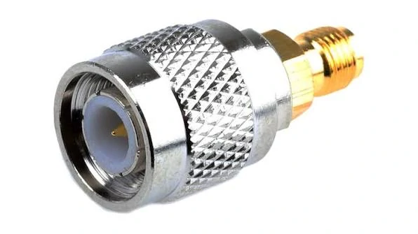
RF adapters convert connector interfaces, while connectors and cable assemblies provide fixed connections or complete RF transmission paths for different applications.
Many purchasing errors happen because RF adapters, connectors, and cable assemblies are considered interchangeable.
They solve different problems.
| Product | Main Function | Typical Use |
| RF Connector | Provides a fixed interface | Cable termination or equipment port |
| RF Adapter | Converts one interface to another | SMA to BNC, N to SMA conversion |
| Adapter Cable | Provides conversion with flexibility | Tight installation areas or vibration environments |
| Cable Assembly | Provides a complete RF connection path | Production equipment and fixed systems |
An RF connector normally stays within the same interface family. An adapter exists because two different interfaces need to communicate.
For example, a test engineer may have a BNC output from a signal generator but need to connect it to an SMA input on an RF module.
The same principle applies to antenna development. An engineer may need an antenna adapter during prototype testing because the final enclosure interface has not yet been finalized.
When Should You Use an RF Adapter Instead of Changing the Equipment Interface?
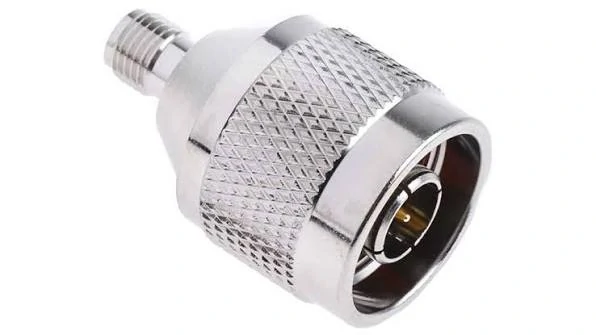
A SMA to N type RF adapter provides interface conversion between compact RF modules and larger antenna systems while maintaining electrical compatibility.
Changing an equipment interface sounds simple but often creates unnecessary cost.
A modification may require:
- redesigning a PCB layout
- changing an enclosure opening
- updating mechanical drawings
- repeating qualification tests
- rebuilding cable assemblies
An RF adapter is usually the practical choice when the requirement is temporary or when existing equipment cannot be modified.
How Should You Match RF Adapter Interfaces Before Ordering?
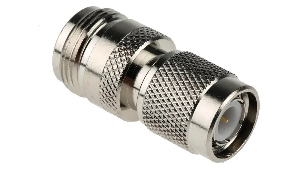
RF adapter selection requires checking connector type, impedance, frequency rating, and application requirements to achieve stable RF performance.
A correct RF adapter selection starts from both ends of the RF path.
Do not describe the requirement only as:
“Need an RF adapter.”
That description is incomplete for manufacturing.
A supplier needs to know:
- Interface A
- Interface B
- Gender
- Impedance
- Frequency range
- Application
- Quantity
- Test requirements
Confirm Connector Families on Both Sides of the Conversion
Common RF adapter interfaces include:
- SMA
- BNC
- N Type
- TNC
- UHF
- F Type
Each connector family has different mechanical characteristics and typical application areas.
The interface alone does not determine compatibility.
A SMA male adapter cannot replace a SMA female adapter simply because both belong to the same connector family.
Match Male and Female Interfaces Correctly
Connector gender is one of the easiest specifications to overlook.
Before ordering, confirm:
- plug or jack
- male or female
- center pin or socket structure
- thread compatibility
The adapter must match both mechanical connection points.
A common production issue occurs when an adapter is selected based only on the product name. For example, “SMA adapter” may refer to many different versions:
- SMA male to SMA male
- SMA female to SMA female
- SMA male to BNC female
- SMA female to N male
The interface direction matters.
RF Adapter Interface Matching Table
| Conversion | Typical Application | Main Check |
| SMA ↔ BNC | RF module and test equipment | Gender + impedance |
| SMA ↔ N Type | Antenna and RF systems | Frequency + cable compatibility |
| BNC ↔ TNC | Rugged RF conversion | Thread compatibility |
| Coax ↔ SMA | Compact RF devices | Cable diameter |
| Coax ↔ N Type | Outdoor RF systems | Mechanical strength |
| UHF ↔ SMA | Radio antenna systems | Frequency limitation |
This table can be used as a first screening step before requesting samples or production quantities.
A correct adapter selection starts with the complete RF path, not the connector name printed on the purchase order.
How Does Impedance Affect RF Adapter Selection?
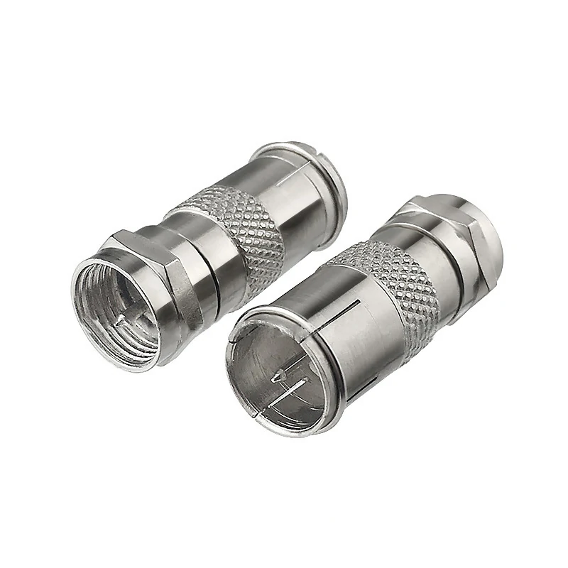
Custom RF adapter solutions support specific interface combinations, mechanical dimensions, and RF performance requirements for testing and communication systems.
A connector can physically mate and still create an RF problem.
This is one of the most common mistakes when selecting an RF adapter. Engineers sometimes focus on mechanical compatibility first, then discover unexpected insertion loss, unstable measurements, or poor return loss after the system operates at higher frequencies.
The adapter must match the electrical characteristics of the RF path, especially impedance.
Most RF communication and measurement systems use 50 ohm impedance, while some broadcast and video systems use 75 ohm impedance. These two systems may use similar-looking coaxial interfaces, but they are not interchangeable.
Why Are 50Ω RF Adapters Common in Communication and Test Systems?
A 50 ohm adapter is widely used in:
- wireless communication equipment
- antenna systems
- RF modules
- VNA testing
- microwave measurement systems
The 50Ω standard is mainly associated with minimizing transmission loss while maintaining practical power handling capability.
For example, an SMA-to-N adapter used between a test cable and antenna feed should normally maintain:
- 50Ω impedance
- compatible frequency range
- correct connector gender
- suitable mechanical structure
If a 50Ω system is connected through an incorrect impedance adapter, the signal reflection increases. The connection may still pass a basic continuity check, but RF measurement results can shift.
Why Should You Avoid Selecting RF Adapters Only by Physical Fit?
A connector that screws together correctly can still introduce problems.
Before selecting an adapter, verify:
- impedance
- frequency range
- signal type
- cable characteristics
- application environment
A typical example is using an adapter stack during RF testing.
A single adapter may introduce minimal loss.
Each transition adds another interface. At microwave frequencies, these small effects can accumulate.
RF Adapter Impedance Decision Tree
| Decision Field | Check |
| Application | RF / Video / Broadband |
| Impedance | 50Ω / 75Ω |
| Connector | SMA / BNC / N / TNC |
| Gender | Male / Female |
| Frequency | MHz / GHz |
| Environment | Indoor / Outdoor |
This decision process helps avoid a common procurement issue: ordering an adapter that matches the connector name but not the RF system.
When Should You Select SMA Adapters for Compact RF Modules?
However, SMA selection still requires checking:
- standard SMA or reverse polarity SMA
- male/female interface
- cable compatibility
- operating frequency
For example, an SMA adapter used in a 6 GHz wireless application may be completely different from a precision microwave SMA adapter used near 18 GHz.
The connector appearance alone does not define the RF capability.
Why Are BNC Adapters Popular in Laboratory Equipment?
BNC adapters are widely used in test environments because of their quick locking mechanism.
Typical applications:
- oscilloscopes
- signal generators
- measurement equipment
- laboratory instruments
The advantage of BNC is not only convenience. In a laboratory environment, engineers frequently connect and disconnect equipment during evaluation.
A BNC-to-SMA adapter can help connect standard measurement equipment with compact RF modules.
When Are N Type Adapters Better for Antenna and Outdoor Systems?
Typical applications:
- base stations
- outdoor antenna systems
- wireless communication links
- RF infrastructure
Compared with smaller connectors, N Type interfaces provide:
- larger mechanical structure
- better environmental tolerance
- higher power capability in many applications
For outdoor systems, the adapter selection should also consider:
- sealing method
- corrosion resistance
- mounting condition
- cable diameter
- weather exposure
An antenna adapter installed outdoors experiences conditions that a laboratory adapter never sees.
Temperature changes, vibration, moisture, and repeated cable movement can affect long-term reliability.
Should TNC and UHF Adapters Be Considered for Special Applications?
Some applications require connector families outside the common SMA, BNC, and N Type range.
TNC adapters are often selected when threaded coupling is preferred in environments with vibration.
Applications include:
- mobile communication systems
- industrial RF equipment
- vehicle-mounted systems
UHF adapters are still used in some radio applications, although they are generally limited compared with modern microwave connector families.
When selecting UHF adapters, frequency limitations should be reviewed carefully.
A connector suitable for traditional radio equipment may not be suitable for high-frequency RF testing.
RF Adapter Selection by Application
| Connector Family | Common Application | Main Selection Concern |
| SMA | RF modules, GPS, Wi-Fi, test boards | Frequency + polarity |
| BNC | Laboratory instruments | 50Ω / 75Ω identification |
| N Type | Antenna and outdoor RF | Mechanical strength |
| TNC | Mobile and vibration environments | Thread compatibility |
| UHF | Radio systems | Frequency limitation |
A practical rule for buyers is simple: choose the adapter according to the complete RF path, not only the connector interface.
A SMA adapter connected to the wrong cable, wrong impedance, or wrong frequency range can become the weakest point in the system.
How Do RF Adapters Compare With Adapter Cables and Complete RF Assemblies?
A rigid adapter solves one problem quickly: two connectors do not match.
That is usually enough for a bench test.
The situation changes when the connection becomes part of an actual product, a test fixture used every day, or equipment installed in the field. The same adapter that works perfectly on a laboratory table may create problems when the cable is pulled sideways, the enclosure space becomes limited, or the connection needs hundreds of mating cycles.
This is where engineers usually need to decide between an RF adapter, an adapter cable, and a complete RF cable assembly.
The difference is not only the product shape. It is about how the RF path will be used.
When Does a Simple RF Adapter Make More Sense Than a Cable?
An RF adapter is usually the first choice when the conversion requirement is temporary or the installation space is simple.
Typical examples:
- connecting different test instruments;
- converting an existing equipment port;
- checking a prototype board;
- matching laboratory cables during development.
A test engineer may have several cables already available. Instead of replacing all cables, adding a SMA-to-BNC or N-to-SMA adapter can solve the connection problem immediately.
For laboratory work, this flexibility is valuable.
However, the limitation is also obvious.
The adapter creates an additional connection point.
Each additional interface introduces another mechanical contact and another possible mismatch location.
At low frequencies, the effect may be difficult to notice. At microwave frequencies, small differences in contact condition, machining tolerance, and alignment can become measurable.
Why Are Adapter Cables Often Used Instead of Multiple RF Adapters?
There are situations where a rigid adapter is not the best mechanical solution.
A good example is a PCB-mounted RF connector.
The connector on a board may be electrically capable of handling the signal, but the mechanical force from a heavy cable or adapter can damage the solder joint over time.
An adapter cable changes the situation.
Instead of forcing the equipment port to support the weight of the connection, the flexible cable section absorbs movement.
Common reasons to select an adapter cable include:
- limited installation space;
- vibration conditions;
- frequent equipment movement;
- reducing stress on PCB connectors;
- avoiding a long adapter stack.
For example, a short SMA female to N male cable assembly can be easier to install than combining an SMA adapter with a separate N cable.
The RF path becomes longer, but the mechanical reliability may improve.
This is a trade-off engineers often need to consider.
The shortest connection is not always the most reliable connection.
When Should a Complete RF Cable Assembly Replace an Adapter Combination?
For production equipment, a complete cable assembly is often the cleaner solution.
A production line usually values:
- repeatability;
- consistent electrical performance;
- easier incoming inspection;
- fewer loose parts.
A cable assembly can define:
- exact cable type;
- exact cable length;
- connector combination;
- termination method;
- labeling requirements.
This reduces variation between units.
A common sourcing mistake is building a production cable from several standard adapters because the first sample worked.
The sample may pass because:
- the cable was short;
- the connectors were new;
- the installation was careful.
After mass production, the same structure may experience:
- inconsistent tightening;
- connector damage;
- cable routing differences;
- unstable test results.
For production applications, reducing unnecessary interfaces is usually worth considering.
RF Adapter vs Adapter Cable vs Cable Assembly Decision Table
| Project Condition | Recommended Option | Main Reason |
| Temporary laboratory test | RF Adapter | Fast interface conversion |
| Prototype evaluation | RF Adapter / Adapter Cable | Flexible during design changes |
| Tight enclosure installation | Adapter Cable | Easier routing |
| Vibration environment | Adapter Cable | Reduces mechanical stress |
| Long-term equipment installation | Cable Assembly | Better repeatability |
| High-volume production | Cable Assembly | Simplifies BOM and inspection |
This table is not a rule that applies to every project.
A high-frequency calibration setup may still require specialized adapters even in a permanent system. The correct choice depends on the RF requirement and mechanical environment together.
How Should Frequency Rating Influence RF Adapter Selection?
The connector label is not enough.
Two adapters may both be called “SMA adapters,” but their actual RF capability can be different.
The difference comes from internal construction:
- contact design;
- dielectric material;
- machining accuracy;
- interface alignment;
- manufacturing tolerance.
At higher frequencies, these details become more important.
Why Should Buyers Leave Frequency Margin Instead of Selecting the Minimum Rating?
Selecting an adapter exactly at the operating frequency is risky.
A system working at 6 GHz does not always need a 6 GHz-rated adapter.
Real installations are affected by:
- cable bending;
- temperature variation;
- connector wear;
- repeated assembly;
- manufacturing differences.
A small frequency margin provides additional tolerance.
A practical reference:
| Frequency Margin | Application Consideration |
| Close to operating frequency | Suitable only after verification |
| 1.2× operating frequency | Common engineering choice |
| 1.5× or higher | Better for test and measurement |
| 2× margin | Preferred for sensitive RF paths |
The adapter rating is only one part of the system.
A 26.5 GHz adapter connected with an unsuitable cable can still produce poor results.
The cable assembly may become the limiting factor before the adapter does.
What Should Be Checked Before Using RF Adapters in VNA and Microwave Testing?
VNA applications require more attention than normal equipment connections.
A VNA does not only check whether a signal passes through. It measures RF behavior.
Important parameters include:
- VSWR;
- insertion loss;
- return loss;
- calibration repeatability.
Adapter condition matters.
A frequently used test adapter may develop:
- worn contact surfaces;
- damaged threads;
- poor mechanical repeatability.
This is why many laboratories manage adapter usage carefully and replace critical adapters before measurement uncertainty becomes unacceptable.
How Should RF Adapters Be Inspected Before Installation?
Many RF connection problems are not caused by the wrong model.
They come from handling.
Before installation, inspect:
- connector threads;
- center contact;
- plating condition;
- contamination;
- mechanical damage.
A small particle inside the interface can affect contact pressure.
A damaged thread can create uneven mating force.
These problems are easy to overlook because the connector may still tighten normally.
Why Is Continuity Testing Not Enough for RF Adapter Verification?
Continuity testing answers one question:
“Is there an electrical connection?”
RF testing answers a different question:
“Does the signal travel through this connection correctly?”
An adapter can pass continuity but still have:
- impedance discontinuity;
- excessive reflection;
- higher insertion loss.
For basic applications, continuity inspection may be sufficient.
For higher-frequency systems, engineers may require:
- VSWR measurement;
- insertion loss testing;
- VNA verification.
The inspection method should match the application risk.
RF Adapter Incoming Inspection Checklist
| Inspection Item | Check Requirement |
| Model Number | Match purchase specification |
| Interface Side A | Correct connector type |
| Interface Side B | Correct connector type |
| Gender | Male/Female confirmed |
| Impedance | 50Ω or 75Ω verified |
| Frequency Rating | Above application requirement |
| Mechanical Fit | Thread and locking checked |
| Contact Surface | Clean and undamaged |
| RF Test | Required for critical applications |
| Packaging Label | Traceable information available |
This checklist can help buyers reduce wrong-part receiving issues before the adapter enters production.
What Information Should Be Included When Ordering a Custom RF Adapter?
Many supplier misunderstandings start with incomplete descriptions.
“Need SMA adapter” does not define a product.
A complete RF adapter request should include the entire transition requirement.
A useful RF specification normally includes:
- connector A;
- connector B;
- gender;
- impedance;
- frequency;
- application;
- quantity;
- drawing or reference photo.
For custom adapters, additional information may be needed:
- mechanical dimensions;
- panel mounting requirement;
- material requirement;
- plating specification;
- inspection standard.
RF Adapter RFQ Template
| RFQ Item | Example |
| Interface A | SMA Female |
| Interface B | N Male |
| Impedance | 50Ω |
| Frequency | DC–6 GHz |
| Application | Antenna Test |
| Environment | Indoor / Outdoor |
| Quantity | Prototype / Production |
| Drawing | Required if customized |
| Test Requirement | VSWR / Insertion Loss if needed |
A clear RFQ reduces back-and-forth communication and helps suppliers recommend the correct structure instead of simply matching the connector name.
FAQ
Can any two RF connectors be connected with an adapter?
No. The connector interface, gender, impedance, frequency range, and application must all be considered. A mechanical connection does not guarantee correct RF performance.
Does adding more RF adapters reduce signal quality?
It can. Each adapter adds another interface into the transmission path. In high-frequency systems, unnecessary adapter stacking should be avoided.
Is an adapter cable always better than an RF adapter?
Not always. An adapter is usually better for quick conversion. An adapter cable is more suitable when flexibility and mechanical protection are required.
How do I choose the right RF adapter for my application?
Choosing an RF adapter requires more than checking whether two connectors can physically connect. You should confirm the connector type on both sides, male or female interface, impedance, operating frequency, and the actual application environment.
For example, an adapter used for VNA testing may require different performance specifications compared with an adapter used for a general communication system. Matching the complete RF path helps avoid signal reflection, connection issues, and measurement errors.