
A wireless device can fail before the antenna itself becomes the problem.
A common example happens during hardware integration: the antenna fits mechanically, the connector threads correctly, and the first prototype passes a bench test. After moving into production, engineers discover unstable signal levels, unexpected VSWR changes, or poor RF performance near the operating frequency.
The reason is often a small interface decision.
An antenna adapter may look like a simple mechanical converter, but it becomes part of the RF path. Connector type, impedance, frequency capability, and mating structure all affect whether the connection works as expected.
For GPS modules, WiFi devices, IoT terminals, wireless gateways, and RF test systems, selecting an antenna adapter requires more than matching two connector shapes.
How Do Antenna Adapters Connect Different RF Systems?
In many wireless designs, the antenna interface does not directly match the RF module interface.
A device may use a miniature connector internally while the external antenna uses a larger threaded connector. A test setup may require converting from one connector family to another. Outdoor communication equipment may need a different interface compared with an indoor embedded module.
This is where an antenna adapter is used.
The adapter provides a controlled transition between two RF interfaces while keeping the connection path mechanically compatible.
The adapter is not the same as a cable and not the same as a connector.
The connector defines the physical interface. The cable carries the RF signal over a certain distance. The adapter creates a transition between two connector standards.
That difference matters during sourcing.
A physically compatible adapter can still be electrically unsuitable.
For example, an adapter that connects correctly between two interfaces may introduce additional mismatch if the impedance or frequency rating does not match the RF system.
Where Are Antenna Adapters Used Between Antennas and RF Hardware?
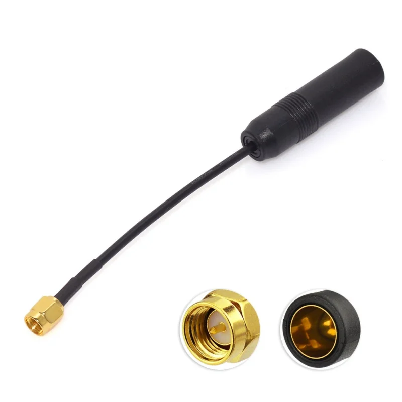
Antenna adapters appear in many wireless systems because connector standards vary between applications.
GPS equipment is a typical example.An external antenna adapter allows quick replacement between antennas with different connector styles.
RF laboratories also rely on adapters.
A signal generator, spectrum analyzer, or VNA may use a standard test connector, while the device under test uses another interface. The adapter creates a temporary measurement connection.
However, every additional interface should be considered carefully.
Each connector transition adds another mechanical connection point. At lower frequencies, the impact may be small. At higher frequencies, small geometry differences can affect insertion loss and VSWR.
The adapter should solve an interface problem, not hide an interface design problem.
If a product is still in development, engineers should decide whether an adapter is the right long-term solution or whether a custom cable assembly would create a cleaner RF path.
How Do You Match Antenna Adapter Interfaces Correctly?
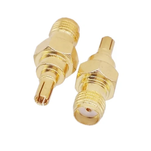
N type RF tee adapter is used in antenna systems, wireless communication equipment, and RF test setups. The 50 ohm impedance design helps maintain signal matching across connected components.
The first mistake during antenna adapter selection is choosing only by appearance.
Two connectors may look similar but use different standards.
SMA and RP-SMA are a common example. The external thread size may appear identical, but the center contact arrangement is different. They are not interchangeable without confirming the actual interface specification.
The same issue appears with miniature RF connectors.
A connector used for a compact wireless module may have strict mechanical requirements. Small differences in height, locking structure, or mating force can create installation problems.
Before ordering an antenna adapter, confirm these points:
| Check Item | Why It Matters |
| Connector Type | Determines whether the adapter physically mates |
| Gender | Male/female mismatch prevents connection |
| Polarity | SMA and RP-SMA cannot be assumed interchangeable |
| Impedance | RF systems usually require matching impedance |
| Frequency Range | Adapter rating must cover the operating band |
| Installation Environment | Outdoor systems may require additional protection |
A practical procurement example:
Instead of writing:
“SMA antenna adapter”
a clearer specification would be:
“SMA male to N female adapter, 50Ω, DC–6 GHz, for outdoor antenna connection.”
The second description gives the supplier enough information to check the actual RF requirement.
For custom projects, additional details may be needed:
- equipment model
- antenna model
- cable type
- installation location
- required frequency band
- expected quantity
These details reduce the risk of receiving a mechanically correct but electrically unsuitable adapter.
How Does Impedance Affect Antenna Adapter Selection?
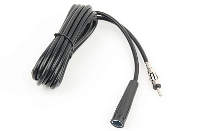
Bulkhead RF antenna adapter is designed for panel mounting applications where a stable connection between internal RF circuits and external antennas is required.
The adapter arrived, the connector fits, and the equipment powers on.
This is the stage where some RF problems stay hidden.
A connection that looks correct from the outside does not prove that the RF path is correct. For antenna systems, impedance is one of the first specifications that should be checked before placing an order.
Most wireless communication equipment uses a 50Ω RF system.
This includes:
- GPS receivers
- WiFi modules
- cellular communication equipment
- IoT gateways
- RF measurement equipment
- antenna assemblies
The antenna adapter must maintain the same impedance environment between connected components.
The adapter is only one part of the system.
A common purchasing mistake is focusing on the connector name and ignoring the complete RF path. A supplier may receive a request such as “SMA antenna adapter,” but SMA only describes the interface family. It does not define whether the adapter is suitable for the application.
Before selecting an adapter, the specification should include:
- impedance
- connector interface
- connector gender
- operating frequency
- installation environment
For example, an SMA male to N female adapter used for an outdoor antenna system should not only confirm that both connectors mate correctly. The buyer should also confirm that the adapter is 50Ω, rated for the operating band, and mechanically suitable for the installation condition.
Why Can a Correct Connector Still Create RF Loss?
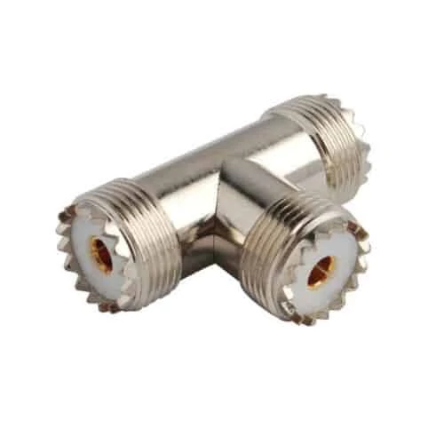
SMA antenna adapter cable is widely used in GPS modules, WiFi devices, IoT terminals, and RF testing equipment for flexible antenna integration.
A connector transition introduces another interface into the RF path.
At lower frequencies, a small mismatch may have little visible impact. At higher frequencies, connector geometry becomes more sensitive.
For laboratory measurement systems, this difference becomes easier to notice because the equipment itself has higher sensitivity.
For example, a VNA test setup may show acceptable results with one adapter but increased reflection after replacing it with a lower-grade version.
The issue is not always the connector standard.
Sometimes the transition quality is the limiting factor.
How Do 50Ω and 75Ω Antenna Adapters Differ in Real Applications?
Not every coaxial system uses the same impedance.
The two systems may use similar-looking connectors, especially BNC versions, but they are not interchangeable by default.
| Application | Typical Impedance | Common Interface | Main Concern |
| RF communication | 50Ω | SMA, N, BNC | Maintain RF matching |
| GPS / wireless modules | 50Ω | SMA, MMCX, IPEX | Compact integration |
| RF testing | 50Ω | SMA, BNC, N | Measurement accuracy |
| Video systems | 75Ω | BNC, F connector | Broadband transmission |
| CATV equipment | 75Ω | F connector | System compatibility |
A buyer ordering an adapter for a test bench may already know the connector type but overlook the impedance.
That can lead to a situation where the adapter installs correctly but does not meet measurement expectations.
The second description leaves too many decisions to the supplier.
For prototype work, engineers often discover this difference quickly because test equipment exposes small RF changes.
For production purchasing, the problem usually appears later when multiple suppliers provide visually similar parts with different electrical characteristics.
How Do Antenna Adapters Support GPS and Wireless Device Integration?
Wireless products often change connector styles during development.
A development board may use a miniature connector because space is limited. The final enclosure may require a threaded external antenna connector for easier installation.
An antenna adapter bridges this gap.
Why Are GPS Antenna Adapters Commonly Used?
GPS and GNSS designs are especially sensitive to antenna connection quality.
The received signal level is relatively low, so unnecessary loss in the RF path should be avoided.
The adapter selection depends on the physical design.
A compact tracker may use a miniature connector close to the PCB.
An industrial positioning device installed outdoors may require a stronger panel-mounted interface.
The same GPS function can lead to completely different adapter requirements.
Important considerations include:
- connector locking method
- cable routing space
- vibration exposure
- antenna location
- mating frequency
A small connector that works well on a laboratory table may not be suitable for equipment exposed to repeated movement or vibration.
How Are WiFi Antenna Adapters Selected for Wireless Equipment?
WiFi equipment creates another common adapter requirement.
Many routers, gateways, and industrial wireless products use external antennas. The external antenna allows engineers to adjust antenna placement, but it also creates more interface combinations.
Typical conversions include:
- internal miniature connector to SMA
- internal miniature connector to RP-SMA
- panel interface conversion
- test interface conversion
The RP-SMA issue deserves special attention.
Standard SMA and RP-SMA share a similar outer appearance, which creates confusion during purchasing.
The difference is inside the interface.
A standard SMA connector and an RP-SMA connector may physically screw together, but the center contact arrangement is different.
This means a product description that only says “SMA adapter” is incomplete.
The purchasing document should specify:
- SMA or RP-SMA
- male or female
- cable mount or panel mount
- impedance
- frequency range
A wrong polarity selection may not be obvious during mechanical inspection.
The problem usually appears during RF testing.
Should You Use an Antenna Adapter or Replace the Cable Assembly?
Adapters solve one problem well: changing interfaces.
They are useful when engineers need flexibility.
How Does Frequency Range Influence Antenna Adapter Choice?
An adapter marked for 18 GHz does not automatically improve a system operating at 6 GHz.
The entire RF path still matters.
Engineers should review:
- adapter frequency rating
- cable attenuation
- connector quantity
- insertion loss
- VSWR requirement
A common mistake happens when a high-frequency adapter is combined with a cable or connector that becomes the actual limitation.
A complete evaluation may still require:
- VNA measurement
- insertion loss testing
- connector inspection
- cable assembly verification
The adapter rating is only one part of the decision.
How Should Antenna Adapters Be Installed and Verified Before Use?
A new antenna adapter usually looks simple after it arrives.
The threads match. The connectors mate. The assembly fits into the equipment.
The problem is that RF performance cannot be judged only by appearance.
During installation, several small details can affect the final result. A connector tightened at the wrong position, a damaged contact surface, or excessive cable force applied to the adapter may not create an immediate failure, but it can change the RF behavior of the connection.
This is especially common in applications where the antenna is mounted away from the main device.
Examples include:
- outdoor communication equipment
- vehicle-mounted wireless systems
- industrial monitoring devices
- remote antenna installations
The adapter is often supporting the cable weight or exposed to repeated movement.
Before installation, check the basic mechanical conditions:
| Check Point | What to Confirm |
| Connector interface | Correct standard and mating structure |
| Gender | Male/female matches the equipment |
| Thread | No damage or contamination |
| Mounting direction | No unnecessary cable stress |
| Installation space | Adapter is not forced into position |
A frequent mistake happens when the cable routing is decided after the adapter has already been installed.
The connector may be rated correctly, but the cable is bent sharply at the adapter body. Over time, the mechanical load transfers to the RF interface.
The result can be intermittent contact or unstable measurement results.
Why Is Continuity Testing Not Enough for RF Adapters?
Continuity testing is useful.
It confirms that the electrical path is connected.
However, it does not tell engineers whether the RF transition is performing correctly.
A multimeter may show a normal connection while the same adapter produces unexpected VSWR at the operating frequency.
This happens because RF performance depends on much more than DC connection.
The actual result is affected by:
- connector geometry
- impedance control
- center contact alignment
- dielectric structure
- cable termination
- mating condition
For applications below several hundred megahertz, basic checks may be enough depending on the requirement.
For higher-frequency systems, additional verification is often needed.
Typical RF checks include:
| Test Method | Purpose |
| Continuity test | Confirm electrical connection |
| Insulation test | Check unwanted electrical paths |
| VSWR test | Evaluate impedance matching |
| Insertion loss test | Measure signal loss |
| VNA sweep | Review frequency response |
A production sample can pass visual inspection and still fail during RF testing.
This is why RF suppliers and buyers usually separate mechanical inspection from electrical verification.
They answer different questions.
Mechanical inspection asks:
“Can this part be installed correctly?”
RF testing asks:
“Will this connection behave correctly at the operating frequency?”
What Information Should Be Included in an Antenna Adapter Inspection Standard?
Many purchasing problems start before manufacturing.
The supplier receives a short description, the sample looks acceptable, and production begins. Later, different departments discover that everyone understood the specification differently.
A simple inspection standard can reduce this risk.
For antenna adapters, the inspection document should normally include:
| Item | Example Requirement |
| Adapter model | SMA male to N female |
| Impedance | 50Ω |
| Frequency | DC–6 GHz |
| Connector condition | No deformation |
| Contact condition | Clean surface |
| Mechanical fit | Correct mating |
| RF test requirement | VSWR / insertion loss if required |
The purpose is not to make every project complicated.
The purpose is to define what “acceptable” means before the parts enter production.
For standard adapters used in general applications, incoming inspection may focus on interface and appearance.
For test systems, microwave equipment, or sensitive wireless products, the acceptance criteria usually need to include RF data.
How Should Engineers Prepare an RF Request for Antenna Adapters?
A short request often creates unnecessary communication.
For example:
“Need 500 antenna adapters.”
A supplier still needs many answers:
Which adapter?
For what equipment?
At what frequency?
Indoor or outdoor?
With what cable?
A more complete RF request saves time on both sides.
A practical specification format:
| Specification | Example |
| Connector A | SMA female |
| Connector B | N male |
| Impedance | 50Ω |
| Frequency Range | DC–6 GHz |
| Application | WiFi outdoor antenna |
| Quantity | 500 pcs |
| Environment | Outdoor |
| Drawing | Required for custom parts |
For standard products, this information may be enough.
For custom adapters, drawings or photos become important.
A photo can reveal details that are easy to miss in text:
- panel thickness
- mounting method
- clearance around the connector
- cable exit direction
A drawing provides more control over:
- dimensions
- tolerance
- thread specification
- assembly requirements
Which Antenna Adapter Selection Mistakes Should Buyers Avoid?
Some adapter problems appear repeatedly in RF projects.
They are not complicated mistakes. They usually happen because a specification was incomplete.
Selecting by connector appearance only
SMA, RP-SMA, MMCX, MCX, and other RF interfaces may have similar-looking versions.
The external shape is not enough.
The internal contact structure matters.
Ignoring the cable assembly
The adapter is only one part of the signal path.
A higher-frequency adapter does not automatically improve a system if the cable has excessive loss or the termination quality is poor.
The cable, connector, and adapter should be considered together.
Adding unnecessary adapter layers
Adapter combinations are common in laboratories.
A test engineer may need several interface conversions.
That is practical.
Each transition adds another point that may require inspection.
Moving prototype solutions directly into production
A prototype environment is controlled.
Production is different.
The assembly may face:
- repeated installation
- different operators
- vibration
- cable movement
- environmental exposure
A solution that works on the first prototype should still be reviewed before becoming part of a long-term BOM.
FAQ
Are SMA and RP-SMA antenna adapters interchangeable?
No.
They may look similar externally, but the center contact structure is different. The exact interface should be confirmed before ordering.
Does adding an antenna adapter affect RF performance?
It can.
Every additional transition introduces another RF interface. The impact depends on frequency, adapter quality, connector count, and installation condition.
What details should be provided when requesting an antenna adapter quote?
Provide connector interfaces, gender, impedance, frequency range, application, quantity, environment, and any drawings or photos available.
Is a high-frequency adapter always better?
Not necessarily.
The complete RF path determines performance. Cable type, connector quality, and installation condition may become the limiting factors.
Practical Selection Note
An antenna adapter is a small component, but it sits directly inside the RF path.
The correct selection is not only about finding two connectors that can be joined together.
A suitable adapter should match:
- the antenna interface
- the RF module interface
- the impedance system
- the operating frequency
- the mechanical environment
For standard applications, clear specifications usually prevent most problems.
For custom or higher-frequency systems, providing the complete RF path information helps avoid repeated sampling, unexpected test results, and production changes later.
