
A buyer can order an SMA female connector and still receive the wrong part.
The connector may look correct in the photo. The thread may look right. It may even screw onto the sample device during a quick check. The problem usually appears later, after the connector is mounted into a panel, soldered to a board, matched with the wrong coaxial cable, or tested near the upper frequency range.
That is why “SMA female” should not be treated as a complete specification. It only describes one part of the interface. For RF sourcing, the buyer still needs to confirm the center contact, thread structure, polarity, mounting style, impedance, cable compatibility, frequency range, and inspection requirement.
How Should You Identify an SMA Female Connector Before Selection?
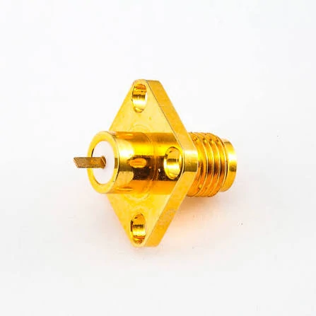
This image shows a standard SMA female connector interface used in RF and microwave applications. The socket center contact and internal thread structure help identify the correct SMA mating interface before selection.
Do not start with the product title. Start with the physical interface.
A standard SMA female connector normally has a socket contact at the center and an internal-thread coupling structure. It mates with a standard SMA male connector, which normally has a center pin and external thread. This is a simple check, but it prevents many wrong orders.
The confusion often comes from catalog wording. Some suppliers use female, jack, receptacle, socket, bulkhead, and panel mount in the same listing. These terms are related, but they do not describe the same thing.
“Female” describes the interface gender. “Jack” or “receptacle” often describes the same mating side. “Bulkhead” and “panel mount” describe how the connector is installed. A cable-side female connector, a PCB female jack, and a bulkhead female connector may all have the same front SMA female interface, but the rear structure is completely different.
For replacement work, check the connector from both sides. The front face tells you what it mates with. The rear body tells you how it installs or terminates.
Recognize the socket contact and internal-thread interface
The first inspection point is the center contact.
If the center contact is a socket and the outer coupling structure has internal thread, the part is usually a standard SMA female connector. If the center contact is a pin and the outer coupling structure has external thread, it is usually SMA male.
This check is more reliable than relying on listing titles. It is especially useful for adapters and cable assemblies, where each end may have a different gender. A product described as “SMA female to SMA male” must be checked end by end.
For custom cable assemblies, the same rule applies. “SMA cable” is not enough. The request should say which end is female, which end is male, what cable type is used, and whether the female side is straight, right-angle, bulkhead, or panel mount.
Check whether the mating side requires SMA male or RP-SMA
SMA and RP-SMA are easy to mix up.
Standard SMA and reverse-polarity SMA can look similar from a distance, especially in small product photos. The thread may appear compatible, but the center contact arrangement is different. A standard SMA female connector should not be treated as interchangeable with an RP-SMA female connector.
This matters for antenna ports, Wi-Fi equipment, GPS devices, routers, RF modules, and test accessories. Some devices use standard SMA. Some use RP-SMA. Some listings describe the connector by thread direction, while others describe it by center contact. That inconsistency creates purchasing risk.
A safer purchase note is:
“Standard SMA female jack, socket center contact, internal thread, mates with standard SMA male plug.”
That sentence removes most of the ambiguity.
| Check Point | Standard SMA Female | Possible Ordering Risk |
| Center contact | Socket contact | Confused with RP-SMA |
| Thread | Internal thread | Thread may look similar |
| Mating side | Standard SMA male | Wrong male counterpart selected |
| Better confirmation | Front-face photo or drawing | Avoid title-only ordering |
The buyer should not approve production only from the words “SMA female.” A front-face photo or mechanical drawing is still the better confirmation.
Confirm whether the part is a jack, receptacle, or cable-side female connector
In RF catalogs, SMA female connector, SMA female jack, and SMA receptacle may refer to the same front interface. The difference is usually the mounting or termination structure.
A PCB mount SMA female jack is used on board-level RF modules. A bulkhead SMA female connector passes through an enclosure wall. A panel mount SMA female connector may use a flange, nut, washer, or threaded body. A cable-side SMA female connector is assembled onto coaxial cable.
These differences affect production. They decide the hole size, PCB footprint, cable OD, soldering method, crimp ferrule, thread length, nut clearance, and inspection method.
| Selection Item | What It Confirms | Why It Matters |
| Interface gender | SMA female socket contact | Confirms mating side |
| Polarity | Standard SMA or RP-SMA | Prevents wrong pairing |
| Mounting style | PCB, bulkhead, panel, cable end | Confirms installation method |
| Termination | Solder, crimp, clamp, PCB pin | Confirms assembly process |
| Cable match | RG316, RG174, RG58, RG142, etc. | Prevents ferrule/body mismatch |
| Electrical requirement | 50 ohm, frequency, VSWR | Prevents RF performance issues |
For sourcing, one clear photo can prevent several emails. A front-face photo confirms gender and polarity. A rear-side photo confirms mounting style. A caliper photo helps confirm panel hole size, thread length, and body diameter when replacing an existing connector.
How Do SMA Female and SMA Male Interfaces Mate Correctly?
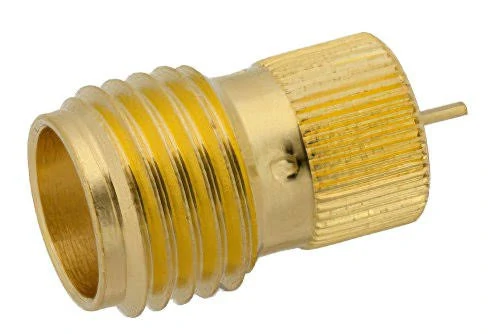
Comparison image of SMA female and SMA male connectors showing the difference between socket and pin contacts. This helps users select the correct RF connector combination for adapters and cable assemblies.
SMA mating should feel controlled. It should not require force.
A standard SMA female connector mates with a standard SMA male connector. The male side provides the center pin and external thread. The female side provides the socket contact and internal thread. When both sides are correct, the thread should engage smoothly before final tightening.
If the connector feels tilted, rough, or unusually tight, stop. The problem may be crossed thread, damaged plating, wrong polarity, bent center pin, or poor mechanical tolerance. Forcing the connection can damage the female socket, especially on equipment ports, test fixtures, and panel-mounted interfaces.
Compare center contact, thread direction, and mating structure
The connector name is less useful than the mating structure.
| Field | SMA Female Connector | SMA Male Connector |
| Center contact | Socket / receptacle | Pin |
| Thread position | Internal thread | External thread |
| Common name | Jack / receptacle | Plug |
| Typical use | Device port, PCB, panel, bulkhead | Cable end, adapter end |
| Mating interface | SMA male | SMA female |
| Common error | Confused with RP-SMA female | Confused with RP-SMA male |
This table should be checked before price, stock, or delivery time. If the interface is wrong, a cheaper connector only creates a faster return.
For cable assemblies, a better order description would be:
“SMA female bulkhead to SMA male straight cable assembly, 50 ohm, RG316 cable, 300 mm length, standard SMA polarity, continuity tested, VSWR test required if used near the target RF band.”
That is much clearer than “SMA cable 30 cm.”
Avoid ordering by gender words alone
“Female” is not enough for RF production.
A connector for RG316 should not be substituted for RG58 only because the front interface is SMA female. The cable diameter, dielectric size, braid contact, ferrule, rear body, and crimp tooling may all be different. The connector may assemble poorly even if the mating face looks correct.
The first sourcing question should be practical:
Where will the SMA female connector sit in the RF path?
If it is mounted on a device wall, check panel thickness, thread length, nut clearance, washer, and sealing requirement. If it is on a PCB, check the footprint, soldering method, grounding, and board edge clearance. If it is on a cable, check cable type, length, flexibility, bend radius, and termination method.
The connector name is only the start of the selection.
How Do You Choose an SMA Female Connector Mounting Style?
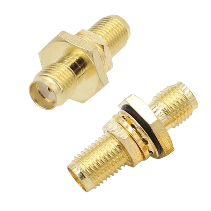
The same SMA female interface can sit in very different mechanical positions.
That is where many purchasing mistakes begin. A buyer confirms the front side, then forgets to confirm how the connector is actually installed. The result may be a correct SMA female interface with the wrong rear body, wrong thread length, wrong PCB footprint, or wrong cable termination.
Mounting style should be confirmed before price comparison.
Select PCB mount female connectors for board-level RF modules
A PCB mount SMA female connector is selected by more than the mating face. The board footprint, grounding pads, center pin position, dielectric support, soldering method, and enclosure clearance all matter.
For board-level RF modules, the connector must match the PCB layout. A straight PCB jack and a right-angle PCB jack cannot be exchanged casually. Even if both are SMA female, the signal launch geometry is different. At higher frequencies, the transition from PCB trace to connector becomes part of the RF path.
A buyer should provide the PCB drawing or an existing sample whenever possible. If the product is being replaced, measure the pin spacing, board edge distance, and mounting leg position. A photo alone may not show whether the center pin lands correctly on the RF trace.
Use bulkhead female connectors for enclosure feedthroughs
A bulkhead SMA female connector is used when the RF path needs to pass through a panel or enclosure wall. The front side may mate with an antenna, adapter, or cable assembly. The rear side may connect to cable, solder terminal, PCB, or another interface.
The key mechanical checks are panel hole diameter, panel thickness, thread length, nut clearance, washer position, and sealing requirement. If the thread is too short, the nut may not lock properly. If the hole is too large, the connector can shift during installation. If the washer or gasket is missing in an outdoor enclosure, sealing may fail even when the RF interface is correct.
For sourcing, do not only write “SMA female bulkhead.” Add the panel thickness and whether the connector needs a washer, O-ring, gasket, or flat mounting face.
Choose panel mount designs for fixed equipment interfaces
Panel mount SMA female connectors are common on test boxes, RF equipment, antenna ports, signal modules, and custom enclosures. Some use a threaded body and nut. Others use a flange with screws. The correct version depends on how the equipment housing is designed.
A threaded bulkhead style is compact and easy to install. A flange style is more stable when the connector may be mated and unmated often. A right-angle rear structure may help when internal cable routing is tight, but it can also add stress if the cable is forced into a sharp bend.
Mechanical stability does not automatically mean RF performance is acceptable. The connector still needs the correct impedance, frequency rating, contact condition, and assembly quality.
| Application | Recommended SMA Female Style | Key Check |
| PCB RF module | PCB mount female jack | Footprint, solder method, RF launch |
| Equipment panel | Panel mount female | Hole size, nut, washer |
| Enclosure feedthrough | Bulkhead female | Thread length, sealing need |
| Antenna interface | Female jack port | Mating male connector or antenna |
| Custom cable | Female cable assembly | Cable OD, length, VSWR |
| Test fixture | Precision female interface | Durability, repeatability |
This matrix should be used as a first filter. After that, the drawing decides the exact part.
How Should You Match SMA Female Connectors With Cable and Assembly Needs?
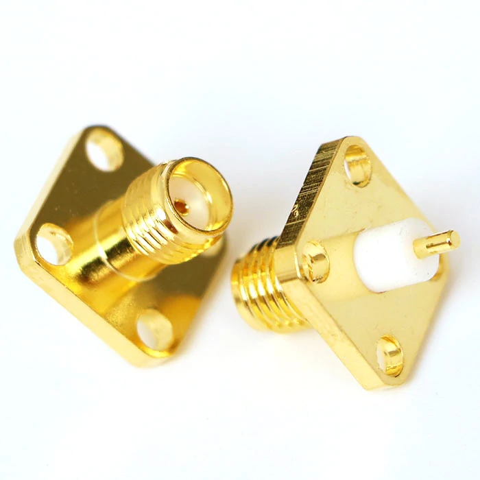
SMA female flange mount connector designed for fixed installation in RF equipment, antenna systems, and microwave applications. The four-hole flange provides stable mechanical mounting.
Cable compatibility is not optional.
A connector made for RG316 should not be treated as a substitute for RG58 or RG142. The SMA female mating face may look the same, but the rear body, ferrule, center pin, insulation support, and crimp area are different. If the cable does not fit the connector body correctly, the assembly may fail mechanically or show poor RF behavior.
Match cable diameter before choosing termination style
Start with cable OD and construction.
Small flexible cables such as RG174, RG178, RG316, and 1.13 mm micro coax need different connector bodies from larger cables such as RG58, RG142, or low-loss coax. Semi-rigid and semi-flexible cables need another structure again.
A wrong rear body can create several problems: loose braid contact, poor crimp compression, damaged dielectric, unstable center conductor soldering, or a weak pull force. The assembly may pass continuity, but the RF path is not stable.
For an RF cable assembly order, write the cable type clearly. Do not only write “SMA female cable.” A better request is:
“SMA female bulkhead to SMA male cable assembly, RG316, 50 ohm, 300 mm, standard SMA polarity, straight rear exit, continuity test required.”
If VSWR or insertion loss matters, add the target frequency and test requirement.
Choose solder, crimp, or clamp termination according to production needs
Termination method affects repeatability.
Crimp termination is common for production cable assemblies because it is faster and more consistent when the tooling is correct. Solder termination may be used for some structures, small batches, repairs, or specific cable types, but heat control becomes important. Clamp structures are used in some larger or special RF connectors where mechanical contact and shielding control need more attention.
For batch production, the supplier should confirm the ferrule size, stripping length, center conductor preparation, braid handling, and final inspection method. A small change in cable source can also change assembly behavior. Two cables with similar names may not have the same OD, braid density, or dielectric size.
This is why procurement should avoid approving substitutions based only on connector interface. The cable and connector must be treated as one RF assembly.
Use female bulkhead cable assemblies for external antenna ports
SMA female bulkhead cable assemblies are often used as external antenna ports on enclosures.
This design is practical, but it needs careful routing. The inside cable should not be pulled sharply against the rear of the connector. Tight bends near the connector body can stress the termination and change RF behavior. If the assembly is used outdoors or near vibration, washer, nut torque, strain relief, and sealing method should be confirmed.
A simple installation note can prevent later issues:
“Install through panel, tighten nut after alignment, avoid twisting the cable during tightening, keep bend radius controlled behind connector.”
How Does Frequency Rating Influence SMA Female Connector Selection?
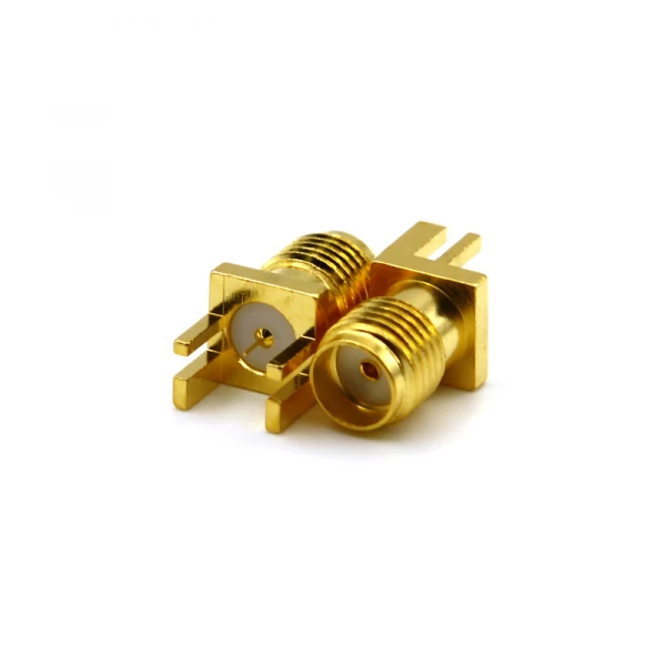
SMA female coaxial cable connector used in 50 ohm RF cable assemblies. Suitable for applications using RG316, RG174, and other coaxial cables in communication and testing systems.
Frequency rating should be checked after the mechanical fit is clear.
A connector that cannot be installed correctly is already wrong. But once the style and cable match are confirmed, the RF requirement decides whether a general SMA female connector is enough.
Verify impedance before checking frequency range
Most standard SMA RF connectors are used in 50 ohm systems. That should still be written in the specification. Do not assume every coaxial part in the purchasing chain is correct just because the interface is SMA.
The RF path includes the connector, cable, adapter, PCB launch, and mating interface. A 50 ohm SMA female connector connected to the wrong cable or a poor transition can still perform badly.
A practical BOM note should include:
“SMA female connector, standard polarity, 50 ohm, suitable for target operating frequency, mounting style confirmed, mating interface confirmed, inspection requirement included.”
Check VSWR and insertion loss for high-frequency systems
At low frequencies, buyers may focus mainly on mating and continuity. At higher frequencies, return loss, VSWR, insertion loss, and repeatable mating become more important.
A useful way to judge margin is:
Frequency Margin Ratio = Connector Rated Frequency ÷ Highest Operating Frequency
| Frequency Margin Ratio | Practical Meaning | Suggested Action |
| Below 1.0x | Rating is lower than use frequency | Do not use |
| 1.0x–1.2x | Very tight margin | Test carefully before approval |
| 1.2x–1.5x | Usually acceptable for general RF links | Check VSWR if sensitive |
| 1.5x–2.0x | Safer for test leads or higher repeatability | Better sourcing choice |
| Above 2.0x | Stronger margin | Useful for demanding RF paths |
This is not a guarantee of performance. It is a sourcing filter. The finished cable assembly still depends on cable loss, connector count, adapter count, bend radius, and termination quality.
Avoid damaging precision ports during mixed-connector mating
SMA connectors are often used around test equipment, adapters, and microwave modules. That environment creates another risk: connector damage caused by repeated mating or careless adapter use.
Before connecting an SMA female port to a test cable or adapter, inspect the thread, center contact, and mating face. Dirt, burrs, tilted contacts, or damaged plating can affect both the connector and the equipment port. For precision measurement work, visual inspection and proper torque control are part of the RF process, not extra steps.
A connector that is “close enough” mechanically may become expensive if it damages a test port.
How Do You Evaluate Bulkhead and Panel-Mount SMA Female Connectors?
A bulkhead SMA female connector usually looks harmless in a catalog photo. Threaded body, nut, washer, female interface. The trouble starts when that same part has to pass through a real enclosure.
One sample may fit a thin test plate. The production box may use a thicker wall. The nut may still catch, but only by two or three turns. Another common issue is rear space. The connector is correct, but the cable has to bend too sharply behind the panel. It passes continuity, then becomes unstable after assembly or vibration.
For panel-mounted parts, check the drawing before checking price.
Check panel hole, thread length, and rear clearance
The panel hole should match the connector drawing. A tight hole can scrape plating or damage the thread during installation. A loose hole lets the connector rotate when the mating cable is tightened.
Thread length is just as practical. A connector that locks well on a 1 mm panel may not work on a 3 mm enclosure. Nut clearance also needs attention. In compact equipment, there may be no room for a wrench, washer, or proper cable bend.
Do not treat washers and gaskets as minor parts
For an indoor test box, a washer may only support locking. For an outdoor antenna enclosure, a gasket or O-ring may be part of the sealing design. If it is required, write it into the BOM. Do not assume it will come with the connector.
This is especially important in batch orders. Connector bodies, nuts, washers, and gaskets should be packed and labeled clearly. Missing accessories can stop the assembly line even when the connector itself is correct.
| Check Item | Buyer Should Confirm | Why It Matters |
| Interface | Standard SMA female, not RP-SMA | Avoids mating error |
| Panel hole | Drawing-matched size | Prevents loose or forced mounting |
| Thread length | Fits actual panel thickness | Allows the nut to lock |
| Washer / gasket | Included if required | Supports mounting or sealing |
| Rear space | Enough bend room | Reduces cable stress |
| RF requirement | 50 ohm and frequency range | Keeps the RF path defined |
How Should You Inspect SMA Female Connectors Before Installation?
The center socket should be clean, centered, and not collapsed. The mating face should not have burrs, dirt, oxidation, or obvious plating damage. The internal thread should start smoothly by hand. If it feels rough, tilted, or unusually tight, stop and check the mating side.
Do not use a wrench to force the first thread engagement. A bent SMA male pin can damage the female socket. A damaged female socket can then create weak contact, unstable repeatability, or poor RF results later. On test fixtures and measurement ports, that mistake can cost more than the connector.
Continuity testing is useful, but it is limited. A multimeter can catch opens and shorts. It cannot confirm VSWR, insertion loss, return loss, or behavior near the working frequency.
For simple internal RF links, appearance and continuity may be enough. For antenna ports, microwave modules, test leads, or repeat production, add RF testing at the actual operating band.
How Do You Prepare RF Purchase Specifications for SMA Female Connectors?
A good RF purchase request is short, but it should not leave room for guessing.
“Please quote SMA female connector” is too vague. The supplier still does not know whether it is standard SMA or RP-SMA, PCB mount or bulkhead mount, cable-side or panel-side, RG316 or RG58, 2.4 GHz or 18 GHz.
A better request sounds like this:
“Standard SMA female jack, socket center contact, internal thread, 50 ohm, bulkhead mount, with nut and washer, mates with standard SMA male plug.”
For PCB versions, add the footprint or drawing. For panel versions, add hole size, panel thickness, thread length, and sealing requirement. For cable assemblies, add cable type, length, connector orientation, and test requirement.
A useful cable assembly request could be:
“SMA female bulkhead to SMA male straight cable assembly, RG316, 300 mm, 50 ohm, standard SMA polarity, continuity tested, VSWR checked at working frequency if required.”
Frequency should be written as a real use condition. If the product works at 2.4 GHz, write 2.4 GHz. If it works at 5.8 GHz, write 5.8 GHz. Do not copy the highest catalog rating unless that is actually the required range.
FAQ
How can I tell if a connector is SMA female?
Check the center contact and thread. A standard SMA female connector usually has a socket contact and internal thread. It mates with a standard SMA male connector. For adapters and cable assemblies, check both ends separately instead of trusting the title.
Is an SMA female connector the same as an SMA jack?
Usually, the terms describe the same front interface. The risk is the rear structure. An SMA female jack may be PCB mount, bulkhead mount, panel mount, or cable-side. The drawing or product photo should confirm that part.
Can an SMA female connector be used on a cable assembly?
Yes. It is common on antenna cables, bulkhead pigtails, and RF test leads. The cable type must be confirmed first. RG316, RG174, RG58, RG142, RG405, and micro coax do not use the same rear connector structure.
What is the difference between SMA female and SMA bulkhead?
SMA female describes the mating interface. Bulkhead describes the installation method. A connector can be both SMA female and bulkhead mount. For bulkhead use, check the panel hole, thread length, washer, gasket, and rear cable space.
Are SMA female connectors always 50 ohm?
Most standard SMA RF connectors are used in 50 ohm systems, but the specification should still say 50 ohm. Cable type, adapter count, termination quality, and PCB launch can also affect the final RF path.
Can SMA female connectors be used for microwave applications?
Yes, but do not approve them by name only. Check frequency rating, VSWR, insertion loss, mating condition, adapter stack, and cable assembly quality. Repeated mating also makes thread and socket condition more important.
What should I provide when ordering SMA female connectors?
Provide gender, polarity, mounting style, mating connector, impedance, frequency range, cable type or PCB requirement, quantity, application environment, and inspection requirement. For replacement work, send photos, drawings, or a sample.
What Should Be Confirmed Before Releasing the Order?
Treat “SMA female connector” as the first line of the request, not the complete request.
Confirm the front interface, then confirm the mounting structure, cable compatibility, impedance, frequency range, and inspection requirement. For production orders, the supplier should know what the connector mates with, how it installs, what cable or PCB it connects to, and how the finished part will be checked.
If the assembly works near the upper frequency range, send the operating frequency, cable type, length, connector count, and RF test target before ordering. That information helps decide whether a general SMA female connector is enough or whether a higher-margin version is safer.
