
A cable assembly can pass a continuity test and still be the wrong RF part.
This happens more often than many purchasing teams expect. The connector mates correctly, the cable length looks right, and the first sample performs normally on a bench test. Problems usually appear later — after the assembly is installed inside a compact enclosure, routed around other components, or tested closer to the upper operating frequency.
SMA connectors are widely used because they provide a compact threaded RF interface for many applications, but the connector body alone does not determine whether an RF connection will work correctly. The cable type, impedance, frequency range, termination method, and assembly quality all affect the final result.
For engineers and buyers selecting an SMA connector, the real question is not only “Which SMA connector should I buy?” It is:
Can this connector, cable, and application work together as one RF path?
Why Are SMA Connectors Widely Used in Modern RF Systems?
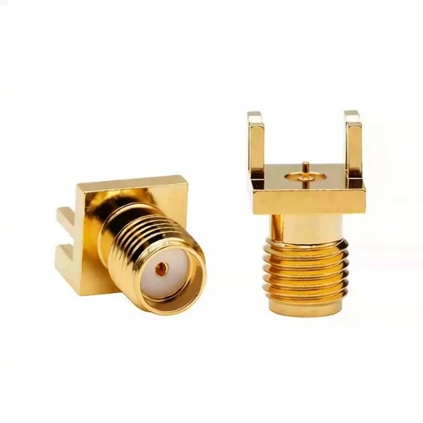
This PCB mount SMA RF connector features a threaded coupling structure and precision contact design. It is widely used in RF modules, wireless communication equipment, antenna systems, and microwave applications requiring reliable 50 ohm connections.
An SMA connector is commonly selected when a system needs a compact 50Ω RF interface with stable mechanical coupling. Compared with larger RF interfaces, SMA provides a smaller connection size while maintaining the threaded structure needed for repeated mating and reliable installation.
Typical SMA applications include:
- RF modules
- wireless communication equipment
- antenna connections
- laboratory test systems
- microwave assemblies
- PCB-based RF designs
The small size is one reason SMA remains popular in compact electronic devices. However, size reduction also means less mechanical margin compared with larger connectors such as N Type connectors.
A designer working on a small wireless module may prefer SMA because the interface occupies less space. A system installed outdoors with repeated mechanical stress may require a different connector family.
The connector selection should follow the complete RF path:
RF Module → SMA Connector → Coaxial Cable → Antenna / Test Equipment
Every part in this chain needs to match:
- connector interface
- impedance
- frequency requirement
- cable structure
- installation environment
A common purchasing mistake is selecting the connector first and trying to adapt the cable afterward.
For example, an SMA connector designed for a thin flexible coax cable cannot simply replace a connector designed for a larger cable diameter. The front mating interface may look identical, but the rear structure, ferrule size, and termination method can be completely different.
Separate SMA Connectors From SMA Adapters Before Ordering
Another common confusion happens between connectors and adapters.
A connector is normally part of the original equipment design.
For a new product design, engineers usually define the connector first. For laboratory testing or equipment compatibility problems, adapters may be the practical solution.
How Do SMA Male and Female Connectors Differ?
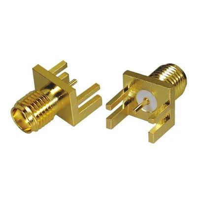
This right angle SMA female PCB connector provides a reliable RF interface for communication devices, wireless modules, and test equipment. The threaded connection design ensures secure mating and stable signal performance.
Many SMA selection problems start with incorrect gender identification.
Two SMA connectors may appear similar in a product image, but the center contact structure determines whether they can mate correctly.
Identify SMA Male Connectors by Their Center Pin Structure
An SMA male connector normally has:
- center pin contact
- external thread
- plug-style mating structure
Male SMA connectors are commonly found on cable assemblies, adapters, and test cables.
The visible center pin is the easiest identification point. However, buyers should not rely only on appearance because some reverse polarity versions use different contact arrangements.
A typical specification should include:
- SMA male
- impedance: 50Ω
- cable type
- mounting style
- frequency requirement
For example, an SMA male plug for RG316 cable is not automatically interchangeable with an SMA male plug for RG58 cable.
The interface side may be the same, but the rear cable termination structure is different.
Identify SMA Female Connectors by Their Socket Structure
An SMA female connector normally includes:
- socket contact
- internal thread
- jack-style mating structure
Female SMA connectors are often used on:
- RF modules
- PCB assemblies
- test equipment ports
- panel-mounted equipment
During procurement, it is better to describe the complete requirement instead of only writing “SMA connector.”
A clearer BOM description would include:
| Item | Specification Example |
| Interface | SMA |
| Gender | Female |
| Impedance | 50Ω |
| Mounting | PCB / panel mount |
| Frequency | Application dependent |
| Termination | Solder / PCB / cable |
This reduces incorrect substitutions during purchasing.
Do Not Confuse Standard SMA With RP-SMA
Standard SMA and RP-SMA look similar but are not interchangeable.
The main difference is the center contact arrangement.
Standard SMA:
- male connector has center pin
- female connector has socket contact
RP-SMA reverses this structure.
This difference is especially important in wireless equipment because a connector that physically screws together may still create an incorrect electrical connection.
Before replacing an SMA connector, confirm:
- connector polarity
- center contact type
- mating equipment specification
A visual check from the outside is not always enough.
SMA Male vs Female Connector Selection Table
| Feature | SMA Male | SMA Female |
| Center Contact | Pin | Socket |
| Thread | External | Internal |
| Common Location | Cable / Adapter | Equipment / PCB |
| Visual Identification | Visible center pin | Recessed contact |
| Typical Use | Cable connection | Device interface |
The correct gender choice is only the first step. Frequency rating, cable compatibility, and assembly method determine whether the connector will perform correctly in the final RF system.
How Does SMA Connector Design Affect RF Performance?
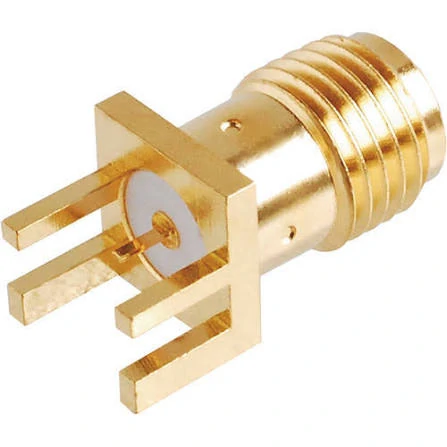
This gold plated SMA male RF connector is designed for high frequency RF applications. It provides stable electrical performance and mechanical durability for wireless communication equipment, RF testing systems, and microwave devices.
Two SMA connectors can look almost identical in a catalog image and still behave differently after they are installed into an RF system.
The difference usually does not appear during a basic continuity check. A multimeter may confirm that the center conductor is connected, but it cannot tell whether the assembly will maintain acceptable RF performance at the working frequency.
This is where many sourcing problems begin.
A connector supplier may quote the same SMA interface, the same 50Ω impedance, and a similar frequency rating. However, the internal structure can vary:
- contact design
- dielectric support
- machining tolerance
- plating process
- cable termination method
These details become more noticeable as frequency increases.
For a low-frequency control signal, a small mechanical difference may not create an obvious issue. In a microwave test setup, the same difference can affect VSWR, return loss, and repeatability between assemblies.
Check the Complete RF Path Instead of the Connector Alone
An SMA connector is only one section of the transmission path.
A typical RF connection includes:
Equipment Port → SMA Interface → Cable Assembly → Antenna or Test Device
If any section changes unexpectedly, the final result may change.
For example, replacing a specified RG316 cable assembly with another cable that has a similar appearance may create several problems:
- different attenuation
- different flexibility
- different connector body requirement
- different bending behavior inside the enclosure
The front SMA interface may still connect normally, but the complete assembly is no longer the same.
For engineering teams, the connector specification should normally include more than the interface name.
A practical RF specification usually contains:
| Specification | Example Requirement |
| Connector Interface | SMA |
| Impedance | 50Ω |
| Gender | Male / Female |
| Cable Type | RG316 / RG174 / RG142 |
| Frequency Range | DC–6 GHz / DC–18 GHz |
| Termination | Crimp / Solder |
| Test Requirement | Continuity / VSWR / Insertion Loss |
This type of information prevents suppliers from making substitutions based only on appearance.
Why Does 50Ω Matching Matter When Selecting SMA Connectors?
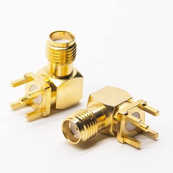
This 50 ohm SMA female bulkhead connector is suitable for coaxial cable assemblies, antenna connections, RF modules, and laboratory test equipment. It provides secure threaded coupling and consistent RF performance.
Most SMA applications are based on 50Ω RF systems.
The reason is not simply because “50Ω is the standard.” The important point is that the connector, cable, and equipment port are expected to maintain similar electrical characteristics.
When impedance changes along the RF path, part of the signal can reflect back toward the source.
Engineers usually observe this through measurements such as:
- VSWR
- return loss
- insertion loss
However, these measurements are affected by the whole assembly, not only the SMA connector.
A connector with a good specification can still produce poor results if:
- the cable preparation is inconsistent
- the center pin is not aligned correctly
- the shielding connection is weak
- soldering introduces excessive heat damage
- the cable is bent beyond its recommended radius
This is why experienced buyers usually evaluate the assembly process, not only the connector datasheet.
How Should You Evaluate SMA Connector Frequency Range?
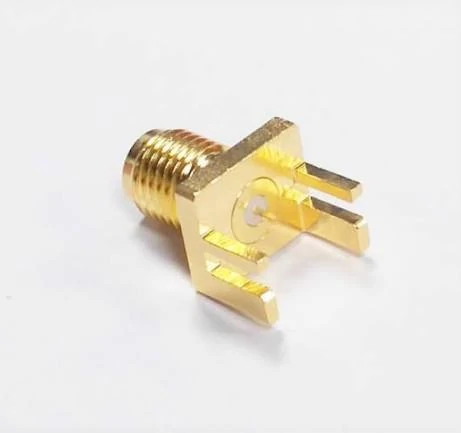
This high frequency SMA PCB RF connector is designed for compact RF equipment requiring reliable signal transmission. It is commonly used in communication systems, RF test fixtures, antenna modules, and microwave applications.
The highest possible frequency number is often the first specification buyers look at.
It should not be the only one.
A 6 GHz SMA connector may be completely suitable for one application and unsuitable for another. The correct choice depends on the actual operating environment.
Consider two examples:
A short SMA cable inside a wireless device may operate around 2.4 GHz.
A laboratory test cable may also use SMA but require stable performance closer to 18 GHz.
Both products use the same interface name. The engineering requirements are different.
When reviewing an SMA connector frequency range, consider:
- operating frequency
- frequency margin
- cable loss
- connector quantity in the RF path
- measurement accuracy requirement
A useful internal selection method is:
Frequency Margin Ratio = Connector Rated Frequency ÷ Maximum Operating Frequency
| Ratio | Practical Use |
| Below 1.2× | Limited margin, review carefully |
| 1.2×–1.5× | Suitable for common RF connections |
| Above 1.5× | Better for test and sensitive RF paths |
| Above 2× | Preferred where measurement stability matters |
This calculation does not replace RF testing. It is only a quick way to avoid selecting a component that is working too close to its limit.
How Do You Match SMA Connectors With Coaxial Cable?
The rear section of an SMA connector is where many ordering errors happen.
The front interface may be identical, but the cable side is different.
An SMA connector for RG316 is not designed the same way as one for RG58 or RG142.
The difference comes from cable construction:
- outer diameter
- dielectric thickness
- conductor size
- shielding layers
- mechanical strength
A mismatch can create problems during assembly:
- poor crimping
- weak cable retention
- damaged dielectric
- unstable electrical contact
Common SMA coax cable applications include:
| Cable | Typical Use | Selection Consideration |
| RG316 | Compact internal wiring | Small diameter, flexible routing |
| RG174 | General RF connection | Balance between size and loss |
| RG178 | Miniature assemblies | Requires accurate termination |
| RG142 | Lower-loss applications | Larger connector structure |
In production, the cable should normally be confirmed before the connector model is finalized.
A purchasing request that only says:
“SMA cable”
leaves too much room for interpretation.
A better request would specify:
“SMA male cable assembly, RG316 coax, 300 mm length, 50Ω, DC–6 GHz, crimp termination, tested before shipment.”
That single sentence gives the supplier enough information to select the correct assembly.
What Should Be Checked During SMA Cable Assembly Production?
The final SMA cable assembly is where component selection becomes a real product.
A sample may pass testing, but production consistency depends on process control.
Important production points include:
- stripping length control
- center conductor positioning
- solder temperature control
- crimp height
- connector tightening condition
- cable routing
For repeated orders, inspection standards are often more valuable than simply requesting a higher specification.
SMA Cable Assembly Selection Matrix
| Application | Suitable SMA Assembly | Main Risk |
| Internal RF module connection | Flexible SMA coax assembly | Cable routing stress |
| Antenna connection | SMA cable with matched coax | Wrong cable substitution |
| RF test equipment | Precision SMA assembly | VSWR variation |
| Prototype development | Solder SMA assembly | Operator consistency |
| Mass production | Crimp SMA assembly | Tooling control |
A reliable SMA assembly is not created by the connector interface alone. The cable structure, termination method, and inspection process all determine whether the final RF path behaves as expected.
For procurement teams, the most useful specification is usually not the shortest one. A complete requirement at the beginning prevents much longer troubleshooting after production starts.
When Should You Use SMA Instead of Other RF Connector Types?
A connector change is rarely just a connector change.
In an RF project, replacing SMA with another interface may affect the cable routing, enclosure design, mounting hole size, test fixture compatibility, and even the supplier’s production process.
This is why experienced engineers usually decide the connector family before finalizing the mechanical design.
SMA is popular because it fits a specific range of applications well:
- compact RF modules
- internal antenna connections
- test equipment interfaces
- microwave assemblies
- laboratory prototypes
However, SMA is not designed for every environment.
A connector used inside a small wireless device and a connector installed on an outdoor antenna system face completely different problems.
The first one may prioritize:
- size
- weight
- flexible cable routing
The second one may prioritize:
- mechanical strength
- weather resistance
- long-term stability
The connector selection should follow the actual working condition, not only the frequency number on the datasheet.
Why Is SMA Often Selected for Compact RF Systems?
Space is usually the first reason engineers consider SMA.
Compared with larger RF connectors, SMA takes less installation space while still providing a threaded connection.
This makes it suitable for equipment where several RF paths may exist close together.
Typical examples include:
- wireless communication modules
- GPS equipment
- RF evaluation boards
- signal measurement fixtures
But compact size also means the mechanical structure has limits.
For example, an SMA cable connected to a small PCB module may work perfectly inside a device enclosure.
The same cable may not be the best choice for an outdoor application where the connector is exposed to:
- repeated movement
- pulling force
- vibration
- weather conditions
The interface name alone does not tell the whole story.
A buyer requesting an “SMA antenna cable” may receive very different products depending on whether the supplier assumes:
- indoor installation
- test equipment use
- vehicle application
- outdoor antenna connection
A few additional details in the specification can prevent unnecessary replacement.
How Does SMA Compare With N Type, BNC, and TNC?
Different RF connectors exist because different engineering problems exist.
SMA, N Type, BNC, and TNC are not simply different sizes of the same connector.
They were developed for different usage environments.
| Connector | Common Application | Typical Advantage | Possible Limitation |
| SMA | RF modules, test systems, compact assemblies | Small size and threaded coupling | Less mechanical strength than larger connectors |
| N Type | Antenna systems, outdoor RF equipment | Strong mechanical structure | Larger installation space |
| BNC | Test instruments, video, quick connection | Fast mating operation | Not usually selected for high-frequency compact designs |
| TNC | Communication equipment, outdoor systems | Threaded connection with stronger structure | Larger than SMA |
A common mistake is replacing connectors based only on whether they can physically connect.
Physical compatibility does not always mean RF compatibility.
Before changing connector types, check:
- impedance
- frequency range
- cable size
- mounting structure
- application environment
A connector replacement that looks simple on a drawing may require changes to the entire assembly.
What Problems Appear During SMA Connector Testing?
Many RF assembly problems are discovered after the product has already entered production.
The reason is simple:
A basic electrical check is not the same as an RF verification.
A continuity test can confirm that the conductor path is connected.
It cannot show:
- impedance variation
- poor termination
- excessive reflection
- frequency-dependent loss
This difference becomes important when working with SMA cable assemblies.
A cable may pass incoming inspection but show unstable results after:
- bending during installation
- repeated mating cycles
- temperature changes
- movement inside equipment
Mechanical Inspection Before RF Testing
Before connecting measurement equipment, production teams usually check the physical condition first.
Typical inspection items include:
- connector thread condition
- center pin position
- solder or crimp quality
- cable damage
- connector locking condition
A damaged thread may seem like a mechanical problem only, but incorrect mating pressure can also affect the RF connection.
RF Verification When Required
For more demanding applications, engineers may use:
- VSWR testing
- insertion loss testing
- return loss measurement
- VNA analysis
The required test level depends on the product.
A short internal cable for a consumer device may only require basic inspection.
A laboratory measurement cable may require much tighter control because the cable itself becomes part of the measurement system.
What Should Buyers Prepare Before Ordering SMA Cable Assemblies?
Many quotation delays happen because suppliers receive incomplete information.
A request like:
“Need SMA cable”
usually leaves several questions unanswered.
The supplier still needs to know:
- Which SMA gender?
- Which cable?
- How long?
- What frequency?
- What application?
- What testing requirement?
A more useful purchasing description would look like:
| Item | Example |
| Connector | SMA male |
| Cable | RG316 coax |
| Length | 500 mm |
| Impedance | 50Ω |
| Frequency | DC–6 GHz |
| Termination | Crimp |
| Application | RF module connection |
This type of information helps avoid the common situation where the first sample works but the production version requires modification.
For custom SMA cable assemblies, cable selection should normally happen before connector confirmation.
The cable diameter determines:
- connector body design
- ferrule size
- termination process
- mechanical strength
How Can You Evaluate an SMA Connector Supplier?
RF connector sourcing is different from buying a standard mechanical part.
The outside appearance may look acceptable while the internal assembly quality varies.
For regular SMA connectors, buyers usually focus on:
- dimensional consistency
- plating condition
- packaging protection
For SMA cable assemblies, more attention is needed on:
- assembly repeatability
- operator process control
- testing method
- batch consistency
A supplier should be able to understand technical requirements instead of only matching a product photo.
For example, these two requests are very different:
“SMA cable”
and
“SMA female bulkhead connector with RG316 cable, 50Ω, 300 mm length, tested for RF application.”
The second request gives enough information for correct evaluation.
SMA Connector Inspection Reference
| Check Point | Why It Matters |
| Interface type | Prevent wrong connector selection |
| Gender | Ensure correct mating |
| Cable compatibility | Avoid termination problems |
| Frequency requirement | Avoid operating near limits |
| Thread condition | Prevent poor connection |
| RF testing | Confirm actual assembly behavior |
FAQ
Can an SMA connector pass continuity testing and still have RF problems?
Yes. A continuity test only confirms that the electrical path is connected. It cannot verify impedance matching, VSWR, return loss, or frequency-related signal loss.
In practical RF assemblies, problems may appear after installation because of cable routing, connector termination quality, bending stress, or operation near the upper frequency limit. For this reason, applications such as RF test cables or microwave assemblies may require additional RF verification.
What details should I send when asking for an SMA cable assembly quotation?
A connector name alone is usually not enough.
For example, “SMA cable” could refer to different products depending on the application. The supplier normally needs to know:
- SMA male or female
- cable type
- cable length
- impedance
- working frequency
- termination method
- application
A clear specification at the beginning usually avoids sample changes later, especially for custom cable assemblies or production orders.
Do I need an 18 GHz SMA connector if my equipment only works at 6 GHz?
It depends on the application.
For a simple RF connection, a connector with enough frequency margin may be sufficient. For test cables, measurement fixtures, or systems where VSWR needs to remain stable, engineers usually leave more margin between the connector rating and the operating frequency.
The connector rating is only one part of the decision.
Can I replace an SMA connector with another model if the interface looks the same?
Not always.
The front mating part may look identical, but the cable side of the connector can be completely different. An SMA connector for RG316 is not necessarily suitable for RG58 or RG142 cable.
The difference is usually inside the rear structure, where the connector has to match the cable diameter, conductor size, and termination method.
Before replacement, check the cable specification instead of comparing only product photos.
