
A cable assembly can pass continuity testing and still be the wrong RF part.
This situation appears more often than many buyers expect. The connector mates correctly, the cable size looks acceptable, and the first sample works on the bench. Problems usually appear later — after the assembly is installed outdoors, exposed to vibration, connected repeatedly during testing, or pushed close to the upper frequency limit.
For RF systems, an n type connector is rarely selected only by interface size. The actual decision involves connector gender, impedance, operating frequency, cable compatibility, mounting method, and the environment where the assembly will be used.
This guide focuses on how engineers and buyers evaluate N Type connectors before placing an order, including common mistakes in connector selection, adapter matching, and RF testing.
How Does an N Type Connector Support Modern RF Systems?
An N Type connector is commonly used in RF systems where mechanical strength and stable threaded connection are more important than minimum size.
Unlike smaller RF interfaces designed mainly for compact modules, N Type connectors are often found in antenna systems, wireless infrastructure, outdoor communication equipment, and RF test setups.
Typical signal paths include:
Antenna → Coaxial Cable → N Connector → RF Equipment
Every part in this path affects the final RF result.
A connector may have a suitable mating interface but still create problems if:
- the cable impedance does not match;
- the connector frequency rating is below the operating band;
- the termination process damages the cable structure;
- the mating parts have poor alignment;
- the installation environment exceeds the connector design limits.
For this reason, N Type selection should start from the complete RF path instead of the connector drawing alone.
Why Do Engineers Still Use N Type Connectors in Antenna Applications?
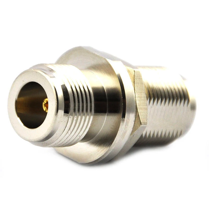
This N Female connector is commonly used in 50Ω RF systems including antennas, wireless communication equipment, and RF test devices. Proper selection requires checking impedance, frequency range, mounting method, and mechanical compatibility.
The main reason is mechanical reliability.
An N connector uses a threaded coupling structure that provides a secure connection compared with quick-lock interfaces.
The connector only becomes part of a reliable system when it matches the cable, frequency range, and installation requirements.
For example, an N connector designed for a large low-loss cable should not simply be replaced with a smaller cable version because the interface looks identical. The rear body, dielectric support, and contact geometry may be different.
Where Does an N Connector Fit in a 50Ω RF System?
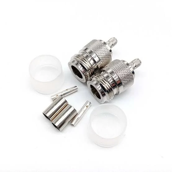
This image shows the internal structure of an N Type connector. The disassembled parts include the connector body, center contact, insulation components, and mechanical elements that affect RF performance, cable compatibility, and assembly reliability.
Most RF applications using N Type connectors are based on a 50Ω impedance system.
If one component does not match, signal reflection can increase.
Important parameters include:
- VSWR (Voltage Standing Wave Ratio);
- return loss;
- insertion loss;
- frequency range.
A connector that performs well at lower frequencies may not maintain the same characteristics near the upper frequency limit.
For example, an N Type connector used at several hundred MHz in an antenna system has very different requirements compared with an N connector used for microwave measurement.
How Do N Male and N Female Connectors Differ?
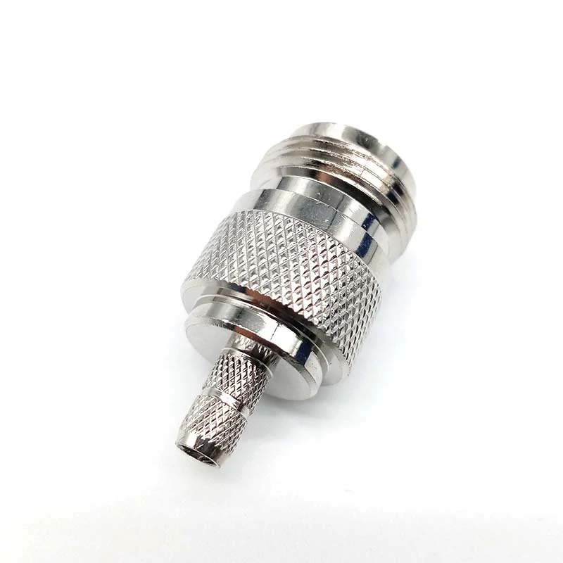
This N Male connector is designed for coaxial cable assembly applications. The threaded interface provides a stable RF connection, while proper cable matching ensures reliable impedance control and signal performance.
One of the most common purchasing mistakes is ordering an N connector based only on the product name.
“N connector” describes a connector family, not a complete specification.
The first detail to confirm is the gender.
How Do You Use an N Male Connector Correctly?
An n male connector usually has a center pin and is commonly installed on the cable side.
Typical applications include:
- coaxial cable assemblies;
- antenna feeder cables;
- RF adapter output interfaces.
When selecting an N male connector for a cable assembly, buyers should confirm:
- cable diameter;
- cable type;
- termination method;
- frequency requirement;
- sealing requirement.
A connector designed for RG58 cable cannot always replace one designed for larger low-loss coaxial cable.
The outer body may look similar, but the internal contact position and cable termination structure can be different.
When Should You Choose an N Female Connector?
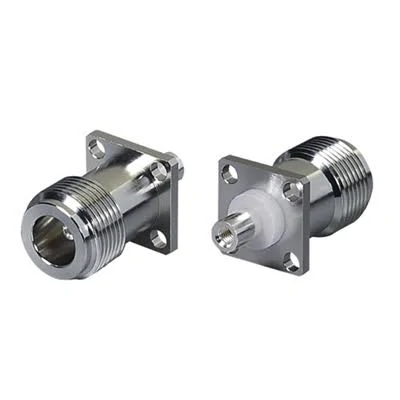
This flange mount N Female connector is designed for equipment panels and RF system integration. The mounting flange provides mechanical stability while maintaining a secure 50Ω connection for antenna systems, communication devices, and test equipment.
Typical installation examples:
- RF equipment ports;
- antenna interfaces;
- panel-mounted connections;
- test equipment interfaces.
For panel applications, additional details should be checked:
- bulkhead or flange mounting;
- mounting hole dimensions;
- sealing method;
- grounding requirements.
A mechanically compatible connector can still create problems if the mounting structure does not match the equipment design.
N Male vs N Female Selection Matrix
| Application Requirement | Recommended Interface | Check Before Ordering |
| Cable assembly connection | N Male connector | Cable type and termination method |
| Equipment panel interface | N Female connector | Mounting style and dimensions |
| Antenna connection | Depends on mating port | Confirm complete RF path |
| Adapter connection | Match both sides | Gender and impedance |
| Custom RF assembly | Follow drawing/specification | Mechanical and electrical requirements |
This simple check prevents a common sourcing problem: receiving a connector that fits mechanically but cannot be integrated into the final assembly.
How Do You Choose an N Type Connector Based on Cable and RF Requirements?
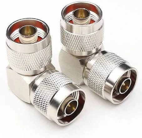
This right angle N Type RF adapter provides a reliable threaded connection for coaxial systems. The angled design helps reduce cable bending stress and is suitable for antenna equipment, communication systems, and RF applications with limited installation space.
A common mistake in RF purchasing is treating the connector as an independent part.
The connector may arrive with the correct N interface, the correct gender, and a matching drawing. However, after the cable assembly is produced, the result may not meet the original requirement.
The reason is simple: the connector is only the transition point between the cable and the equipment.
The actual RF path depends on several connected elements:
- connector structure;
- coaxial cable type;
- cable length;
- termination process;
- operating frequency;
- installation environment.
For an n type connector, the front interface is only the beginning. The rear structure must also match the cable being used.
How Does Cable Compatibility Affect N Type Connector Selection?
Two N connectors can look almost identical from the outside but be designed for completely different cables.
This difference usually appears in the rear section of the connector.
The cable entry diameter, contact design, and termination method must match the coaxial cable construction.
For example:
- a connector for RG58 cable is not automatically suitable for RG142;
- a connector for a flexible cable may not fit a semi-rigid cable;
- a connector designed for small cable diameter may not provide proper shielding contact on a larger cable.
The connection between cable shield and connector body directly affects RF behavior.
If the shield connection is poor, possible issues include:
- unstable impedance;
- increased insertion loss;
- higher VSWR;
- reduced mechanical strength.
For production projects, the cable model should always be included in the connector specification instead of simply writing “N connector”.
A clearer purchasing description would include:
N male connector, 50Ω, for RG58 coaxial cable, straight structure, cable mount, required operating frequency range.
This gives the supplier enough information to select the correct internal structure.
What Cable Factors Should Be Checked Before Ordering?
The connector selection should follow the cable requirements.
| Cable Parameter | Why It Matters |
| Cable diameter | Determines connector rear body compatibility |
| Conductor size | Affects center contact matching |
| Dielectric structure | Influences impedance stability |
| Shielding method | Affects grounding and RF leakage |
| Flexibility | Determines installation suitability |
| Operating frequency | Limits practical RF usage |
A frequent production issue occurs when a cable is changed after the connector has already been selected.
The replacement cable may fit mechanically but create a different electrical condition.
For small quantities this may only appear during testing. For mass production, it can become a repeatability problem.
How Should Frequency Range Be Considered When Selecting N Type Connectors?
The frequency label on a connector is not just a marketing number.
It represents the range where the connector structure can maintain acceptable RF characteristics under specified conditions.
At higher frequencies, small mechanical differences become more noticeable.
Factors that may influence results include:
- center contact alignment;
- dielectric positioning;
- machining tolerance;
- plating condition;
- assembly consistency.
A connector working well at a few hundred MHz does not automatically provide the same result near microwave frequencies.
Why Should Buyers Leave Frequency Margin?
A common sourcing habit is selecting a connector rated exactly at the system frequency.
For example, a project operating near 18 GHz may directly select an 18 GHz connector. This may work in a controlled sample test, but production conditions can introduce additional variables:
- cable routing;
- connector tolerance;
- adapter quantity;
- repeated mating;
- installation stress.
A practical reference is to calculate frequency margin:
Frequency Margin Ratio = Connector Rated Frequency ÷ Maximum Operating Frequency
| Ratio | Suitable Application |
| Around 1.2× | General connection applications |
| Around 1.5× | RF test and measurement cables |
| Around 2× | Sensitive measurement systems |
This ratio is not a replacement for VNA testing. It is a quick screening method during component selection.
How Do N Type Adapters Affect RF System Compatibility?
In many projects, replacing the complete cable assembly is unnecessary.
An n type adapter can provide a faster connection between different RF interfaces.
These adapters are often used in:
- RF laboratories;
- antenna systems;
- communication equipment;
- test setups.
However, adapters should not be treated as invisible components.
Every additional connection introduces another transition point.
The engineer should confirm:
- interface direction;
- male/female combination;
- impedance;
- frequency range;
- mechanical clearance.
What Problems Can Occur With Incorrect RF Adapter Selection?
A physically matching adapter may still be unsuitable.
Typical problems include:
Wrong gender
The adapter cannot connect correctly or requires additional conversion parts.
Wrong impedance
A 50Ω RF system connected with an incompatible interface can introduce mismatch.
Insufficient frequency capability
The adapter may become the limiting component in the RF path.
Excessive adapter stacking
Multiple adapters increase connection points and can affect measurement repeatability.
For RF testing, a shorter signal path with fewer transitions is usually easier to control.
How Do N Type Connectors Perform in RF Testing Applications?
N Type connectors are commonly used in RF measurement because they provide a stable threaded connection and are available for many test configurations.
Typical applications include:
- antenna testing;
- cable verification;
- VNA measurement;
- communication equipment testing.
For measurement work, the connector condition itself becomes part of the test accuracy.
What Should Be Checked Before Using N Type Connectors in Testing?
A connector used repeatedly in a laboratory environment experiences mechanical wear.
Before measurement, engineers usually check:
| Inspection Item | Possible Issue |
| Thread condition | Loose or damaged mating |
| Center contact | Poor electrical contact |
| Connector surface | Contamination or damage |
| Torque condition | Inconsistent connection |
| Cable bending | Internal cable stress |
A connector can still look normal externally while having degraded electrical characteristics.
For repeated VNA measurements, recording connector information is useful:
- connector model;
- cable type;
- frequency range;
- calibration condition;
- test date.
This improves repeatability when the same cable assembly is used across multiple projects.
When Does an N Type Connector Become the Better Interface Choice?
A connector decision is often made before the full installation environment is known.
A design team may select a smaller RF connector during the prototype stage because the space is limited. Months later, the same connection may need to move outdoors, handle longer cables, or survive repeated maintenance.
That is when connector selection becomes a practical engineering issue.
The N Type connector is often chosen in these situations because the connection needs more than just electrical contact. It needs a mechanical interface that can remain stable after installation.
Typical examples include:
- antenna feeder systems;
- outdoor wireless equipment;
- communication infrastructure;
- RF test cables;
- industrial RF links.
The larger body size is not always a disadvantage.
Why Do Outdoor RF Systems Often Use N Type Connectors?
Outdoor RF systems create conditions that are different from laboratory environments.
A connector installed on a bench may only be connected a few times. An antenna connection in the field may experience:
- temperature changes;
- vibration from equipment;
- moisture exposure;
- repeated maintenance;
- cable movement caused by installation stress.
For these applications, the threaded coupling structure of an N Type connector is often preferred.
However, outdoor use does not mean every N connector can be installed outside.
The complete assembly still depends on:
- connector sealing design;
- cable jacket material;
- waterproof treatment;
- installation method.
A waterproof connector with poor cable protection can still fail after long-term exposure.
The cable entry point is usually where environmental protection needs the most attention.
How Should Engineers Compare N Type, SMA, BNC, and TNC?
Different RF connectors solve different problems.
There is no universal replacement between connector families. The interface that works well in a test laboratory may not be the right choice for a communication system.
| Connector | Common Scenario | Main Consideration |
| N Type | Antenna systems and outdoor RF links | Mechanical strength and cable compatibility |
| SMA | Compact RF modules and PCB applications | Small size and high-density installation |
| BNC | Laboratory equipment and quick connections | Fast mating operation |
| TNC | Mobile or vibration environments | Threaded connection with moderate size |
A project using SMA does not automatically need to upgrade to N Type.
Likewise, replacing an N Type connector with a smaller connector only to save space can create new problems:
- unsuitable cable termination;
- weaker mechanical connection;
- reduced environmental tolerance.
The interface should follow the actual working condition.
How Do N Type Adapters Help Connect Different RF Interfaces?
RF systems are rarely built with only one connector standard.
A measurement setup may include:
- an N port antenna;
- an SMA test cable;
- a BNC instrument;
- a TNC communication module.
Replacing all existing cables is usually unnecessary.
An n type adapter provides a transition between different interfaces while keeping the original equipment unchanged.
These adapters are widely used during:
- prototype development;
- RF testing;
- equipment integration;
- maintenance work.
What Details Should Be Checked Before Using an N Type Adapter?
The phrase “N to SMA adapter” does not fully describe the part.
Two adapters with the same interface names may have different specifications.
The following information should be checked:
| Item | Example |
| Connector side A | N male |
| Connector side B | SMA female |
| Impedance | 50Ω |
| Frequency range | Based on application |
| Structure | Straight / right angle |
| Usage | Test / antenna / equipment connection |
The direction also matters.
For example:
- N male to SMA female;
- N female to SMA male;
are different products.
A wrong gender combination may result in additional adapters being added, increasing the number of connection points.
Can Too Many RF Adapters Affect the Signal Path?
Yes.
An adapter solves a mechanical connection problem, but it also creates another RF transition.
A simple connection:
Cable → Equipment
may become:
Cable → Adapter → Adapter → Equipment
Each additional interface introduces another point that may influence:
- insertion loss;
- return loss;
- mechanical repeatability.
For general communication equipment, this may not create a noticeable problem.
For RF measurement systems, especially when using a VNA, unnecessary adapter stacking can make calibration and repeat testing more complicated.
Keeping the RF path simple is usually easier to control.
What Information Should Buyers Include When Ordering N Type Connectors?
Many RF purchasing problems start before production.
The supplier receives a request such as:
“Need 500pcs N connectors.”
The quantity is clear, but the actual product is not.
An N connector request normally needs more information.
What Should Be Written in an N Type Connector Specification?
A practical specification should include:
Interface
- N male or N female;
- connector orientation.
Electrical data
- impedance;
- operating frequency;
- VSWR requirement if needed.
Mechanical data
- cable mount or panel mount;
- straight or right-angle structure;
- mounting dimensions.
Cable information
- RG cable type;
- LMR cable type;
- cable diameter.
Application
- antenna;
- RF equipment;
- testing;
- outdoor installation.
A complete description avoids unnecessary back-and-forth between engineering, purchasing, and suppliers.
For example:
N female bulkhead connector, 50Ω, panel mount, compatible with LMR-400 cable, used for outdoor antenna equipment.
This tells the supplier much more than simply writing “N female connector”.
N Type Connector Pre-Order Review Sheet
Before releasing a purchase order, engineering and purchasing teams can review the following points:
| Check Item | Example Question |
| Interface | Is it N male or N female? |
| Impedance | Is the RF system 50Ω? |
| Cable | Does the connector match the cable model? |
| Frequency | Is there enough operating margin? |
| Installation | Indoor, outdoor, or harsh environment? |
| Mounting | Cable type or panel type? |
| Testing | Is VSWR or insertion loss required? |
| Quantity | Prototype or mass production? |
This type of review is especially useful for custom cable assemblies.
A connector selected correctly at the beginning can reduce later problems during assembly, testing, and field installation.
FAQ
Can an N Type connector be directly connected to an SMA port?
No. The two interfaces are different. An N Type to SMA adapter is normally required, and the adapter specifications should match the RF system.
Why does an N Type cable assembly fail after installation?
Possible causes include incorrect cable matching, poor termination, connector damage, excessive bending stress, or environmental factors. A cable assembly should be evaluated as a complete RF path.
What information should be sent to a supplier before ordering N Type connectors?
At minimum provide connector gender, cable type, impedance, frequency range, mounting style, application, and quantity. More details reduce the risk of receiving a mechanically compatible but unsuitable part.
Why does my N Type connector fit correctly but still have RF problems?
A mechanical fit only confirms that two interfaces can be connected. It does not mean the RF path is working correctly. Problems may come from cable mismatch, incorrect impedance, poor termination, damaged contacts, or using the connector outside its practical frequency range. For RF applications, the connector, cable, and equipment interface should be checked as one complete assembly.
Do N Type adapters introduce signal loss?
Any adapter adds another connection point in the RF path. The actual influence depends on the adapter quality, frequency range, impedance matching, and how many transitions are used. For normal equipment connections, an adapter may be a practical solution.
Final Practical Note
An N Type connector specification should describe the application behind the connector.
For a supplier, “N connector” is only the starting point.
The useful information is:
- where it will be installed;
- what cable it connects to;
- what frequency it carries;
- what environment it operates in;
- what inspection standard is expected.
A complete specification helps prevent problems that cannot be discovered by looking at the connector alone. In RF systems, the connection is only as good as the entire path around it.
