
The adapter was installed correctly, but the measurement result was still different from the expected value.
This situation happens more often than many engineers expect. The SMA port on the RF module fits the adapter, the BNC side connects to the test instrument, and the signal appears. From a mechanical point of view, everything looks normal.
The problem usually appears when the test moves from a quick bench check to a more controlled RF measurement.
A connector adapter changes the signal path. The additional interface introduces another mechanical joint, another contact area, and another possible source of mismatch. For low-frequency checks this may not attract attention, but at higher frequencies the details become harder to ignore.
A properly selected SMA to BNC adapter should match the connector gender, impedance, frequency range, and the equipment being connected.
How Does an SMA to BNC Adapter Fit Into an RF Test Connection?
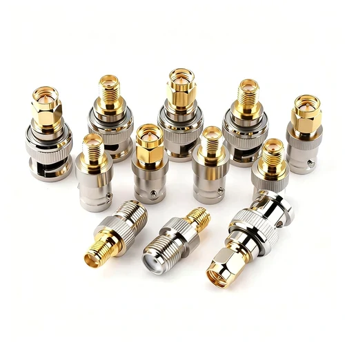
Different SMA to BNC adapter configurations designed for RF testing and measurement equipment. Proper selection of connector gender, impedance, and frequency range helps maintain reliable signal transmission.
SMA and BNC often appear in different parts of an RF system.
A typical development setup may include an RF module with an SMA connector, a coaxial cable, and a measurement instrument with a BNC input. The engineer may not control the connector choice on both sides because the hardware has already been designed.
The adapter becomes the transition point between two connector standards.
The adapter solves the interface problem, but it does not automatically solve every RF compatibility issue.
A frequent purchasing mistake is selecting an adapter only by the names of the connectors. For example, an SMA-to-BNC connection may look correct, but the actual requirement could be:
- SMA male to BNC female
- SMA female to BNC male
- 50Ω RF BNC instead of 75Ω video BNC
- DC to a specific GHz range
- straight body or right-angle structure
The direction of conversion depends on the actual ports, not the search keyword.
A buyer searching for “SMA to BNC adapter” may still need a different physical configuration after checking the equipment drawings.
Why Are SMA and BNC Frequently Used Together?
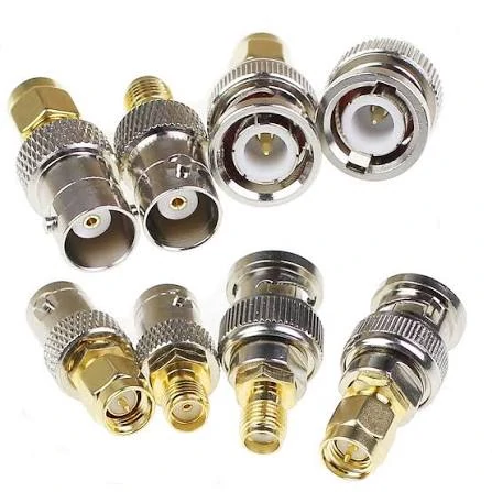
A selection of SMA to BNC RF adapters showing different connector genders and structures. These adapters provide conversion between SMA and BNC interfaces for laboratory testing, RF measurement systems, and communication equipment.
The reason is mainly related to how different equipment is designed.SMA connectors are widely used on compact RF hardware. Replacing the connector on the hardware is usually impossible or unnecessary, so an adapter provides a practical solution.
However, the adapter should be treated as part of the measurement setup.
A short adapter with good specifications may work well in a laboratory test. The same adapter may create problems when combined with a longer cable, multiple conversions, or operation near the frequency limit.
How Should Engineers Check SMA and BNC Interface Compatibility?
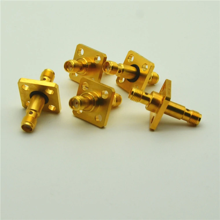
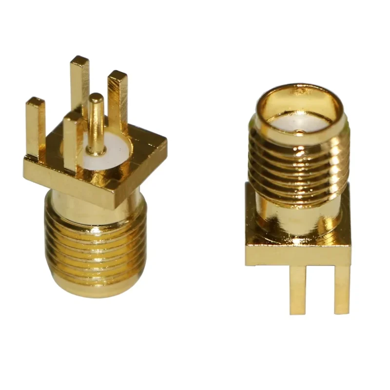
Gold plated SMA flange adapter connectors designed for RF and microwave applications. The flange mounting structure provides mechanical stability while maintaining signal transmission performance.
The connector shape is only the first check.
Before selecting an adapter, confirm the mechanical and electrical requirements together.
Check the connector gender before ordering
SMA and BNC both have male and female versions.
For SMA:
- male side normally has an external thread and center pin
- female side normally has an internal thread and socket
For BNC:
- male side uses the bayonet locking structure
- female side contains the mating interface
A common mistake is ordering the correct conversion direction but the wrong gender combination.
For example:
“SMA to BNC” does not describe the complete part number.
A procurement specification should be closer to:
SMA male to BNC female adapter, 50Ω, DC–6GHz, for RF laboratory connection.
This description gives the supplier enough information to confirm the actual structure.
Confirm whether the RF system uses 50Ω or 75Ω
BNC creates another common confusion because the connector family is used in both RF and video applications.
The mechanical interface may look similar, but the electrical system can be different.
Typical RF systems use:
- 50Ω SMA
- 50Ω BNC
Some video systems use:
- 75Ω BNC
Connecting a 50Ω SMA system with an unsuitable 75Ω BNC component may introduce impedance mismatch.
The connector may still lock correctly, but the measurement result may not represent the actual RF device performance.
This is especially important for:
- VNA measurements
- antenna testing
- signal integrity checks
- frequency response testing
Check the cable before judging the adapter
Another sourcing trap is blaming the adapter when the cable assembly is the limiting factor.
The final RF path depends on:
- adapter quality
- cable type
- cable length
- connector termination
- bend condition
- operating frequency
For example, an adapter rated for a higher frequency does not improve a cable with excessive attenuation or poor termination.
In practical RF testing, the connector is only one part of the system.
SMA vs BNC Interface Comparison Before Selecting an Adapter
The following comparison helps engineers quickly identify the role of each connector.
| Item | SMA | BNC |
| Locking method | Threaded coupling | Bayonet locking |
| Main advantage | Compact RF connection | Fast installation |
| Common equipment | RF modules, microwave devices | Test instruments |
| Typical environment | Embedded RF systems | Laboratory testing |
| Connection style | Fixed threaded connection | Frequent mating |
SMA is usually selected when space and RF frequency requirements are important.
BNC is often selected when engineers need quick access to test equipment.
Neither connector is universally better. The correct choice depends on the system purpose.
For an adapter application, the important question is not “Which connector is better?” but:
“Does this adapter maintain the required RF path between these two specific devices?”
That question usually leads to the correct specification.
Why Does 50Ω Matter When Selecting an SMA to BNC Adapter?
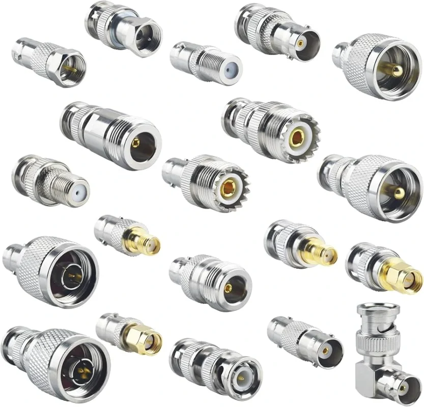
A BNC connector can be the reason a test setup works smoothly, or the reason a measurement becomes confusing.
The difficulty is that the connector itself usually does not show the problem. The adapter can be installed, the instrument can detect a signal, and a basic continuity check can pass.
The issue appears when the measurement requires accuracy.
Most RF systems using SMA connectors are built around a 50Ω impedance environment. That includes many RF modules, antenna systems, communication boards, and laboratory test setups.
When a BNC interface is introduced into this system, the BNC side also needs to match the same electrical condition.
A common mistake during sourcing is focusing only on the mechanical conversion:
“SMA side fits. BNC side fits. The adapter should work.”
That assumption is risky for RF applications.
The actual specification needs to consider:
- impedance
- frequency range
- cable type
- equipment interface
- measurement requirement
A simple adapter used between two bench instruments may have different requirements from an adapter used in antenna measurement.
Why can the wrong BNC specification cause unexpected results?
BNC is widely used in several industries.
The same external connector family can appear in:
- RF test equipment
- communication systems
- video equipment
- instrumentation
However, these applications do not always use the same impedance.
For RF measurement, 50Ω BNC is commonly required.
A 75Ω BNC component may physically connect but create an impedance transition in a 50Ω system.
The result depends on the frequency and the sensitivity of the application.
For a general signal check, the difference may not be obvious.
For a VNA measurement, antenna tuning, or filter verification, the effect can become visible in:
- return loss
- VSWR
- reflection measurement
This is why experienced buyers usually include “50Ω” directly in the purchase specification instead of only writing “BNC adapter”.
A clearer request would be:
SMA female to BNC male RF adapter, 50Ω impedance, used for laboratory measurement equipment.
That description reduces unnecessary back-and-forth between buyer and supplier.
How Should Frequency Range Be Evaluated Before Ordering an SMA to BNC Adapter?
Frequency is another area where specifications are often misunderstood.
A connector marked with a certain frequency rating does not mean the complete RF connection will automatically achieve the same result.
The actual signal path includes:
- SMA interface
- adapter structure
- BNC interface
- cable
- equipment port
Each section contributes to the final measurement.
For example, a short adapter used at 1 GHz in a development environment may have no noticeable issue.
The same adapter installed with a longer coaxial cable and used close to the upper operating limit may show different behavior.
This is why RF engineers usually leave some margin between the operating frequency and the rated frequency.
A practical evaluation method:
| Application | Frequency consideration | Additional check |
| General signal connection | Operating frequency below adapter limit | Confirm connector compatibility |
| Wireless development | Leave frequency margin | Check cable specification |
| RF measurement | Avoid working near limit | Verify VSWR and insertion loss |
| Precision test system | Use verified RF data | Perform VNA measurement |
The adapter rating is only the starting point.
The cable often becomes the limiting factor before the connector itself.
For example, replacing a short test adapter with a longer cable assembly can change the insertion loss significantly, even when the connector remains unchanged.
How Can an SMA to BNC Adapter Affect VNA and RF Testing?
A continuity test answers one question:
“Is there an electrical connection?”
RF testing asks different questions:
“How much signal is reflected?”
“How much signal is lost?”
“How stable is the measurement?”
Those are not the same.
An adapter introduces another transition point in the RF path. The internal contact structure, machining accuracy, dielectric material, and assembly quality all influence the result.
For normal laboratory connection, a small amount of additional loss may be acceptable.
For calibration-sensitive applications, engineers usually pay closer attention.The first measurement uses a short adapter directly connected to the instrument and looks normal.
Later, production testing uses a different cable arrangement. The result changes.
The first reaction is often to check the module.
However, the difference may come from:
- adapter replacement
- cable length change
- connector wear
- different mating condition
Keeping adapter information with the test setup helps avoid this type of confusion.
Record:
| Test item | Example record |
| Adapter model | SMA female to BNC male |
| Impedance | 50Ω |
| Frequency range | DC–6GHz |
| Cable used | RG316 / RG58 / test cable |
| Instrument | VNA / Generator |
| Test date | Record for repeatability |
This information is useful when the same test needs to be repeated months later.
When Is an Adapter Better Than an SMA to BNC Cable Assembly?
The choice between an adapter and a cable assembly depends on how the connection will be used.
For temporary laboratory work, an adapter is usually convenient.
Typical situations:
- prototype debugging
- engineering samples
- equipment comparison
- short-term testing
The advantage is flexibility.
An engineer can quickly change the connection without preparing a new cable.
However, adapters are not always the best choice for permanent setups.
A small SMA connector mounted on a PCB is mechanically limited.
The cable can be selected according to:
- required length
- flexibility
- attenuation
- shielding
- bend radius
The connector transition becomes part of a controlled assembly instead of an added component.
Adapter or cable assembly? A practical decision
| Working condition | Recommended choice |
| Short laboratory test | Adapter |
| Frequent equipment changes | Adapter |
| Production test fixture | Cable assembly |
| Long cable connection | Cable assembly |
| Sensitive RF measurement | Prefer tested assembly |
There is no universal answer.
The better choice depends on whether the priority is flexibility or repeatability.
What Should Be Checked Before Accepting an SMA to BNC Adapter?
Many adapter problems can be avoided before the first installation.
A basic incoming inspection should confirm:
RF Adapter Receiving Check
| Check point | Confirmation |
| SMA interface | Correct gender and structure |
| BNC interface | Correct gender and locking style |
| Impedance | 50Ω requirement confirmed |
| Frequency range | Matches application |
| Mechanical condition | No damage or loose parts |
| Mating condition | Smooth connection |
| Test requirement | Defined before use |
For general applications, visual inspection and mechanical checking may be enough.
For RF measurement applications, additional verification may be required.
The important point is to define the acceptance requirement before ordering.
A supplier can provide an adapter that looks correct, but the final application determines whether it is suitable.
That difference is especially important when the adapter becomes part of a repeatable RF test system.
Where Does an SMA to BNC Adapter Fit Compared With Other RF Connector Conversions?
An SMA to BNC adapter is usually selected because two existing devices need to be connected. The conversion is often decided after the equipment has already been chosen.
This is different from selecting a connector for a new design.
For a new RF product, engineers can decide the interface at the beginning.
For testing or equipment integration, the connector on both sides may already be fixed.
A laboratory may have a BNC-based signal generator.
A development board may only provide an SMA output.
The adapter becomes the practical link between them.
Other RF conversions follow the same logic.
The question is not which connector is more common. The question is what the existing system requires.
Why do some systems use N Type instead of SMA or BNC?
They are commonly found in:
- antenna systems
- wireless communication equipment
- outdoor RF installations
Compared with SMA, N Type has a larger structure.
That size difference is not a disadvantage in many applications. It can be useful when the connector needs to handle larger cables or more mechanical stress.
A small RF module inside a test fixture may use SMA.
An antenna feed line installed outdoors may use N Type.
The adapter selection follows the equipment environment.
A common mistake is replacing one connector standard with another only because both are available. The cable size, mounting condition, and operating frequency still need to be checked.
| Situation | Common choice | What needs checking |
| RF module measurement | SMA to BNC | Instrument interface |
| Outdoor antenna connection | N Type | Weather and cable size |
| Communication equipment | N Type / SMA | Frequency and installation |
| Bench test setup | SMA/BNC conversion | Measurement requirement |
When would PL259 or SO239 conversions appear?
They are different from the smaller SMA systems used in many RF modules.
A typical application may involve:
- amateur radio equipment
- antenna matching systems
- legacy communication devices
A buyer may search for a PL259 to SMA adapter because two devices use different connector standards.
The mechanical conversion may be straightforward.
The RF evaluation is not.
Before selecting the adapter, check:
- operating frequency
- cable type
- impedance requirement
- installation environment
A solution that works for a low-frequency radio setup may not be suitable for a higher-frequency RF measurement path.
The connector name alone does not describe the complete application.
How Are SMA to BNC Adapters Used During Real RF Testing?
The adapter is often introduced during development rather than final product design.
A typical situation:
An engineer receives a new RF module sample.
The module has an SMA connector.
The available laboratory equipment uses BNC ports.
The quickest way to start testing is adding an SMA to BNC adapter.
At this stage, the adapter provides convenience.
The engineer can check:
- signal presence
- waveform
- output level
- basic communication behavior
Later, if the project moves into detailed RF validation, the same connection may need additional verification.
For example:
A signal exists, but the measured output level is different from another test setup.
The possible causes may include:
- different adapter model
- different cable length
- worn connector contact
- changed calibration condition
This is why experienced teams record the test setup instead of only recording the final measurement value.
A useful test record includes:
| Record item | Example |
| Adapter type | SMA female to BNC male |
| Cable | RG316, 500 mm |
| Equipment | RF generator |
| Frequency | 2.4 GHz |
| Test purpose | Output measurement |
The same hardware combination can then be reproduced later.
What Should Be Written in an RF Adapter Purchase Specification?
Many supplier questions start with an incomplete request.
For example:
“Need SMA BNC adapter, 100pcs.”
The supplier still needs to confirm several details.
A complete specification normally includes:
- SMA side gender
- BNC side gender
- impedance
- frequency range
- structure
- application
A practical purchase description:
SMA female to BNC male adapter, 50Ω, straight type, for RF laboratory testing.
For more demanding applications:
SMA female to BNC male adapter, 50Ω, DC–6GHz, used with VNA test setup.
The second description gives more useful information because it explains where the adapter will be used.
This reduces the risk of receiving a mechanically correct but electrically unsuitable part.
What Problems Should Be Checked When an SMA to BNC Connection Does Not Work?
When a signal disappears after adding an adapter, replacing the adapter immediately is not always the fastest solution.
The fault may come from several places.
A practical troubleshooting order:
Check the connector combination
Confirm:
- SMA male or female
- BNC male or female
- correct mating direction
A similar-looking connector does not always mean compatible.
FAQ
Can an SMA to BNC adapter be used directly on a VNA?
It can be used if the interface, impedance, and frequency range are suitable.
For VNA testing, the adapter becomes part of the measurement path. Calibration conditions should include the adapter or the measurement should account for its effect.
Why does the connection work at low frequency but fail at higher frequency?
Higher frequency applications are more sensitive to small discontinuities.
What information should I send when asking for an SMA to BNC adapter quote?
Provide:
- SMA gender
- BNC gender
- impedance
- frequency
- quantity
- application
- cable requirement if applicable
A clear specification allows the supplier to recommend a suitable structure instead of guessing from the connector name.
The product description says “SMA to BNC adapter”. How do I know which model I actually need?
The name alone does not identify the complete adapter.
Before ordering, check the actual ports on the two devices.
For example, these are different parts:
- SMA male to BNC female
- SMA female to BNC male
The application also matters. A part used for a general signal connection may not be the same requirement as one used with a VNA or RF measurement system.
When asking for a quotation, it is better to provide a photo of the equipment port or include the connector gender, impedance, and frequency requirement.
Why does my SMA to BNC adapter connect normally but the RF test result is not the same as before?
This usually means the connection is working mechanically, but something in the RF path has changed.
The adapter is only one part of the setup. A different cable, another adapter batch, connector wear, or even a different mating condition can change the measurement result.
This situation is common when a prototype setup is moved to a production test environment. The engineer may keep the same instrument but change the cable or adapter, and the measured value shifts.
For repeatable testing, it is better to record the adapter model, cable specification, and test condition together instead of treating the adapter as a simple connector change.
Final Selection Notes for SMA to BNC Applications
Most adapter problems happen before the adapter is even installed.
The issue usually starts with an incomplete specification.
For engineering samples, a simple SMA to BNC conversion may solve the connection problem quickly.
For repeatable testing or production use, more details are needed:
- connector configuration
- RF impedance
- operating frequency
- cable condition
- measurement requirement
An adapter is small, but it becomes part of the RF path.
Treating it as part of the system usually leads to better test consistency and fewer unexpected results.
