
A BNC adapter can solve a connection problem in seconds. It can also create an RF problem that is difficult to find.
A signal generator uses a BNC output, but the module under test has an SMA input. A laboratory oscilloscope needs to connect with a different probe interface. A prototype antenna system combines BNC equipment with N-Type components. In these situations, engineers often reach for an adapter because the mechanical connection seems straightforward.
The connector fits. The system powers on. The measurement starts.
Then the unexpected result appears.
The signal level is different from previous tests. The VSWR is higher than expected. A VNA sweep shows additional reflection. The problem may not come from the instrument or cable. The BNC adapter itself has become part of the RF path.
A suitable BNC adapter is not only a mechanical conversion component. It must match the connector interface, gender, impedance, frequency range, and application environment. This guide explains how engineers select BNC adapters for RF conversion, laboratory testing, antenna systems, and coaxial connections.
How Does a BNC Adapter Connect Different RF Interfaces?
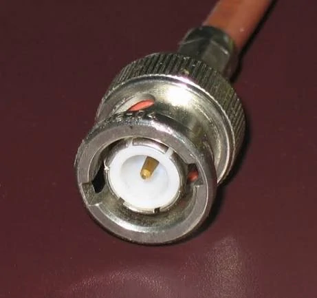
This BNC coaxial connector adapter is designed for RF signal transmission applications. Proper impedance matching and connector selection help reduce signal reflection and maintain stable RF performance.
RF systems rarely use only one connector standard throughout the entire design.
A laboratory may contain:
- BNC test instruments
- SMA RF modules
- N-Type antenna interfaces
- UHF radio equipment
- coaxial cable assemblies with different connector ends
A BNC adapter provides a transition between these interfaces without replacing the existing equipment or cable assembly.
Common applications include:
- SMA to BNC adapter conversion
- BNC to SMA adapter connection
- BNC to N adapter transition
- BNC to UHF adapter connection
- RF measurement setup adjustment
For engineers, the purpose of an adapter is usually simple: connect two incompatible interfaces while keeping the signal path usable.
However, the adapter should be selected as part of the whole RF system rather than as an isolated component.
A connector that fits mechanically may still have problems if:
- the impedance is incorrect
- the frequency rating is insufficient
- the connector gender does not match
- the adapter quality affects repeatability
For example, a 50Ω BNC adapter used in a VNA test setup has different requirements from a general-purpose adapter used for low-frequency laboratory equipment.
Before selecting an adapter, confirm the following parameters:
| Parameter | Reason for Checking |
| Connector interface | Confirms both sides can mate correctly |
| Male/Female type | Prevents incorrect installation |
| Impedance | Avoids mismatch problems |
| Frequency range | Ensures RF compatibility |
| Application | Defines required precision level |
A common procurement mistake is describing the requirement only by appearance, such as “BNC converter” or “BNC connector adapter.” This description is usually not enough for RF applications.
A complete requirement should identify the input connector, output connector, gender, impedance, frequency range, and intended use.
How Do You Choose the Correct BNC Adapter Direction?
The conversion direction is one of the first details engineers need to confirm.
A sma to bnc adapter and a bnc to sma adapter may perform a similar interface transition, but the actual connector arrangement determines whether the adapter works with the existing equipment.
Match SMA to BNC adapters with the equipment connection
SMA to BNC adapters are commonly used when an SMA-based RF component needs to connect with BNC laboratory equipment.
Typical combinations include:
- SMA male to BNC female
- SMA female to BNC male
The correct selection depends on the ports being connected.
For example:
A test cable with an SMA female connector cannot connect directly to another SMA female port. The adapter must provide the correct mating structure on both sides.
Engineers should confirm:
- equipment connector type
- cable connector type
- adapter gender
- impedance standard
- operating frequency
The external shape alone does not define compatibility.
Select BNC to SMA adapters for mixed test environments
A bnc to smaadapter is often used when older test equipment needs to connect with newer RF modules.
Typical applications include:
- oscilloscopes
- signal generators
- RF evaluation boards
- antenna testing systems
- laboratory fixtures
This type of conversion is especially common during prototype development, where different generations of equipment may exist in the same test environment.
The adapter should also match the measurement requirement. A simple connection for signal observation may not require the same specification as a calibration setup or production RF inspection.
BNC Adapter Direction Selection Table
| Application Scenario | Recommended Adapter | Key Check |
| SMA equipment connected to BNC instrument | SMA to BNC adapter | Confirm SMA gender |
| BNC instrument connected to SMA module | BNC to SMA adapter | Confirm frequency range |
| Antenna interface conversion | BNC to N adapter | Check impedance |
| Radio equipment connection | BNC to UHF adapter | Confirm equipment standard |
| RF measurement setup | Precision BNC adapter | Check VSWR and repeatability |
Selecting the correct direction before ordering reduces unnecessary returns and avoids test setup delays. In RF environments, a small interface mistake can affect the entire measurement chain.
How Do 50 Ohm and 75 Ohm BNC Adapters Differ?
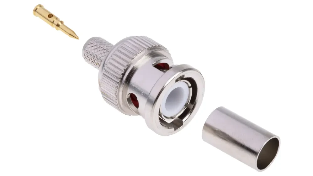
This image illustrates the structure and assembly components of a BNC connector. Understanding connector construction helps engineers evaluate RF adapters for performance, reliability, and compatibility.
A BNC adapter can look correct, connect correctly, and still be electrically wrong.
This happens most often when engineers mix 50Ω and 75Ω BNC systems. The mechanical interface is similar, so the mistake is easy to make during sourcing or equipment setup. The bayonet locking structure allows connection, but the impedance standard inside the RF path may not match.
For general laboratory work, this difference may not always be obvious. During RF measurement, however, impedance mismatch can create reflection, increase measurement uncertainty, and affect the accuracy of the test result.
The first specification to confirm when selecting a BNC adapter is not the outside appearance. It is the impedance.
Match 50 Ohm BNC adapters with RF measurement systems
Most RF test environments use 50Ω systems because instruments and components are designed around controlled impedance transmission lines.
Typical applications include:
- VNA testing
- spectrum analyzers
- RF signal generators
- communication equipment
- prototype RF modules
A 50Ω BNC adapter is commonly selected when maintaining the expected RF path between equipment is important.
For example, when connecting a BNC-based test instrument to an SMA RF component, the adapter should maintain the same impedance standard as the connected system.
A suitable adapter selection should consider:
- connector interface
- impedance
- operating frequency
- VSWR requirement
- measurement purpose
A common mistake is selecting an adapter only because both sides physically connect. In RF testing, the connection itself is only the first requirement.
Use 75 Ohm BNC adapters for video and broadcast systems
75Ω BNC adapters are generally associated with systems where video and broadcast signals are transmitted.
Typical applications include:
- CCTV systems
- broadcast equipment
- CATV systems
- video transmission equipment
These systems use a different impedance environment from many RF measurement applications.
A 75Ω BNC adapter may be completely suitable for a video application but inappropriate for a 50Ω RF test setup.
The issue is not connector size or locking method. The issue is how the RF energy behaves through the transmission path.
Avoid mixing impedance standards even when connectors fit
The following comparison helps explain why impedance should be confirmed before ordering.
| Impedance Standard | Typical Application | Main Selection Concern |
| 50Ω BNC adapter | RF testing, communication equipment, laboratory measurement | Maintain RF matching |
| 75Ω BNC adapter | Video, CATV, broadcast systems | Maintain video transmission standard |
When a 50Ω system is connected with an unsuitable 75Ω component, possible results include:
- increased reflection
- signal degradation
- inaccurate measurement
- unexpected system behavior
For engineering teams, this is also a procurement issue. A purchase request should not only state “BNC adapter.” It should specify:
BNC interface + gender + impedance + frequency range + application
This prevents suppliers from selecting a mechanically compatible but electrically unsuitable part.
How Does a BNC Adapter Affect RF Performance?
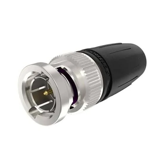
This BNC adapter is designed for RF interface conversion applications. It provides a mechanical and electrical connection between different coaxial connector types, helping engineers connect laboratory instruments, communication equipment, and antenna systems.
An adapter adds another interface into the transmission path.At low frequencies, the influence may be small.
Before selecting an adapter, confirm:
- maximum operating frequency
- required measurement accuracy
- connector construction
- intended RF environment
For example, an adapter used in a general laboratory connection may have different requirements from one used in a VNA calibration setup.
The connector interface alone does not determine the usable frequency range.
The complete RF path includes:
- adapter
- cable
- connector termination
- equipment port
All parts must work together.
How Should You Select BNC Adapters for Different RF Equipment?
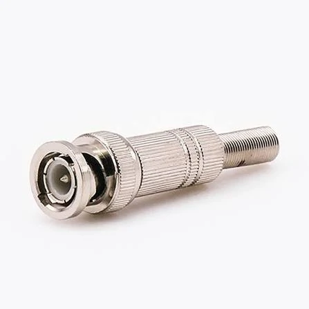
This BNC to SMA adapter provides a compact solution for converting between BNC and SMA connector interfaces. It is commonly used in RF testing, signal measurement, antenna systems, and electronic equipment connections.
A test engineer using a VNA may focus on VSWR, repeatability, and calibration stability.
The same BNC adapter category can have very different selection criteria depending on the application.
Choose BNC adapters for oscilloscope and laboratory instruments
Oscilloscopes are one of the most common applications for BNC interfaces.However, if the oscilloscope is being used for RF measurements, the adapter specification becomes more important.
Select BNC adapters for VNA and RF testing environments
VNA applications require more attention because the instrument measures RF characteristics directly.
When Should You Use a BNC Adapter Instead of a Cable Assembly?
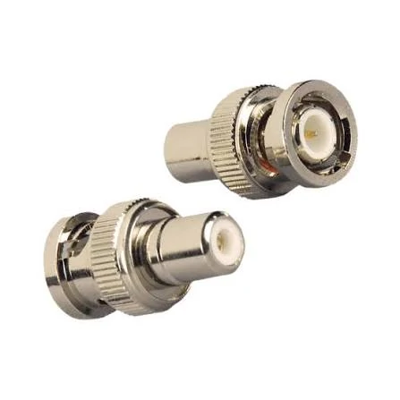
This image shows BNC adapter connectors with different gender configurations. Selecting the correct male or female interface ensures proper mating compatibility and stable signal transmission in RF systems.
For example, a BNC output from a signal generator may need to connect with an SMA input on an evaluation board. A BNC adapter can provide the connection immediately.
For temporary testing, this approach is practical.
The situation changes when the connection becomes part of a production system.
An adapter introduces another mating point. In some applications, this is acceptable. In others, the additional interface becomes a possible source of variation.
The decision between an adapter and a cable assembly depends on how the connection will be used.
Use BNC adapters when flexibility matters during development
Engineering laboratories often have equipment from different generations.
One bench may include:
- older BNC-based instruments
- newer SMA RF modules
- different coaxial cable assemblies
- evaluation boards from multiple suppliers
Replacing every cable to match every device is inefficient.
Typical situations include:
- prototype verification
- signal checking
- troubleshooting
- temporary measurement setups
- equipment comparison
For these applications, the main value is flexibility.
A test engineer may use a BNC to SMA adapter today for one evaluation board and replace it with another adapter tomorrow for a different module.
However, the adapter specification still matters.
A low-frequency laboratory connection and an RF measurement setup are not the same requirement.
Before selecting the adapter, confirm:
- connector gender
- impedance
- operating frequency
- cable interface
- measurement purpose
The adapter should match the actual test condition rather than only the connector shape.
Replace adapter combinations with cable assemblies for fixed installations
A common situation in prototype testing is using several adapters together:
BNC cable → BNC adapter → SMA adapter → RF module
This setup may work during early development.
After the system moves toward production, the same structure can create unnecessary complexity.
A dedicated cable assembly can reduce:
- connector count
- mechanical movement
- installation difficulty
- possible connection variation
For example, instead of adding adapters between two fixed devices, a custom coaxial cable assembly can directly provide:
BNC connector → coaxial cable → SMA connector
The connection becomes easier to install and easier to control during manufacturing.
For procurement teams, this also simplifies BOM management. The required interface, cable type, length, and performance requirements can be defined in one assembly specification.
Why can too many adapters create problems in RF systems?
The problem is not the existence of an adapter.
The problem is uncontrolled accumulation.
Every connector interface adds another mechanical transition in the RF path. When several adapters are combined, engineers may see unexpected differences between two test setups that appear identical.
Possible issues include:
- additional insertion loss
- higher reflection
- unstable mechanical connection
- inconsistent measurement results
This becomes more noticeable in applications involving:
- VNA testing
- calibration
- production inspection
- high-frequency RF modules
A useful engineering practice is to keep the RF path as simple as possible.
If the adapter is only compensating for an unclear cable specification, reviewing the cable assembly requirement may be a better solution.
How Can You Test a BNC Adapter Before Deployment?
A new adapter may look perfect after unpacking.
The connector body is clean. The locking mechanism works. The cable can be connected.
That does not confirm RF performance.
Check mechanical condition before installation
Before connecting the adapter into a test system, inspect:
- center contact condition
- connector surface
- bayonet locking structure
- plating condition
- signs of mechanical damage
BNC connectors are designed for quick connection, but repeated mating can gradually affect contact performance.
Verify RF characteristics when accuracy matters
Continuity testing confirms that electrical contact exists.
It does not show how the adapter behaves at RF frequencies.
For applications requiring better control, engineers may check:
- VSWR
- return loss
- insertion loss
- S-parameters
A VNA measurement is especially useful when the adapter is used in calibration or precision testing.
The result should be reviewed together with the actual application.
For example:
A BNC adapter used for a low-frequency monitoring task may not require the same verification level as one used in a GHz-level measurement path.
Keep adapter records for repeatable production testing
In a laboratory environment, one adapter may be used for years.
Without records, it becomes difficult to know:
- where the adapter was used
- what frequency range it supported
- whether it was previously damaged
- which calibration setup it belonged to
A simple record can reduce future confusion.
| Item | Example Record |
| Adapter Type | BNC Female to SMA Male |
| Impedance | 50Ω |
| Frequency Range | DC–GHz range |
| Application | RF test setup |
| Inspection Result | Pass |
This information is useful when troubleshooting measurement differences between production batches.
How Do You Specify a BNC Adapter When Purchasing?
Many sourcing problems start with incomplete descriptions.
A request like:
“Need BNC adapter”
A clearer purchasing description reduces unnecessary communication.
Example:
BNC female to SMA male adapter, 50Ω, DC-6GHz, for RF laboratory testing.
For larger projects, buyers may also need to specify:
- quantity
- material requirement
- plating
- environmental condition
- inspection requirement
The more complete the RF requirement, the easier it is to confirm whether a standard adapter is suitable.
FAQ
Can a BNC adapter be used between 50Ω and 75Ω systems?
The connector may physically connect, but the electrical result depends on the application.
Is BNC to SMA adapter the same as SMA to BNC adapter?
They belong to the same conversion category, but the actual product depends on connector direction and gender combination.
Should I select an adapter or a custom cable assembly?
Adapters are useful for temporary testing. Fixed systems often benefit from a dedicated cable assembly with fewer connection points.
Can BNC adapters be used in VNA testing?
Yes, provided the adapter impedance, frequency range, and measurement requirements match the test system.
Final Practical Note
A BNC adapter is a small component inside a much larger RF system.The correct choice depends on more than connector appearance. The interface, impedance, frequency range, cable condition, and measurement requirement all influence the final result.For laboratory development, adapters provide valuable flexibility.
