
The Adapter Was Not the Problem Until the RF Test Started
A customer once ordered a batch of RF adapters for a prototype communication device. The mechanical drawing was correct, the connector threads matched, and the first few assemblies passed basic testing.
The problem appeared later during frequency verification.
The engineer noticed that the return loss was worse than expected after the adapter was installed. Nothing looked wrong from the outside. The connector body was clean, the cable was correctly assembled, and the signal path was not open.
The issue was not that the adapter failed.
The issue was that the adapter had been selected as a mechanical part instead of an RF component.
This situation is common because an SMA adapter looks simple. It has two interfaces, a metal body, and a clear conversion purpose. However, inside an RF system, the adapter becomes part of the transmission path.
A small change in connector geometry, impedance transition, or interface quality can affect the final measurement.
That is why selecting an SMA adapter should start with the RF application, not the connector appearance.
Why Do Engineers Still Need SMA Adapters in Modern RF Systems?
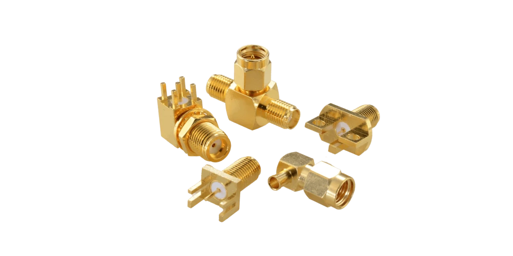
This image shows SMA male and female panel mount adapters with flange mounting structures. These RF connectors are designed for integration into electronic devices and provide a compact solution for signal routing, RF testing, antenna connections, and communication system applications.
RF equipment does not always use the same connector standard.
A test instrument purchased several years ago may use BNC. A newer RF module may provide an SMA interface. An antenna assembly may use an N-type connector because it needs stronger mechanical performance outdoors.
Replacing all equipment to achieve the same connector interface is usually unrealistic.
The adapter provides a practical transition.
The purpose is straightforward:
- Convert one connector interface to another
- Allow existing equipment to work together
- Reduce the need for multiple cable versions
- Support laboratory testing and product development
Common conversion combinations include:
| Adapter Combination | Typical Application |
| SMA to BNC adapter | RF instruments and laboratory equipment |
| SMA to N adapter | Antenna systems and communication equipment |
| SMA to TNC adapter | Outdoor and vibration environments |
| SMA to 2.92mm adapter | Microwave testing |
| SMA to 3.5mm adapter | Precision RF measurement |
However, the adapter name alone does not define the correct part.
For example, “SMA to BNC adapter” may refer to several different products:
- SMA male to BNC female
- SMA female to BNC male
- SMA right angle to BNC
- Panel mount SMA to BNC
These parts solve different connection problems.
A purchasing specification that only says:
SMA to BNC adapter
leaves too many questions unanswered.
Match the Adapter Interface Before Looking at the Product Listing
Many incorrect RF purchases happen because buyers start from a catalog instead of the actual connection requirement.
The correct selection process should begin with the equipment.
Three questions usually determine the adapter type:
Which connector is installed on the equipment?
A signal generator may have an SMA female port.
A spectrum analyzer may use another interface.
The adapter must match the equipment side first.
Which connector is available on the cable?
The cable assembly determines the opposite interface.
A wrong gender combination can create an unnecessary second adapter, adding another transition point.
What environment will the connection operate in?
A laboratory bench and an outdoor antenna system have different requirements.
A compact SMA adapter may be suitable for indoor testing.
An N-type transition may be preferred where mechanical strength and environmental exposure matter.
When Does an SMA to BNC Adapter Make Sense?
The SMA to BNC adapter is one of the most commonly used RF conversion products because BNC remains widely used in measurement equipment.
This connection is common during development because engineers often combine newer RF modules with existing laboratory equipment.
Typical applications include:
- Signal generators
- Oscilloscopes
- RF test instruments
- Development platforms
But there is an important detail.
BNC is not automatically the same as SMA electrically.
The adapter should still be checked for:
- Impedance
- Frequency range
- Application requirement
A 50Ω SMA adapter is normally used with 50Ω RF systems.
Using a connector combination only because it physically fits can create unexpected measurement results.
For example, a low-frequency test connection may work without noticeable issues, while a higher-frequency RF measurement may show increased reflection.
The difference is not visible from the outside.
It comes from the electrical transition inside the adapter.
Why Can a Correct-Looking SMA Adapter Still Create RF Problems?
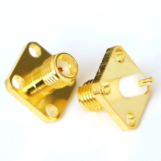
This image shows different types of SMA RF adapters, including SMA male adapters, SMA female adapters, straight adapters, and panel mount structures. These adapters are designed for RF connector conversion and provide reliable signal connections for wireless communication equipment, antenna systems, RF testing devices, and microwave applications.
An adapter is often the smallest component in an RF chain, but it sits directly in the signal path.
This creates a common misunderstanding during purchasing and testing.
Engineers may check:
- Connector thread size
- Mechanical fit
- Cable connection
Everything appears normal.
However, RF systems do not only depend on whether two parts can physically connect.
The electrical transition inside the adapter also matters.
Each transition can influence the signal.
Typical issues include:
- Higher VSWR
- Reduced return loss
- Additional insertion loss
- Measurement variation
This is why an SMA adapter should be considered as part of the RF system rather than as a simple mechanical accessory.
How Does Impedance Affect SMA Adapter Selection?
Impedance is one of the first specifications engineers should confirm.
Most SMA adapters used in RF applications are designed for 50Ω systems.
If one component introduces an impedance difference, part of the signal energy may reflect back toward the source.
The connector may physically fit, but the electrical characteristics may not match.
| System Type | Typical Application | Common Impedance |
| RF test equipment | VNA, spectrum analyzer, signal generator | 50Ω |
| Wireless communication | Antenna modules, RF devices | 50Ω |
| Video/broadcast systems | CATV, video equipment | 75Ω |
An adapter should not be selected only because both connectors share the same appearance.
The impedance of the entire RF path needs to be considered.
What Happens When SMA Adapters Affect VSWR and Return Loss?
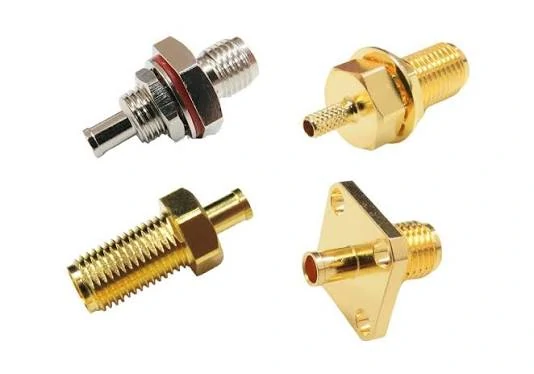
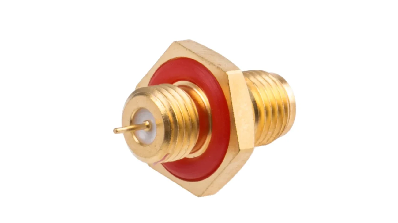
This SMA female panel mount RF adapter features a flange mounting design for secure installation on electronic equipment panels. The adapter provides a stable 50 ohm RF interface and is widely used in RF modules, communication systems, antenna applications, and laboratory testing equipment requiring reliable connector performance.
VSWR is one of the most commonly discussed parameters when evaluating RF adapters.
A simple continuity test only confirms that the electrical path exists.
It does not tell engineers whether the RF energy is transferring efficiently.
For example:
An SMA adapter may show perfect continuity.
The connector may tighten correctly.
The system may still show poor RF performance during VNA testing.
The reason is that continuity does not evaluate:
- Impedance matching
- Reflection characteristics
- Frequency response
VSWR
Voltage Standing Wave Ratio describes the relationship between transmitted and reflected energy.
Return Loss
Return loss describes how much signal is reflected back compared with the transmitted signal.
A better-matched connection generally provides higher return loss.
Insertion Loss
Insertion loss indicates how much signal power is reduced after passing through the adapter.
The effect depends on:
- Frequency
- Adapter design
- Interface precision
- Connection quality
For a simple laboratory connection, the impact may be acceptable.
For calibration equipment or microwave measurement systems, these parameters become much more important.
Why Does Frequency Range Matter More Than Many Buyers Expect?
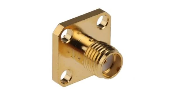
This image shows a precision SMA RF adapter with male and female connector interfaces. The 50 ohm SMA adapter adopts a gold plated metal body design to provide good electrical conductivity and corrosion resistance. It is suitable for RF testing systems, wireless communication equipment, antenna connections, and microwave applications.
A common mistake is assuming that all SMA adapters are equivalent because they share the same connector family.
They are not.
An SMA adapter designed for a lower-frequency application may use a different internal structure compared with a precision microwave version.
The differences may include:
- Contact geometry
- Insulator structure
- Machining tolerance
- Material selection
- Interface control
At higher frequencies, these details affect the signal path.
A buyer selecting an adapter should confirm:
- Maximum operating frequency
- Target application frequency
- Required VSWR
- Measurement requirements
For example:
A connection used for a general RF module may have different requirements from a VNA calibration setup.
Both may use SMA interfaces.
The selection criteria are not identical.
How Should Engineers Select Between SMA to 2.92mm and SMA to 3.5mm Adapters?
SMA to 2.92mm and SMA to 3.5mm adapters are both used in high-frequency applications, but they are not interchangeable by default.
The correct choice depends on the equipment and measurement requirement.
| Adapter Type | Typical Application | Selection Focus |
| SMA to 2.92mm | Microwave test transition | Frequency capability and interface compatibility |
| SMA to 3.5mm | Precision RF measurement | Repeatability and measurement stability |
| Standard SMA adapter | General RF conversion | Equipment compatibility |
A common purchasing mistake is selecting only by the highest frequency number shown on a specification sheet.
For example:
An adapter rated for a higher frequency does not automatically improve a complete RF system.
The final result still depends on:
- Cable performance
- Connector quality
- Test setup
- Calibration condition
The adapter rating is only one part of the complete system.
Does Adding Multiple Adapters Reduce RF Measurement Accuracy?
During engineering development, using several adapters together is normal.
This approach saves time during prototype testing.
However, each adapter introduces another interface.
The more interfaces added, the more variables appear.
Possible effects include:
- Additional insertion loss
- More reflection points
- Greater measurement uncertainty
- Reduced repeatability
This does not mean adapters should always be avoided.
The correct approach depends on the purpose.
Prototype stage
Flexibility is often more important.
Production stage
Repeatability becomes more important.
A fixed cable assembly may reduce unnecessary connection points.
Should You Choose an SMA Adapter or a Custom RF Cable Assembly?
Adapters and cable assemblies solve different engineering problems.
An adapter is mainly used for flexibility.
A cable assembly is usually selected for a fixed RF path.
| Application | Suitable Choice |
| Prototype testing | SMA adapter |
| Laboratory equipment conversion | SMA adapter |
| Temporary RF connection | SMA adapter |
| Production equipment | Custom cable assembly |
| Fixed antenna installation | Custom cable assembly |
| High-repeatability testing | Minimize adapter usage |
For example:
A research laboratory may frequently change between SMA, BNC, N, and microwave interfaces. Adapters are practical because the setup changes often.
A production line testing thousands of units may prefer a dedicated cable assembly because fewer connection points usually mean fewer variables.
The choice depends on the actual working environment.
What Should Be Checked Before Using an SMA Adapter?
Before installation, basic inspection should be completed.
Why Do SMA Adapter Orders Often Need More Technical Details?
A simple product name is rarely enough for RF components.
This is especially true for adapters because the same connector family can include many different versions.
A request such as:
“Need SMA adapter”
does not define the actual requirement.
Without this information, the supplier can only match the appearance.
That may work for a basic connection.
It may fail when the part is installed into an actual RF system.
A better RF specification describes the adapter as part of the application.
For example:
Simple request:
SMA to N adapter
Better request:
SMA male to N female adapter, 50Ω, DC–18GHz, straight type, used for antenna testing, requiring stable mechanical connection.
The second description gives enough information for proper evaluation.
What Should Be Included in an SMA Adapter BOM?
A BOM description should allow different teams to understand the same component.
Engineering, purchasing, quality inspection, and suppliers should not need to guess what the part means.
A practical SMA adapter BOM may include:
| Item | Example |
| Connector A | SMA male |
| Connector B | BNC female |
| Impedance | 50Ω |
| Frequency Range | DC–6GHz |
| Structure | Straight |
| Material | Brass / Stainless Steel |
| Plating | Gold / Nickel |
| Application | RF testing |
| Inspection | Visual + RF test if required |
This information helps avoid incorrect substitutions.
For example, two SMA adapters may both fit the same equipment port.
However, differences in:
- Internal structure
- Contact design
- Frequency capability
- Mechanical tolerance
may make one suitable and another unsuitable.
In RF purchasing, “fits the connector” and “works in the system” are not always the same thing.
Which SMA Adapter Selection Mistakes Cause Problems Later?
Most adapter problems are not discovered during purchasing.
They appear during installation, testing, or production.
Several mistakes occur repeatedly.
Selecting Only by Connector Name
“SMA to BNC” describes the interface conversion, but not the complete product.
The missing information may include:
- Gender
- Impedance
- Frequency
- Structure
A wrong gender combination can force the user to add another adapter.
This creates:
- More connection points
- More mechanical stress
- Additional RF transitions
Ignoring the Cable Behind the Adapter
An adapter is usually connected to a cable.
The cable affects the final RF performance.
Important cable information includes:
- Cable type
- Cable diameter
- Cable length
- Frequency range
For example, an SMA adapter connected to a short test cable and the same adapter connected to a long coaxial cable may produce different system results.
The adapter should be selected together with the complete assembly.
Using the Highest Frequency Rating as the Only Selection Rule
A higher frequency specification does not automatically mean a better solution.
A system operating at 2GHz does not necessarily require the same adapter as a 26GHz microwave measurement setup.
The selection should match the actual requirement.
A production fixture running thousands of cycles may benefit from a dedicated cable assembly.
The decision depends on how the RF path will be used.
FAQ
Does an SMA adapter add signal loss?
Yes, any additional RF interface may introduce some insertion loss.
The actual impact depends on:
- Adapter quality
- Frequency
- Interface condition
- Number of adapters used
For high-frequency measurement systems, the effect should be verified.
Are SMA and reverse polarity SMA adapters interchangeable?
No.
Standard SMA and reverse polarity SMA use different contact structures.
Although they may look similar externally, they are not designed for the same mating interface.
The connector type should always be confirmed before ordering.
The SMA adapter is connected correctly, but why does the VNA show a different result after installation?
This usually means the problem is not the mechanical connection.
An SMA adapter adds another RF interface between the equipment and the cable. Even when the connector is tightened correctly, the internal transition can affect the measurement result.
Before replacing the adapter, check the complete RF path:
- Adapter impedance
- Operating frequency
- Cable type and length
- Connector condition
- Calibration method
A continuity test only proves that the signal path is connected. It does not show whether the RF transition has acceptable VSWR or return loss.
I need an SMA to N adapter for an antenna project. What details should I provide?
For antenna applications, the adapter specification should match the whole connection, not only the two connector names.
A supplier usually needs to know:
- SMA side gender
- N side gender
- Cable type
- Working frequency
- Installation environment
For example, an SMA male to N female adapter used inside a test enclosure may have different requirements from one installed outdoors near an antenna.
Providing the application information helps avoid receiving a part that fits mechanically but does not match the RF system.
