
A microwave test setup can fail before the measurement even starts.
A common example is replacing a damaged test cable with another cable that appears compatible. The connector threads match, the interface looks correct, and the equipment can be physically connected. However, after adding an adapter between different connector standards, the measured VSWR changes, insertion loss increases, or calibration results become unstable.
This is where a 3.5mm adapter becomes more than a simple mechanical converter.
In high-frequency RF systems, the adapter sits directly inside the signal path. Its interface precision, impedance control, frequency rating, and mechanical alignment can influence the entire measurement chain. Engineers using VNAs, microwave modules, and test fixtures usually care less about whether two connectors can be screwed together and more about whether the transition remains electrically predictable.
How Does a 3.5mm Adapter Connect Different Microwave Interfaces?
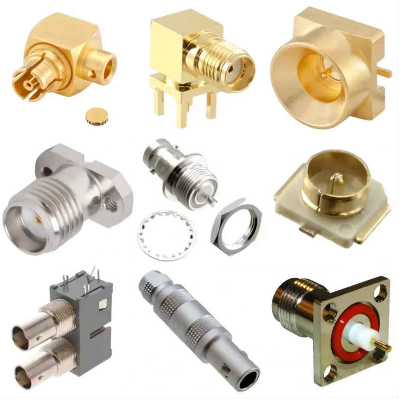
This image shows various precision RF connectors and adapters used in microwave measurement systems. A 3.5mm adapter serves as a transition component between different RF interfaces, allowing connection between VNAs, microwave modules, test fixtures, and high-frequency equipment while maintaining electrical consistency and mechanical accuracy.
The adapter becomes a transition point between two interfaces. At lower frequencies, this transition may appear simple. At microwave frequencies, small dimensional differences can affect the signal path.
A 3.5mm adapter is commonly used in:
- Vector network analyzer (VNA) testing
- Microwave calibration systems
- RF test fixtures
- High-frequency modules
- Precision measurement setups
- Laboratory development equipment
The purpose is not only to provide mechanical connection. The adapter must also maintain:
- 50Ω impedance
- stable contact geometry
- controlled reflection characteristics
- repeatable mating performance
A connector transition that works electrically at DC does not automatically perform well at microwave frequencies.
For example, a continuity test can confirm that the center conductor is connected, but it cannot confirm:
- return loss
- insertion loss
- phase stability
- VSWR performance
This is why microwave engineers normally evaluate adapters together with the complete RF path instead of judging only from connector appearance.
Why Are 3.5mm Adapters Used in Microwave Testing?
The 3.5mm connector family was developed for precision microwave applications where repeatable measurement results are required.
Compared with standard RF connectors used in general communication equipment, microwave test connectors usually require tighter mechanical tolerances.
The adapter structure must control several factors:
| Parameter | Why It Matters |
| Impedance | Prevents unwanted reflections in the RF path |
| Interface alignment | Maintains center conductor contact accuracy |
| Frequency rating | Determines usable microwave range |
| VSWR | Indicates reflection caused by mismatch |
| Insertion loss | Shows signal loss through the transition |
A small mismatch at the adapter interface can become more noticeable as frequency increases.
For example, an adapter used at several GHz may appear acceptable in a basic test. However, when the same adapter is used near the upper frequency limit of a microwave system, small mechanical variations may affect measurement repeatability.
This is why precision RF adapters are often selected based on verified specifications rather than only connector type.
How Does a 3.5mm Adapter Fit Into an RF Measurement Chain?
When engineers build a microwave test system, every additional connection introduces another potential transition point.
Each interface can contribute:
- reflection
- insertion loss
- mechanical uncertainty
A single adapter may have minimal impact when properly selected. Problems usually appear when multiple adapters are stacked together.
For temporary laboratory testing, adapters provide flexibility. Engineers can connect different generations of equipment without replacing expensive cable assemblies.
For production environments, however, a custom cable assembly may sometimes provide better repeatability because it reduces the number of connection points.
The choice depends on the application:
| Application | Preferred Solution |
| Laboratory testing | Adapter provides flexibility |
| Prototype development | Adapter reduces setup changes |
| Calibration work | Precision adapter with verified data |
| Production equipment | Custom cable assembly may reduce variation |
How Do You Choose Between SMA, 2.92mm, and 3.5mm Adapters?
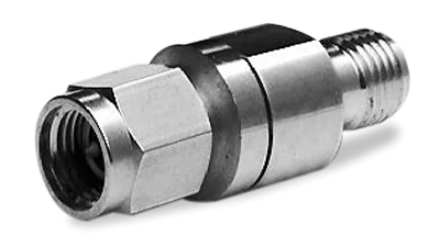
This image illustrates different RF adapter connector structures. When selecting a microwave adapter, engineers need to verify connector type, gender, frequency range, impedance, and application requirements instead of relying only on external appearance.
SMA, 2.92mm, and 3.5mm connectors look similar, which creates a common sourcing mistake.
How Should You Compare SMA and 3.5mm Adapters?
3.5mm connectors are more commonly associated with precision microwave measurement environments.
A simplified comparison:
| Item | SMA | 3.5mm |
| Typical Use | General RF applications | Microwave testing |
| Mechanical Precision | Standard RF tolerance | Higher precision interface |
| Common Equipment | RF modules, antennas | VNA, test fixtures |
| Application Focus | Communication systems | Measurement accuracy |
This does not mean SMA connectors cannot be used at higher frequencies.
The important point is that the connector name alone does not define the complete RF performance.
How Does Frequency Range Affect 3.5mm Adapter Selection?
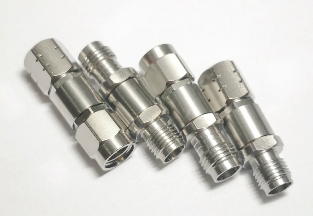
This precision 3.5mm RF adapter demonstrates the mechanical design required for microwave applications. High-quality machining, accurate interface alignment, and reliable contact performance help reduce signal reflection and improve measurement consistency in RF testing systems.
A 3.5mm adapter may look identical from the outside, but the usable frequency range can be very different between models.
This is a common mistake during RF sourcing.
A buyer checks the connector name, confirms the thread size, and assumes the adapter can be used in the same microwave system. The problem appears later when the measurement moves closer to the upper frequency limit.
For microwave applications, the connector interface is only one part of the specification.
Before selecting a 3.5mm adapter, engineers should confirm:
- frequency range
- VSWR specification
- insertion loss
- impedance
- interface accuracy
- application environment
A connector rated for DC–6 GHz should not automatically be used in a 26.5 GHz measurement system, even if the mechanical interface is compatible.
The RF path does not only depend on whether the parts can connect. It depends on whether the transition maintains acceptable electrical performance at the operating frequency.
How Can You Check the Frequency Margin of a Microwave Adapter?
The rated frequency of an adapter should have enough margin above the actual working frequency.
A simple selection reference:
Frequency Margin Ratio = Adapter Rated Frequency ÷ System Operating Frequency
Example:
A microwave test system operates at 18 GHz.
| Adapter Rating | Frequency Margin Ratio | Recommendation |
| 18 GHz | 1.0× | Minimum limit, verify carefully |
| 26.5 GHz | 1.47× | More suitable for general testing |
| 40 GHz | 2.22× | Better for sensitive measurement |
The higher the frequency, the more attention should be paid to margin.
This does not mean choosing the highest GHz specification in every case. A higher-frequency adapter may increase cost, while the system may not require that capability.
The correct approach is matching:
- operating frequency
- measurement accuracy
- budget
- expected future expansion
Why Do Microwave Adapters Require Tight Mechanical Tolerance?
At microwave frequencies, mechanical dimensions directly affect electrical behavior.
Small changes in:
- center contact position
- dielectric spacing
- connector face alignment
- machining tolerance
can influence RF performance.
A typical adapter contains several precision areas:
| Area | Potential Effect |
| Center conductor alignment | Reflection and contact stability |
| Interface surface | Repeatability during mating |
| Insulator structure | Impedance control |
| Thread machining | Mechanical alignment |
This is why precision microwave adapters are usually manufactured with tighter dimensional control than general-purpose RF adapters.
A part can pass basic electrical continuity testing and still create unexpected measurement variation.
Continuity confirms the circuit path.
It does not confirm microwave performance.
How Should You Select Male and Female 3.5mm Adapters?
Another frequent ordering problem is selecting the wrong connector gender.
Check:
- center pin type
- socket structure
- thread position
- equipment port direction
- cable connector gender
A simple mistake in gender selection can delay a test project because the adapter may arrive physically correct but impossible to install.
How Do You Match Adapter Gender With Equipment and Cable Assembly?
The correct selection should follow the complete RF connection chain.
For production systems, unnecessary adapter stacking should be avoided.
Every additional transition introduces another possible source of:
- reflection
- insertion loss
- mechanical wear
- assembly variation
When Should You Use an Adapter Instead of a Custom Cable Assembly?
The decision usually depends on how often the connection will be changed.
| Situation | Adapter | Custom Cable Assembly |
| Laboratory measurement | Suitable | Usually unnecessary |
| Prototype testing | Flexible choice | Possible after design freeze |
| Production equipment | Limited use | Usually preferred |
| Frequent connector changes | Convenient | Less flexible |
| Maximum repeatability | Depends on setup | Better control |
A custom cable assembly reduces the number of interfaces in the RF path.
The second approach removes one transition point.
The correct choice depends on whether flexibility or repeatability is more important.
How Do You Test a 3.5mm Adapter Before RF Deployment?
Visual inspection is the first step, but it is not enough for microwave applications.
Before installation, check:
- connector face condition
- center contact damage
- contamination
- thread condition
- mechanical deformation
A damaged interface may still connect mechanically but create unstable RF results.
3.5mm Adapter RF Acceptance Checklist
Before releasing a microwave adapter into a test system, engineers can record the following information:
| Parameter | Record |
| Adapter Type | SMA / 2.92mm / 3.5mm |
| Conversion Direction | Input → Output Interface |
| Gender | Male / Female |
| Frequency Range | GHz |
| Impedance | 50Ω |
| VSWR | Tested Value |
| Insertion Loss | dB |
| Connector Condition | Pass / Fail |
| Test Equipment | VNA Model |
| Final Result | Accept / Reject |
This checklist helps prevent a common mistake: accepting an adapter only because the connector can be installed.
For microwave systems, mechanical compatibility is only the first requirement. Electrical verification determines whether the adapter is suitable for the actual application.
When Should You Use a 3.5mm Adapter Instead of a Custom Cable?
In a laboratory environment, engineers often need to connect different instruments, calibration kits, and prototype modules. In this situation, flexibility is usually more valuable than minimizing every connection point.
A precision adapter allows different connector standards to work together without replacing the existing cable system.
Typical adapter applications include:
- connecting different generations of microwave equipment
- temporary RF validation setups
- prototype testing
- calibration configuration changes
- laboratory measurement systems
However, production equipment has different requirements.
When an RF connection is installed permanently, repeated assembly changes are usually undesirable. A dedicated cable assembly can reduce:
- connector transitions
- mechanical stress
- operator variation
- measurement uncertainty
How Do You Balance Flexibility and RF Repeatability?
The decision should be based on the actual working environment.
| Application Condition | Recommended Choice | Reason |
| Frequent equipment changes | 3.5mm adapter | Easy configuration adjustment |
| Prototype development | Adapter or adapter cable | Supports design changes |
| Calibration laboratory | Precision adapter | Maintains measurement flexibility |
| Mass production equipment | Custom cable assembly | Reduces connection variation |
| Long-term fixed installation | Custom cable assembly | Fewer transition points |
An adapter is not automatically better or worse than a cable assembly.
It solves a different engineering problem.
A laboratory engineer may prefer a 3.5mm adapter because the setup changes every day.
A production engineer may prefer a custom cable because the same connection must work thousands of times with consistent results.
How Do You Specify the Right 3.5mm Adapter for Ordering?
Many purchasing mistakes happen because the request sent to the supplier contains only the connector name.
For example:
“Need 3.5mm adapter.”
This description is not enough.
How Can Buyers Avoid Selecting a 3.5mm Adapter Only by Appearance?
SMA, 2.92mm, and 3.5mm connectors can appear very similar in product photos.
This creates a common procurement risk.
A connector photo cannot show:
- internal contact geometry
- dielectric structure
- machining accuracy
- actual frequency capability
Before approving a supplier sample, buyers should confirm:
| Check Item | Why It Matters |
| Connector standard | Prevents incorrect substitution |
| Frequency rating | Matches application requirements |
| Impedance | Maintains RF system design |
| Gender | Ensures mechanical connection |
| Test data | Confirms RF capability |
| Material/plating | Affects durability and contact stability |
For microwave components, the specification should always describe the complete requirement instead of only the external shape.
Why Are Precision RF Adapters Becoming More Important?
Higher-frequency RF development has increased demand for more controlled connection solutions.
As frequency increases, small changes become more visible.
A slightly damaged connector face, excessive adapter stacking, or inconsistent mating torque can affect measurement repeatability.
This is why engineers pay more attention to:
- calibration stability
- connector handling
- measurement consistency
- interface protection
A good RF adapter does not remove all system uncertainty, but it helps control one important part of the signal path.
FAQ
How do I choose between a SMA to 3.5mm adapter and a 2.92mm to 3.5mm adapter?
The choice depends on the connector interfaces already used in the RF system. A SMA to 3.5mm adapter is commonly used when connecting general RF equipment with microwave test equipment. A 2.92mm to 3.5mm adapter is more common in precision microwave environments where both interfaces are designed for higher-frequency testing. Before ordering, confirm the equipment port, connector gender, frequency requirement, and application purpose.
What information should be provided when ordering a 3.5mm adapter?
A connector name alone is usually not enough for RF sourcing. A better specification includes the interface conversion direction, male or female configuration, impedance, frequency requirement, and application.
Why can the RF result change after installing a 3.5mm adapter?
The change usually comes from the additional transition point. At microwave frequencies, the contact position, interface alignment, and impedance matching inside the adapter can affect the measurement result. A cable may pass a continuity check before installation, but the final RF performance still needs to be checked through parameters such as VSWR, insertion loss, or VNA measurement.
Why does a 3.5mm adapter need more attention than a normal RF connector?
A 3.5mm adapter is not only a mechanical connection part. In a microwave test setup, it becomes another section of the signal path. The contact condition, interface machining, and connection method can affect the measurement result. This is why engineers usually check the adapter together with the cable, test equipment, and operating frequency instead of looking only at the connector shape.
Can a 3.5mm adapter be selected only by checking the connector size?
This is a common mistake during RF component sourcing. Several microwave connectors have a similar appearance, but their mechanical details and electrical characteristics are not identical. These details help avoid ordering a part that fits physically but does not match the system.
Final Buying Guidance for 3.5mm Adapters
A 3.5mm adapter should not be selected only because the connector fits.
For microwave applications, the important details are:
- correct interface conversion
- proper gender selection
- sufficient frequency margin
- controlled impedance
- acceptable VSWR
- verified insertion loss
- suitable mechanical design
Before placing an order, provide the supplier with the actual application information:
- equipment model or interface
- operating frequency
- cable type
- required conversion direction
- testing requirement
This allows the adapter to be evaluated as part of the RF system rather than as an isolated component.
A properly specified 3.5mm adapter can simplify microwave testing, reduce unnecessary cable replacement, and provide a practical connection solution between different RF interfaces.
