
A commonRF test failure does not always come from a bad cable or a damaged connector.
Sometimes the signal entering the next device is simply too strong.
A spectrum analyzer may show an unexpected trace. A receiver front end may become unstable. A power amplifier may stop behaving linearly during testing.
The first reaction is often to check the equipment settings or replace the cable assembly.
But in many RF systems, the issue is signal level control.
An RF attenuator is often added between two RF stages to reduce the signal by a known amount. The purpose is not only to make the signal weaker. The component also needs to maintain the expected impedance environment so the RF path remains predictable.
This is where many purchasing mistakes happen.
A request such as “10 dB SMA attenuator” is usually not enough information for a correct selection.
The supplier still needs to confirm:
- Is the system 50 ohm?
- What frequency range is required?
- What power level will pass through the attenuator?
- Is this for laboratory testing or continuous operation?
- Is the connector SMA male, SMA female, or another interface?
The dB value defines the attenuation.
It does not define whether the attenuator is suitable for the application.
How Does an RF Attenuator Control Signal Power Without Changing the System?
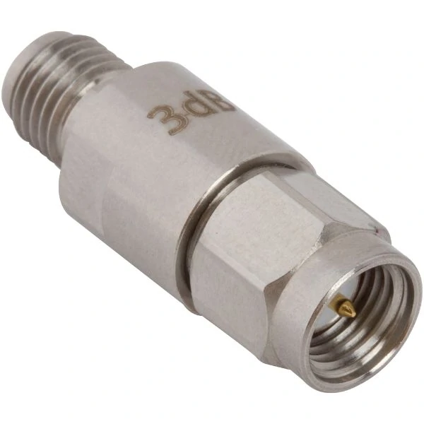
This close-up image shows a 3dB SMA RF attenuator, suitable for applications where engineers need predictable signal reduction without changing the RF system interface.
An RF attenuator is a passive component that introduces a controlled amount of signal loss into an RF transmission path.
The word “controlled” is the key point.
In a real RF system, engineers are rarely trying to reduce a signal randomly. They normally need a predictable change:
- reduce a transmitter output before measurement;
- protect a sensitive receiver input;
- adjust signal level during calibration;
- prevent an amplifier from entering compression.
A fixed attenuator, for example, does not require any adjustment after installation. A 10 dB attenuator continues to provide approximately the same reduction every time it is used within its specified frequency and power range.
That repeatability is valuable in production testing.
A technician can replace one test fixture with another and keep the same RF loss condition without manually changing instrument settings.
Why do engineers add attenuation before sensitive RF equipment?
RF devices usually have an acceptable input range.
Exceeding that range may create problems that are not immediately obvious.
A receiver may still produce an output signal, but internal stages may already be operating incorrectly.
A spectrum analyzer may display a waveform, but the measurement result may include compression effects.
An amplifier may still amplify, but the gain characteristics may no longer match the expected specification.
Adding an attenuator creates additional control between RF stages.
Typical applications include:
| Application Situation | Reason for Using an Attenuator |
| High signal from RF source | Reduce input level |
| Receiver testing | Protect front-end circuits |
| Amplifier evaluation | Control drive power |
| Calibration setup | Create repeatable loss |
| RF measurement | Keep instruments within range |
For example, a signal generator outputs +13 dBm, but the device under test requires approximately +3 dBm input.
A 10 dB attenuator provides the required reduction without changing the signal generator settings.
Keep 50 ohm impedance while reducing signal level
An attenuator is not simply a resistor placed in series with a cable.
RF systems are sensitive to impedance changes.
Most RF measurement systems, antennas, and coaxial assemblies use a 50 ohm transmission environment.
A properly designed 50 ohm attenuator reduces signal power while maintaining a controlled RF path.
If the impedance is incorrect, part of the signal can reflect back toward the source.
This may affect:
- measurement accuracy;
- VSWR;
- insertion loss;
- system stability.
For low-frequency applications, a small mismatch may not create obvious problems.
At higher frequencies, the same mismatch can become measurable.
This is why an attenuator specification should always include impedance, frequency range, and connector interface together.
How is an RF attenuator different from a load, terminator, or amplifier?
RF components are sometimes confused because they may use similar coaxial interfaces.
However, their functions are different.
| Component | Main Purpose | Signal Behavior |
| RF Attenuator | Reduce signal level | Signal continues with lower power |
| Dummy Load | Absorb RF power | Signal energy is converted to heat |
| RF Terminator | End unused RF port | Prevent open-port reflection |
| Amplifier | Increase signal level | Signal power increases |
A common mistake is replacing an attenuator with a dummy load.
The two components solve different problems.
If a test engineer needs a reduced signal at the output, a dummy load will not work because it removes the signal path instead of passing a lower-level signal.
Similarly, an attenuator cannot replace a termination component on an unused port because it does not simply “close” the RF path.
Do not select an attenuator only by the dB value
This is one of the most common specification gaps in RF purchasing.
A buyer may request:
“Need SMA 20 dB attenuator.”
But the supplier still cannot confirm the correct part.
The missing information may completely change the product selection.
A 20 dB SMA attenuator for a bench measurement system may be rated for low power.
A 20 dB coaxial attenuator for communication equipment may require a larger body and higher thermal capability.
Before selecting the part, confirm:
- attenuation value;
- frequency range;
- power rating;
- impedance;
- connector type;
- operating environment.
The correct attenuator is the one that fits the entire RF path, not simply the one with the correct number printed on the label.
Which RF Attenuator Type Fits Your Application?
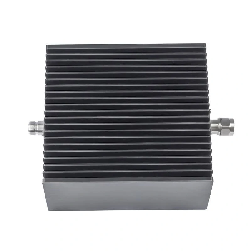
This image shows a high power coaxial RF attenuator with a finned heat sink body, suitable for RF systems that require stable attenuation, power margin, and thermal management.
A request for an RF attenuator usually starts with one number.
“Need 10 dB.”
The problem is that the same attenuation value can appear in very different products.
A test engineer may need a small SMA fixed attenuator for a calibration setup.
A communication equipment manufacturer may need a higher-power coaxial attenuator installed near an RF output stage.
A research laboratory may need a variable attenuator because the signal level changes during each measurement.
The attenuation value tells you how much signal is reduced.
The structure tells you how the component should be used.
When is a fixed RF attenuator the better choice?
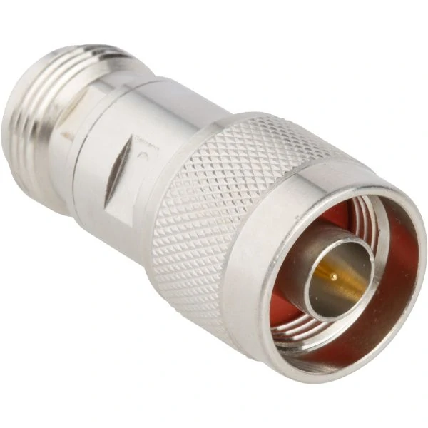
This image shows an N type RF attenuator used in coaxial RF systems where connector strength, impedance matching, frequency range, and power rating are important selection factors.
A fixed attenuator is usually the first option when the RF path has already been defined.
The signal level is known.
The required loss is known.
The test procedure does not require frequent adjustment.
This is why fixed attenuators are common in:
- RF test fixtures;
- communication equipment;
- calibration chains;
- receiver protection circuits;
- production inspection systems.
For example, a production line may test the same wireless module thousands of times.
The operator does not need to adjust attenuation manually for every unit.
A fixed attenuator provides a consistent condition.
That consistency matters more than flexibility in many manufacturing environments.
A common specification might look like:
SMA fixed attenuator, 50 ohm, 10 dB, DC–6 GHz, 2 W.
Although the description is short, every parameter has a purpose.
- SMA defines the interface.
- 50 ohm defines the RF environment.
- 10 dB defines signal reduction.
- DC–6 GHz defines the operating range.
- 2 W defines the power limit.
Missing any one of these details can lead to a wrong selection.
When should you use a variable RF attenuator?
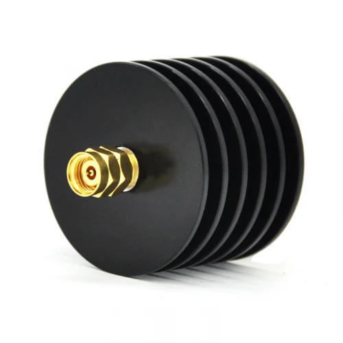
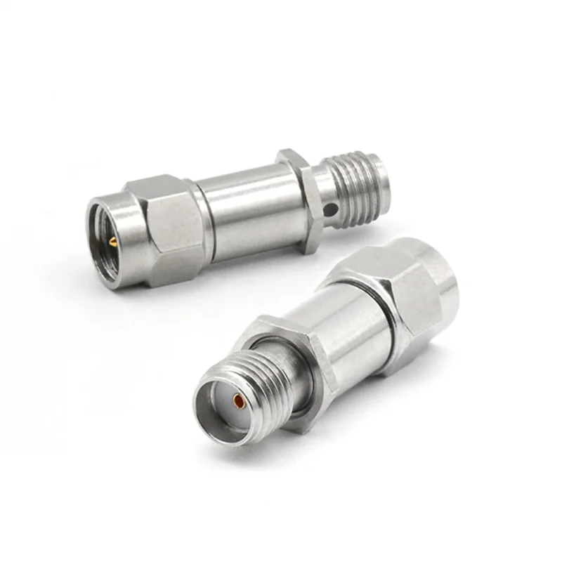
This image shows a heat sink style RF attenuator with an SMA interface, commonly used when attenuation, power handling, and thermal performance must be considered together.
Variable attenuators are normally used when engineers need to adjust signal levels during development or testing.
A typical situation:
A receiver design is being evaluated.
The engineer wants to know how the receiver behaves at different input levels.
Instead of replacing multiple fixed attenuators, a variable attenuator can change the signal level during the test.
Common applications include:
- receiver sensitivity testing;
- RF circuit adjustment;
- laboratory experiments;
- calibration work.
However, variable does not automatically mean better.
For a production environment where the same attenuation value is used every day, a fixed attenuator is often preferred.
Why?
Because fewer adjustment points mean fewer opportunities for variation.
The choice depends on the workflow.
Development usually values flexibility.
Production usually values repeatability.
Why are RF step attenuators common in measurement systems?
A step attenuator sits between fixed and continuously variable designs.
Instead of changing attenuation smoothly, it provides defined steps.
A typical unit may offer:
| Step Setting | Attenuation |
| Position 1 | 0 dB |
| Position 2 | 5 dB |
| Position 3 | 10 dB |
| Position 4 | 20 dB |
| Position 5 | 30 dB |
This approach is useful when test procedures require repeatable changes.
For example:
A receiver test procedure may require measurements at:
- 0 dB loss;
- 10 dB loss;
- 20 dB loss.
A step attenuator makes the process easier to document.
The test result can be linked to a specific attenuation position instead of a manual adjustment.
This is valuable in production environments where multiple operators may perform the same test.
Where do digital RF attenuators fit?
Digital attenuators are used when attenuation needs to be controlled electronically.
They are often found in:
- automated test equipment;
- communication systems;
- phased array systems;
- RF simulation platforms.
The main difference is control method.
A mechanical attenuator requires physical adjustment.
A digital attenuator receives control signals from the system.
This makes automation easier.
However, engineers should check more than the control method.
Important parameters still include:
- attenuation range;
- frequency range;
- switching speed;
- power handling;
- insertion loss.
A digitally controlled attenuator with unsuitable RF specifications will not improve the system.
How Should You Select an RF Attenuator by Power Rating?
The power rating is where many incorrect selections happen.
A 10 dB attenuator does not tell you whether it can handle:
- 100 mW;
- 2 W;
- 50 W.
The attenuation value and power capability are independent specifications.
A low-power SMA attenuator and a high-power coaxial attenuator may both provide 10 dB loss, but their internal construction is completely different.
Calculate actual RF power before selecting the attenuator
RF power may appear in different formats depending on the equipment.
Common units:
- dBm;
- mW;
- W.
The conversion formula is:
P(W)=10(dBm−30)/10
Some useful references:
| Signal Level | Power |
| 0 dBm | 1 mW |
| 10 dBm | 10 mW |
| 20 dBm | 100 mW |
| 30 dBm | 1 W |
| 40 dBm | 10 W |
When checking power rating, do not look only at the transmitter output.
The actual condition depends on:
- continuous operation time;
- pulse width;
- duty cycle;
- cooling condition.
A device used for a few seconds during laboratory testing may have completely different requirements from a component installed in a communication system running continuously.
Why should you leave power margin?
Running an attenuator exactly at its maximum rating is rarely a good design choice.
RF power becomes heat.
The higher the power, the more important thermal management becomes.
The actual temperature can change depending on:
- enclosure design;
- airflow;
- mounting position;
- ambient temperature.
For example, a 2 W SMA attenuator may be acceptable in a short measurement.
The same part may not be suitable if it is installed inside a sealed enclosure and operated continuously.
A practical specification usually includes some reserve.
The required margin depends on the application.
There is no universal number because the environment changes.
Match the attenuator connector with the RF system
Connector selection affects both mechanical installation and RF performance.
Common interfaces include:
| Connector | Typical Application | Selection Consideration |
| SMA | RF modules and laboratory testing | Compact size, common interface |
| N Type | Communication and higher power systems | Larger structure, stronger connection |
| BNC | General laboratory equipment | Convenient connection method |
| 2.92 mm / 3.5 mm | Microwave measurement | Higher frequency applications |
A frequent purchasing mistake is choosing an attenuator first and trying to solve the connector problem later.
This often leads to unnecessary adapters.
Every additional adapter introduces another connection point.
At lower frequencies, this may not create a noticeable issue.
At microwave frequencies, the effect can become part of the measurement uncertainty.
RF Attenuator Selection Worksheet
Before confirming an RF attenuator order, collect these parameters:
| Parameter | Example |
| Attenuation | 10 dB |
| Frequency Range | DC–6 GHz |
| Impedance | 50Ω |
| Power Rating | 2 W |
| Connector | SMA Female |
| Application | RF Testing |
| Operation Mode | Continuous / Pulse |
A complete request should look like:
10 dB SMA female fixed attenuator, 50Ω, DC–6 GHz, 2 W, used for RF test equipment.
This type of specification reduces unnecessary communication between buyer and supplier.
It also prevents a common problem:
The component arrives, the connector fits, the signal passes — but the RF performance is not what the system requires.
How Does Frequency Range Affect RF Attenuator Selection?
The attenuation value printed on an RF attenuator does not tell the complete story.
A 10 dB attenuator rated for 1 GHz and a 10 dB attenuator rated for 18 GHz may look similar from the outside.
The difference appears when the signal frequency increases.
At higher frequencies, the physical structure inside the component becomes part of the RF circuit.
Small changes in:
- resistor layout;
- internal connection length;
- connector transition;
- mechanical dimensions;
can affect the actual RF behavior.
This is why microwave attenuator selection requires more attention than simply checking the dB value.
Why does the same attenuation value behave differently at higher frequencies?
An RF attenuator converts part of the signal energy into heat through a resistive network.
At lower frequencies, the resistor network behaves close to the expected model.
As frequency increases, additional effects appear.
The component starts showing characteristics caused by:
- parasitic capacitance;
- parasitic inductance;
- internal transmission path;
- connector structure.
These effects can influence:
- attenuation flatness;
- VSWR;
- insertion loss;
- measurement accuracy.
For a general RF communication application, small variation may be acceptable.
For microwave measurement, the same variation may affect calibration results.
This difference explains why two products with the same attenuation value may have very different price levels.
The higher-cost option is not simply charging for a higher GHz number.
The internal design requirements are different.
Compare broadband and microwave attenuators before ordering
A common mistake is selecting an attenuator only because the frequency range appears to cover the application.
For example:
The system operates at 5 GHz.
An attenuator rated DC–6 GHz appears acceptable.
But if the system requires accurate measurement near the upper frequency limit, additional margin may be useful.
A practical comparison:
| Attenuator Category | Typical Use | Selection Focus |
| Broadband RF Attenuator | General RF systems | Stable attenuation across wide range |
| Microwave Attenuator | High-frequency measurement | Accuracy, VSWR, frequency margin |
For production equipment, the operating frequency may be fixed for years.
For laboratory equipment, engineers often need better margin because measurement conditions change.
Do not ignore attenuation accuracy across the operating band
A datasheet may specify:
10 dB attenuator
But the actual attenuation may vary slightly depending on frequency.
For example, a component may measure close to 10 dB at one frequency and show a different value near the upper limit.
Important specifications include:
- attenuation tolerance;
- VSWR;
- insertion loss flatness;
- return loss.
This matters especially when the attenuator is used as part of a calibration chain.
A small error repeated through several components can affect the final measurement result.
How Can Connector Interfaces Change RF Attenuator Selection?
The connector is not only a mechanical attachment point.
It is part of the RF path.
An attenuator with the correct electrical specifications may still be unsuitable if the interface does not match the equipment.
Common connector choices include:
- SMA;
- N Type;
- BNC;
- 2.92 mm;
- 3.5 mm.
Each interface has different application areas.
Match SMA, N-type, BNC, and coaxial attenuators to the system
| Connector | Common Application | Practical Consideration |
| SMA | RF modules, test cables, laboratory equipment | Compact and widely available |
| N Type | Communication systems and higher power applications | Larger structure and stronger connection |
| BNC | General test equipment | Quick connection method |
| 2.92 mm / 3.5 mm | Microwave measurement | Higher-frequency applications |
SMA attenuators are frequently used in laboratory environments because many RF instruments and cable assemblies use SMA interfaces.
N-type attenuators are often selected where mechanical strength and power capability are more important.
Microwave connectors such as 2.92 mm and 3.5 mm are commonly used when measurement frequency becomes the main concern.
The connector choice should follow the system requirement.
Not the other way around.
Check SMA gender and polarity before placing an order
“SMA attenuator” is still not a complete specification.
The supplier needs to know:
- SMA male or SMA female;
- connector orientation;
- polarity requirement;
- mating equipment interface.
A common issue occurs when engineers assume similar-looking connectors can replace each other.
Standard SMA and reverse polarity SMA are different.
They may appear close visually, but the internal contact structure is not the same.
For prototype testing, this mistake wastes time.
For production, it can create assembly problems across an entire batch.
Avoid unnecessary adapters in precision RF paths
Adapters are useful when different interfaces must be connected.
However, every additional connection introduces another variable.
Possible effects include:
- additional insertion loss;
- impedance discontinuity;
- mechanical tolerance;
- increased connection points.
For general laboratory work, an adapter may be acceptable.
For precision microwave testing, reducing unnecessary interfaces is usually preferred.
A shorter RF path with fewer transitions is easier to verify.
How Can You Test RF Attenuator Performance?
A specification sheet describes expected performance.
A measurement confirms actual performance.
For incoming inspection or qualification testing, engineers normally verify:
- attenuation value;
- frequency response;
- VSWR;
- return loss;
- connector condition.
The testing method depends on the application.
A simple power measurement may be enough for a general RF assembly.
A VNA measurement may be required for microwave applications.
RF Attenuator Test Record
For supplier quality control or incoming inspection, record the actual test condition.
| Test Item | Record Example |
| Model | Product number |
| Frequency | Test frequency |
| Rated Attenuation | Datasheet value |
| Measured Attenuation | Actual result |
| Input Power | Applied power |
| VSWR | Measurement result |
| Connector | SMA / N / Other |
| Test Equipment | Instrument model |
| Result | Pass / Fail |
This type of record is useful when:
- repeated orders are placed;
- customers compare different batches;
- troubleshooting is required.
A measurement history often provides more value than checking only whether the product physically matches the drawing.
How Do You Specify the Correct RF Attenuator for a Project?
Many RF sourcing problems start with incomplete specifications.
A request like:
“Need 100 pcs SMA 10 dB attenuator.”
does not define enough information.
A complete requirement should include:
- attenuation;
- frequency range;
- impedance;
- power rating;
- connector type;
- application;
- testing requirement.
FAQ
Is a higher-power attenuator always better?
Not necessarily.
A higher-power model may increase size and cost.
The correct choice depends on actual operating conditions.
A laboratory signal path and a transmitter output path require different designs.
Why does attenuation change at higher frequencies?
Higher frequencies are affected by:
- internal structure;
- parasitic effects;
- connector transition;
- bandwidth limitations.
This is why frequency range and attenuation accuracy should be evaluated together.
Why is a 10 dB RF attenuator not always the same from one supplier to another?
Because the 10 dB value only describes signal reduction. It does not tell you the frequency range, power rating, connector quality, attenuation accuracy, or VSWR. A small SMA attenuator for bench testing and a larger coaxial attenuator for higher-power equipment may both be marked 10 dB, but they are built for different working conditions. Always check the full RF path before treating them as interchangeable.
Can I use a low-power SMA attenuator for a short test?
Sometimes yes, but only when the input power and test duration are clearly within the rating. Short bench tests are less demanding than continuous operation inside equipment. The risk comes when a part that worked for a few seconds in the lab is later installed in a system that runs for hours. RF power becomes heat, so power margin and ventilation still matter.
What should I write when ordering an RF attenuator?
Do not only write “SMA 10 dB attenuator.” A better request is: 10 dB SMA fixed attenuator, 50Ω, DC–6 GHz, 2 W, used for RF test equipment. If accuracy is important, also add attenuation tolerance, VSWR requirement, connector gender, and whether the application is continuous or pulse operation. This gives the supplier enough information to check the correct part.
Final Practical Note
The correct RF attenuator is not selected by attenuation value alone.
A reliable specification combines:
- signal reduction requirement;
- frequency range;
- impedance;
- power capability;
- connector interface;
- measurement expectation.
A small RF attenuator used in a laboratory test cable and a high-power attenuator installed in communication equipment may share the same dB value, but they solve different engineering problems.
Before ordering, define the RF environment first.
A clear specification prevents the most common mistake in RF sourcing:
the component connects mechanically, but it does not perform correctly in the system.
