
How Does a Dummy Load Help an RF System Absorb Signal Power?
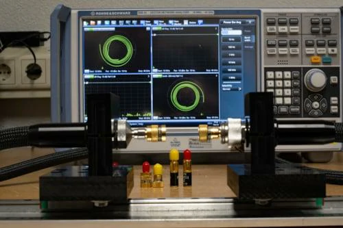
This image shows an RF test bench using a vector network analyzer to evaluate dummy load performance, including S11, VSWR, return loss, and impedance matching conditions.
A transmitter can work normally on the bench and still fail during testing if its output port is left open or connected to an unsuitable load.
This is a common mistake during RF development. Engineers may disconnect an antenna, replace a module, or temporarily leave a coaxial port unused while debugging. At low frequencies, the problem may not be obvious. At RF and microwave frequencies, the same action can create significant reflected energy that travels back toward the source.
A dummy load provides a controlled 50-ohm termination that absorbs RF power instead of reflecting it back into the system. It allows engineers to test transmitters, amplifiers, RF modules, and communication equipment under a known load condition without radiating a signal.
The basic purpose is simple:
The RF source generates energy. The dummy load receives that energy and converts it into heat.
However, selecting a suitable dummy load requires more than checking whether the connector fits. Impedance, frequency range, power rating, connector interface, cooling condition, and measurement requirements all affect whether the load will work correctly.
A 50-ohm dummy load rated for DC–6 GHz and 1 W may be suitable for laboratory signal testing, but it is not automatically suitable for a high-power transmitter output. Likewise, a high-power load with the correct wattage may still introduce unwanted mismatch if its frequency range does not cover the operating band.
This is why RF engineers normally evaluate dummy loads as part of the complete RF path rather than as an isolated component.
Understand why RF engineers use a dummy load instead of an open port
An open RF port does not simply mean “nothing is connected.”
At RF frequencies, an open circuit creates an impedance discontinuity. The incoming signal cannot be absorbed, so a large portion of the energy reflects back toward the source. The reflected wave can affect measurement accuracy and may stress sensitive RF components.
A dummy load solves this problem by presenting a controlled impedance, typically 50 ohms, to the RF system.
A properly selected RF dummy load helps provide:
| Situation | Without Dummy Load | With Dummy Load |
| Transmitter testing | RF energy reflects from open port | Output power is safely absorbed |
| Amplifier validation | Possible unstable operation | Controlled load condition |
| RF module measurement | Unpredictable reflection | Repeatable test environment |
| Production inspection | Different results between samples | Consistent verification |
For engineers, repeatability is often the main reason to use a dummy load. A test result is only meaningful when the RF system sees the same electrical condition every time.
For example, when checking an RF amplifier, connecting the output to an antenna introduces many variables:
- antenna impedance variation
- installation environment
- cable routing changes
- surrounding objects
- frequency-dependent mismatch
A dummy load removes most of these variables and allows the engineer to focus on the amplifier itself.
This is why dummy loads are widely used in:
- transmitter output testing
- power amplifier validation
- RF module verification
- antenna system development
- VNA calibration environments
- communication equipment production testing
A dummy load is not intended to replace an antenna in normal operation. It creates a controlled non-radiating condition for measurement and debugging.
Separate a dummy load from a terminator, attenuator, and resistor
Dummy loads are sometimes confused with other RF components because they may share similar physical structures.
A small coaxial dummy load may look similar to an RF terminator. Both may use a 50-ohm resistor element inside a connector body. The difference is mainly the application requirement.
| Component | Main Function | Typical Application |
| Dummy Load | Absorb RF power during testing | Transmitter and amplifier testing |
| RF Terminator | End an unused RF port | Prevent reflection from open ports |
| Attenuator | Reduce signal power by a known value | Signal level adjustment |
| Resistor | Provide electrical resistance | General circuit design |
A dummy load resistor is not simply a normal 50-ohm resistor placed inside a connector.
At RF frequencies, the physical construction becomes part of the electrical design. Lead length, parasitic capacitance, inductance, connector transition, and mechanical tolerances can change the impedance behavior.
A resistor that measures exactly 50 ohms with a multimeter may not behave as a 50-ohm RF load at several GHz.
This is a frequent sourcing misunderstanding:
DC resistance measurement confirms continuity, but it does not confirm RF performance.
For RF applications, engineers usually care about:
- operating frequency range
- return loss
- VSWR
- power handling capability
- connector quality
- thermal behavior
A coaxial dummy load designed for microwave testing requires controlled geometry, not only a resistance value.
How Do You Match a Dummy Load to a 50 Ohm RF System?
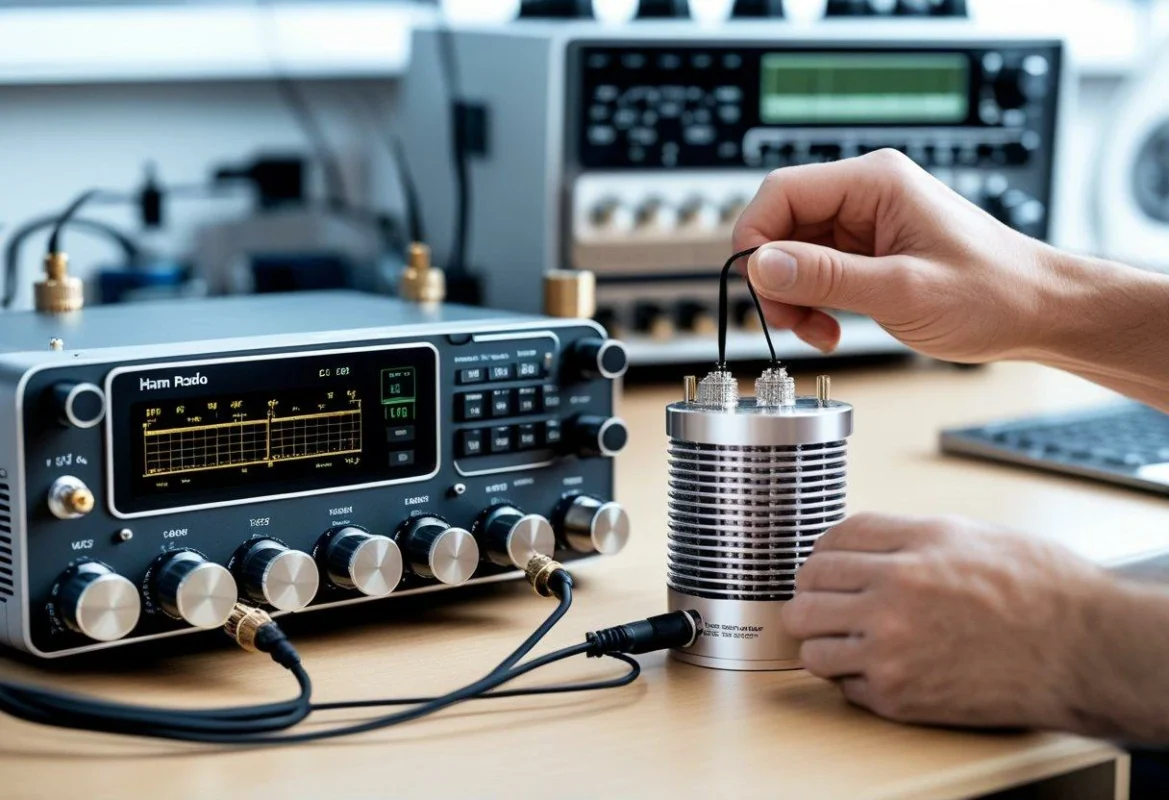
A dummy load can have the correct connector and still be the wrong component for an RF system.
This usually happens when the buyer only checks the interface type. For example, a load with an SMA connector may physically connect to an SMA cable, but the actual RF requirement may also include impedance, frequency range, power level, and measurement accuracy.
A complete RF path normally includes:
- RF source
- coaxial cable
- adapters or transitions
- connectors
- antenna or load
Every section affects the final impedance seen by the transmitter.
A mismatch in any part of the chain can increase reflected power and reduce measurement reliability. This is why professional RF testing systems normally specify the dummy load together with the complete signal path.
Verify impedance before connecting the load
Most RF test systems use a 50-ohm impedance environment.
A 50 ohm dummy load is designed to imitate the electrical behavior of a matched RF termination while safely absorbing power.
A typical specification may look like:
50Ω coaxial dummy load, DC–6 GHz, SMA male connector, 2 W continuous power rating.
Each parameter provides different information:
| Specification | Why It Matters |
| Impedance | Determines RF matching condition |
| Frequency Range | Defines usable operating band |
| Power Rating | Determines maximum heat handling |
| Connector Type | Determines mechanical compatibility |
| VSWR | Indicates reflection level |
A common mistake is selecting a dummy load only by wattage.
For example:
A 20 W load rated only to 1 GHz may not be suitable for a 5.8 GHz RF system. The power capacity looks sufficient, but the internal structure may no longer provide good impedance matching at the higher frequency.
Understand why a 50 ohm dummy load is the common RF standard
The 50-ohm standard is widely used because it provides a practical balance between power handling capability and transmission characteristics.
In engineering applications, 50Ω systems are common because they support:
- relatively high RF power transmission
- manageable conductor dimensions
- low-loss coaxial cable designs
- broad compatibility between equipment
This standard appears across many RF environments:
- communication equipment
- microwave testing
- antenna measurement
- wireless development
- laboratory instrumentation
However, impedance alone does not define the complete RF performance.
Two dummy loads can both be marked “50Ω” and still behave differently because of:
- resistor technology
- connector transition design
- internal matching structure
- frequency range
- manufacturing tolerance
At higher frequencies, mechanical details become electrical details.
A small change in connector geometry or internal connection length can affect return loss.
Avoid confusing DC resistance with RF impedance
One of the easiest mistakes during inspection is measuring a dummy load with a multimeter and assuming the result represents RF performance.
A technician may measure:
DC resistance: 49.8Ω
and conclude:
“The load is a perfect 50-ohm device.”
That conclusion is incomplete.
A multimeter only measures resistance under DC conditions. RF impedance changes with frequency because of parasitic effects.
At GHz frequencies, factors such as:
- unwanted inductance
- parasitic capacitance
- connector structure
- resistor package size
- internal assembly method
can affect the actual impedance.
The difference becomes more obvious as frequency increases.
For low-frequency applications, a simple resistance check may provide useful confirmation. For microwave applications, engineers normally verify performance with RF measurement equipment such as a VNA.
A proper RF dummy load evaluation may include:
- S11 measurement
- VSWR measurement
- return loss measurement
- frequency sweep testing
This distinction is especially important when purchasing loads for:
- VNA calibration
- microwave modules
- high-frequency amplifiers
- precision RF testing
How Should You Calculate Dummy Load Power Requirements?
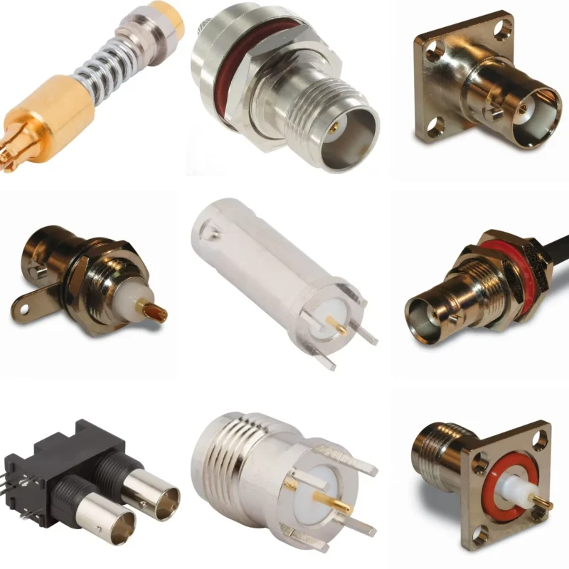
Power rating is usually the first specification buyers check, but it is also one of the easiest areas to misunderstand.
A dummy load rated at 10 W does not always mean it can safely absorb any 10 W RF signal under all conditions.
The actual requirement depends on:
- output power
- signal type
- duty cycle
- cooling condition
- ambient temperature
- operating frequency
A load used for continuous-wave laboratory testing experiences different thermal stress compared with a pulsed radar application.
Convert RF source power into actual load requirements
RF power may be expressed in:
- watts (W)
- milliwatts (mW)
- dBm
Common conversions:
| RF Power | Equivalent Wattage |
| 0 dBm | 1 mW |
| 10 dBm | 10 mW |
| 20 dBm | 100 mW |
| 30 dBm | 1 W |
| 40 dBm | 10 W |
| 50 dBm | 100 W |
This conversion helps engineers avoid selecting a load based only on equipment labels.
For example:
A transmitter specification may state:
- Output power: 37 dBm
A 5 W dummy load may appear sufficient, but operating exactly at the limit leaves no thermal margin.
A safer selection may require a higher rated load depending on cooling and test duration.
Consider continuous power, peak power, and duty cycle separately
RF systems do not always transmit continuously.
The three common operating conditions are:
CW Power
Continuous wave means the RF signal remains active continuously.
Example:
A laboratory amplifier outputting 5 W continuously.
The dummy load must handle the full power as heat.
Pulse Power
Pulse systems generate short bursts of high peak power.
Example:
A radar transmitter may produce high instantaneous power but only for a small percentage of time.
The peak value may be high, but thermal stress depends on the average energy.
Average Power
For pulsed systems:
Pavg=Ppeak×Duty Cycle
Example:
A 100 W pulse signal with a 10% duty cycle:
100W×0.1=10W
The average thermal load is 10 W.
However, the peak pulse capability of the dummy load still needs to be considered.
Dummy Load Power Selection Calculator
Before ordering a dummy load, engineers can use the following calculation sheet to estimate the required rating.
| Input Parameter | Description |
| Source Power | dBm or W |
| Frequency | MHz / GHz |
| Signal Type | CW / Pulse |
| Duty Cycle | % |
| Load Impedance | Ω |
| Cooling Condition | Natural / Forced Air |
| Required Safety Margin | % |
How Does Frequency Range Change Dummy Load Selection?
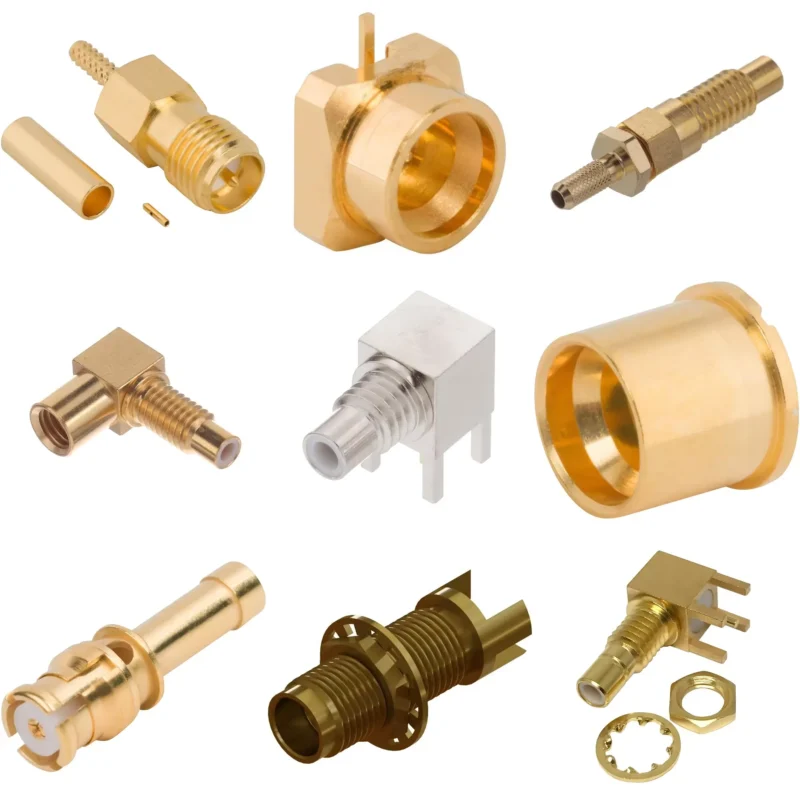
A dummy load can be correctly matched at one frequency and still perform poorly at another.
When engineers specify a dummy load, the operating frequency should always be confirmed first.
A typical selection process starts with:
- What frequency band will be tested?
- Is the application below 1 GHz, several GHz, or microwave range?
- Is the load used for power absorption or precision measurement?
- How much frequency margin is required?
For example:
A dummy load used for a 900 MHz communication system and a dummy load used for a 26 GHz microwave test system may both be labeled as “50 ohm loads”, but their internal structures are completely different.
At higher frequencies, the electrical performance becomes more sensitive to:
- connector geometry
- resistor construction
- internal transition design
- dielectric material
- manufacturing tolerance
Check operating frequency instead of only impedance rating
A common purchasing mistake is:
“The system is 50 ohm, so any 50-ohm dummy load should work.”
This assumption is incorrect.
A dummy load specification should normally include both impedance and frequency range.
Example:
| Dummy Load Specification | Suitable Application |
| 50Ω DC–1 GHz | Low-frequency RF testing |
| 50Ω DC–6 GHz | Wireless modules, general RF testing |
| 50Ω DC–18 GHz | Microwave laboratory testing |
| 50Ω Above 18 GHz | Precision microwave applications |
The operating frequency should not exceed the rated range of the load.
A load used close to its upper frequency limit may also require additional attention because:
- VSWR may increase
- return loss may degrade
- measurement uncertainty may increase
For production testing, engineers usually prefer some frequency margin rather than selecting a component that only barely reaches the required band.
Understand why RF loads behave differently at higher frequencies
At DC or low frequencies, the resistor element dominates the electrical behavior.
At microwave frequencies, the entire structure becomes part of the circuit.
The following details can affect performance:
| Factor | Possible RF Impact |
| Connector geometry | Changes impedance transition |
| Internal conductor length | Adds unwanted inductance |
| Dielectric material | Changes capacitance behavior |
| Assembly tolerance | Affects repeatability |
| Heat structure | Changes long-term stability |
This is why two dummy loads with the same connector and power rating may produce different VNA measurements.
For example, a small SMA dummy load may be suitable for:
- RF module testing
- signal generator verification
- cable assembly checks
A larger high-power coaxial load may be required for:
- transmitter output testing
- amplifier burn-in
- communication equipment validation
The correct choice depends on the complete test condition.
Which Connector Interface Should You Choose for a Dummy Load?
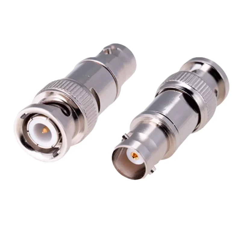
The connector is not only a mechanical connection point. It also affects the RF transition between the equipment and the load.
Common dummy load interfaces include:
- SMA
- N Type
- BNC
- TNC
The correct connector depends on the equipment interface, frequency range, and power requirement.
Match SMA, N-type, BNC, and TNC loads to the RF equipment
| Connector | Typical Use | Selection Consideration |
| SMA | RF modules, test cables, laboratory equipment | Compact size, commonly used to GHz range |
| N Type | Higher-power RF systems, outdoor equipment | Larger structure and stronger mechanical design |
| BNC | Laboratory instruments, lower-frequency RF testing | Quick connection design |
| TNC | Mobile and vibration environments | Threaded connection improves stability |
The connector should be selected together with the RF system.
A common mistake is adding multiple adapters simply because the load interface does not match the equipment.
For example:
Equipment port:
SMA → Adapter → N Type → Adapter → Dummy Load
The system may still work, but every additional transition introduces:
- insertion loss
- mismatch possibility
- mechanical tolerance
- additional failure points
For precision RF measurements, fewer transitions usually produce more repeatable results.
Check gender and polarity before ordering an RF load
Connector naming alone is not enough.
A wrong polarity component may physically appear close to correct while failing electrically.
A complete RF load specification should include:
Connector type + gender + polarity + impedance + frequency range + power rating
This information avoids many procurement errors.
How Can You Test a Dummy Load Before Using It in an RF System?
A new dummy load should not be judged only by appearance.
A connector may look perfect while the RF characteristics are outside the expected range.
Testing normally includes both mechanical inspection and RF measurement.
Perform a visual and mechanical inspection first
Before connecting the load to expensive RF equipment, check:
| Inspection Item | Purpose |
| Connector threads | Prevent poor mechanical mating |
| Center contact | Check damage or deformation |
| Housing | Confirm physical condition |
| Label marking | Verify model and specification |
| Mounting surface | Check mechanical stability |
These checks are simple but useful.
A damaged connector can create measurement errors that appear to be caused by the RF device under test.
Verify RF behavior with VNA measurements
For microwave applications, engineers usually verify dummy loads with a vector network analyzer (VNA).
Typical measurements include:
- S11
- VSWR
- Return Loss
The purpose is to confirm whether the load behaves close to an ideal matched termination.
Example test record:
| Frequency | S11 | VSWR | Return Loss |
| Low Band | Record Value | Record Value | Record Value |
| Mid Band | Record Value | Record Value | Record Value |
| High Band | Record Value | Record Value | Record Value |
A single measurement point may not show the complete behavior.
A load may perform well at 1 GHz but degrade near the upper frequency limit.
How Do You Specify the Right Dummy Load for a Project?
Many ordering problems happen because the request only includes:
“Need 50 ohm dummy load.”
This description is incomplete.
A supplier still needs to know the actual RF condition.
RF Dummy Load Specification Checklist
Before requesting a quotation, prepare the following information:
| Parameter | Example |
| Impedance | 50Ω |
| Frequency Range | DC–6GHz |
| Connector Type | SMA Male |
| Power Rating | 2W CW |
| VSWR Requirement | ≤ specified value |
| Application | RF testing / transmitter testing |
| Environment | Laboratory / Outdoor |
| Cooling Condition | Natural air / Forced air |
A complete requirement statement may look like:
50Ω SMA male dummy load, DC–6GHz, 2W continuous power rating, laboratory RF testing application, low VSWR requirement.
This gives the supplier enough information to recommend the correct structure.
Select based on the complete system instead of one specification
A dummy load selection should balance:
- impedance
- power handling
- frequency range
- connector interface
- measurement accuracy
- operating environment
The highest wattage option is not always the best choice.
A large high-power load may be unnecessary for a small RF module test.
A compact SMA dummy load may be the better option if the application is:
- short-duration testing
- low-power measurement
- laboratory verification
The opposite is also true.
A small 1 W or 2 W SMA load should not replace a high-power load connected to a transmitter output.
The component must match the actual RF condition.
FAQ
Why does a dummy load have a frequency limit?
The limit comes from the complete RF structure, including the resistor element, connector transition, internal geometry, and material properties.
Should I select a higher power dummy load than my transmitter output?
Usually, some safety margin is recommended. The correct margin depends on continuous power, pulse conditions, duty cycle, and cooling environment.
Why can two 50 ohm dummy loads give different VNA results?
Because “50 ohm” is only the target impedance. The actual RF response depends on the resistor structure, connector transition, dielectric, assembly tolerance, and the frequency being tested. Two loads may both measure close to 50Ω with a multimeter and look nearly identical, yet show different S11 near the top of the band. This becomes more noticeable at microwave frequencies. If repeatability matters, compare the loads across the full frequency range rather than at one test point.
Should I avoid adapters when connecting a dummy load?
If you can use the correct connector directly, that is usually the cleaner setup. An SMA-to-N adapter or a longer adapter chain may be electrically usable, but every extra interface adds another place for mismatch, mechanical play, and measurement variation. This matters more when you are checking low VSWR or working near the upper frequency limit of the test setup. For routine low-frequency work the effect may be small, but for precision RF testing, fewer transitions make troubleshooting easier.
What information should I send a supplier when requesting an RF dummy load?
Do not send only “50 ohm dummy load.” Include the connector type and gender, frequency range, power level, whether the signal is CW or pulsed, and any VSWR requirement. The application helps too. A load for a small RF module is not selected the same way as one for a transmitter output stage. A useful request could be: “50Ω SMA male load, DC–6 GHz, 2 W CW, for laboratory RF testing, with low VSWR across the operating band.”
Final Buying Guidance
A dummy load is a small RF component, but it directly affects the reliability of RF testing.
The correct selection is not determined by connector size alone.
Before ordering, confirm:
- 50Ω impedance
- operating frequency range
- power rating
- signal type
- connector interface
- VSWR requirement
- test environment
For RF systems operating near the upper frequency limit or power rating, providing the complete application information before purchase can prevent incorrect substitutions and repeated testing.
A suitable dummy load should match the RF system it is connected to, not just the connector on the cable.
