
An unused RF port can look harmless on the bench. Nothing is connected to it, the rest of the system powers up, and the signal path may still appear functional.
Then the VNA trace changes when a switch state is altered. A splitter behaves differently after another branch is connected. A test fixture gives one result with an open port and another after a 50-ohm load is installed.
That is where an RF terminator starts to matter.
The issue is not simply whether a connector can be capped. The open port is part of the RF network. If that port is expected to see a defined impedance, leaving it open can send reflected energy back into the system and change the conditions seen by the other components.
Before selecting a terminator, check three things first: where the RF path actually ends, what impedance the system is designed around, and whether the device at that point is expected to absorb signal power.
Where Does an RF Terminator Belong in the Signal Path?
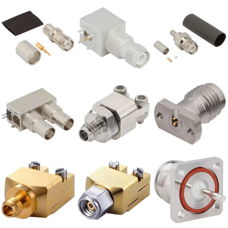
Start with the RF path, not the product photo.
A practical trace looks like this:
Source → Connector → Coax → Adapter → Device → Final Port
If the final port is unused but electrically active, that is one of the first places to check for termination requirements.
Common examples include unused outputs on power dividers, unused switch ports, test-fixture branches, RF modules, signal-generator paths, and measurement setups. The exact requirement still depends on the equipment design. “Unused port” does not automatically mean “install any 50-ohm load.”
Identify the open RF ports that can create reflected energy
A transmission line does not stop behaving like a transmission line just because nothing has been screwed onto the connector.
At the load end, the RF wave sees whatever impedance is present. If the line is designed for 50 ohms and the end is also close to 50 ohms, very little energy should be reflected because of that load. If the end is open, shorted, or significantly mismatched, the reflected component becomes much larger.
This matters in real systems because the reflected signal can change standing-wave conditions and the impedance presented elsewhere in the network.
A splitter is an easy example. Suppose one output feeds a receiver while another output is left open. The unused branch may not be electrically irrelevant. Depending on the splitter design and the manufacturer’s requirements, terminating that branch can be necessary to preserve the intended network conditions.
The same logic applies to RF switches and multiport fixtures. Do not decide from connector count alone. Check which ports are active in the selected operating state and what termination the equipment specification expects.
Separate a terminator from an adapter, attenuator, and matching pad
A sourcing mistake appears surprisingly often here: four small coaxial components may have similar metal bodies and the same SMA interface, yet perform completely different jobs.
| Component | Main Job | What It Does Not Primarily Do |
| RF terminator | Ends a transmission path with a defined impedance | Change connector format |
| RF adapter | Changes the mechanical/electrical interface | Intentionally absorb the full signal as a load |
| RF attenuator | Reduces signal level by a specified amount | Simply close an unused port |
| Matching pad | Interfaces different impedances with intentional loss | Act as a basic connector adapter |
This distinction matters when purchasing from photos.
A component marked “50 Ω” is not automatically a terminator. A 10 dB attenuator may also be a 50-ohm component, but it is intended to pass a reduced signal between two ports. A terminator normally has one RF interface because the signal path ends there.
Likewise, adding an SMA-to-BNC adapter to an open port does not terminate the path. It only changes the interface. The far end is still electrically open until an appropriate load is installed.
Why does a matched load reduce reflections?
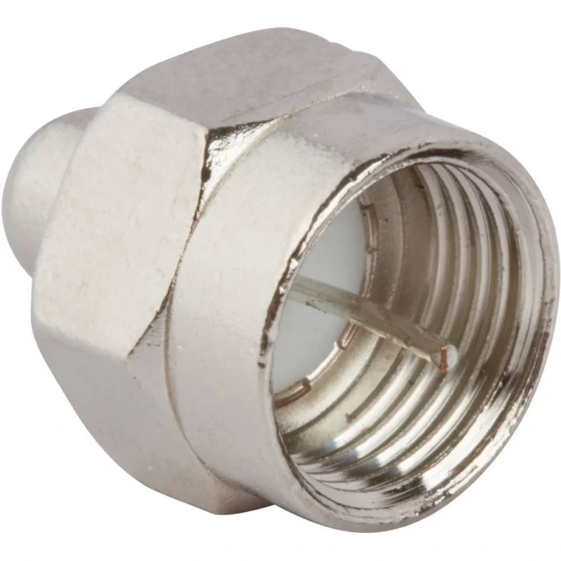
That is the ideal simplified case: no reflection caused by the load mismatch.
Real RF hardware is less tidy. At GHz frequencies, the impedance of a coaxial terminator is not perfectly resistive or perfectly constant. Connector geometry, dielectric structure, parasitic inductance, capacitance, and the resistor construction all affect the result. That is why a nominal 50 ohm termination should eventually be judged by frequency-dependent S11, return loss, or VSWR rather than by the printed resistance value alone.
How Can You Confirm System Impedance Before Adding a Terminator?
Do not begin with the marking on the terminator. Trace the whole chain.
A 50-ohm load cannot repair an RF path that already contains the wrong coax, a 75-ohm device, or an incorrectly specified interface.
Trace impedance from the source through the cable to the final port
Check each stage:
Source → Connector → Coax → Adapter → Device → Terminator
Write the nominal impedance beside every item.
This sounds basic, but it catches a common procurement problem: the connector mechanically fits, so the part is assumed to be electrically compatible.
A BNC interface is a good example because both 50-ohm and 75-ohm systems exist. A mechanically mateable BNC connection does not prove that the entire path has the same characteristic impedance.
Keep 50-ohm RF systems separate from 75-ohm video chains
Most general RF test, radio, wireless, and microwave equipment is built around 50-ohm transmission systems. Video, CATV, and many broadcast distribution systems commonly use 75 ohms.
Those numbers are not interchangeable simply because the connectors look similar.
That does not mean every real 50-to-75-ohm connection reflects exactly 4% across frequency. The calculation assumes ideal, purely resistive impedances. It is useful as a quick mismatch illustration, not as a substitute for an RF measurement.
An open circuit represents the more extreme case. As load impedance approaches infinity, the magnitude of the reflection coefficient approaches 1. In the simplified model, essentially all incident power is reflected rather than absorbed by the load.
This is why “nothing connected” and “50-ohm terminator connected” are electrically very different conditions.
That distinction becomes important in the next stage of selection, where power handling and frequency rating determine whether a nominally correct terminator can safely absorb the actual signal.
How Much Power Must an RF Terminator Safely Absorb?
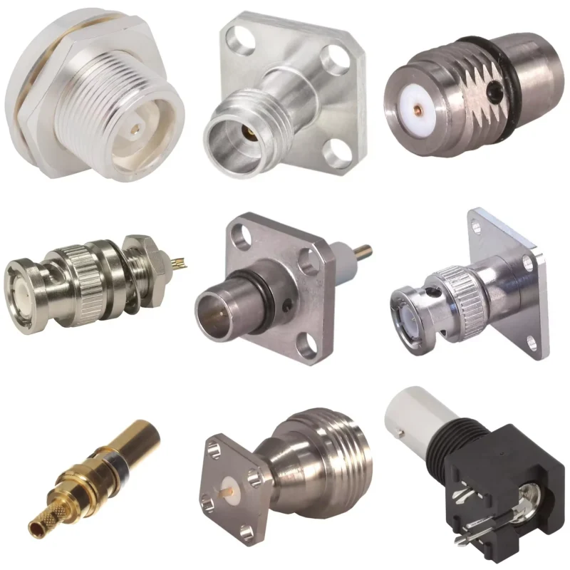
A terminator can have the correct impedance and still be the wrong part.
The usual failure is power. A small 50 ohm dummy load may look suitable because the connector matches and the label says 50 Ω, but its resistor and body still have to convert the incoming RF energy into heat. Exceed that thermal capability and the load can drift, overheat, or fail.
Start with the signal reaching the termination point—not the transmitter’s headline power rating.
Convert voltage or dBm into actual load power
A 30 dBm source corresponds to 1 W. That immediately changes the selection question. A 1 W terminator operated continuously at that level has essentially no nameplate margin.
The source level also needs to be checked at the actual port. Splitter loss, attenuation, cable loss, amplifier gain, and switching configuration can all change how much power reaches the RF load.
Treat CW, pulse, and intermittent signals differently
A 10 W pulse does not automatically require the same thermal design as 10 W continuous-wave operation. It also does not mean that a 1 W terminator is safe.
A 10 W pulse at 10% duty cycle produces an average value of 1 W. That number is useful for thermal estimation, but it does not prove that a 1 W load can survive the 10 W instantaneous pulse.
The resistor structure may have a separate peak-power limit. Pulse width matters. Repetition rate matters. So does how quickly heat can move from the resistive element into the body.
If the manufacturer gives only a CW rating, do not invent a pulse rating from the average-power calculation.
Leave margin instead of running at the nameplate limit
Ambient temperature is easy to overlook in a lab specification. A load rated at a certain power under favorable conditions may run considerably hotter inside an enclosure with poor airflow.
Check:
- continuous versus intermittent operation
- ambient temperature
- ventilation
- nearby heat sources
- connector heating
- possible source peaks
- manufacturer derating information
A terminator that is comfortable at 40–50% of its rated CW power gives much more room for production variation than one operated continuously at 95–100%.
RF Terminator Power Margin Calculator
This calculation can be used as a first-pass sourcing tool before a detailed datasheet review.
| Input / Result | Value to Record |
| System impedance | 50 Ω / other |
| Signal format | CW / pulse / intermittent |
| Source power | dBm or W |
| Vrms / Vpp | If applicable |
| Peak pulse power | W |
| Duty cycle | % |
| Calculated required power | W |
| Terminator rated power | W |
| Operating temperature | °C |
| Rated-power utilization | % |
How Should Frequency Range Change Your Terminator Selection?
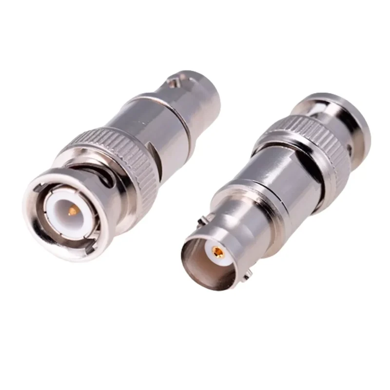
A multimeter reading of 49.8 Ω can be reassuring.
It can also be misleading.
DC resistance tells you whether the resistor is approximately where expected at very low frequency. It does not show what the complete coaxial structure does several gigahertz later.
Do not treat a 50-ohm DC reading as GHz qualification
As frequency rises, the terminator is influenced by more than the resistor value:
- lead and structure inductance
- parasitic capacitance
- connector geometry
- dielectric dimensions
- center-contact position
- assembly tolerance
That means two loads can both read close to 50 Ω on a DMM while producing noticeably different S11 traces at 6 GHz.
A DC measurement is useful for incoming inspection. It is not an RF qualification.
Read the frequency rating together with return loss or VSWR
Labels such as:
- DC–1 GHz
- DC–3 GHz
- DC–6 GHz
- DC–18 GHz
should be read as verified operating ranges, not as decorative maximum-frequency numbers.
“50 Ω” describes nominal impedance. Frequency-dependent S11 shows how closely the actual component continues to behave like that impedance across the band.
That distinction is especially relevant near the upper edge of the published range.
A DC–6 GHz SMA load used at 5.8 GHz deserves more attention to the manufacturer’s VSWR or return-loss data than the same load used at 100 MHz.
For related connector limits, see SMA frequency limits from 6 to 18 GHz.
Avoid extending a DC–6 GHz load into an unverified 10 GHz application
Suppose an available SMA terminator is rated:
50 Ω / 1 W / DC–6 GHz
The system operates at 10 GHz.
The connector may physically mate. The resistance may measure close to 50 Ω. Neither fact extends the verified RF range to 10 GHz.
The correct selection sequence is:
Application frequency → required bandwidth → connector → S11/VSWR → power → final terminator
If no RF data exists above 6 GHz, choose a load with a published operating band that covers 10 GHz instead of assuming the lower-frequency component will remain matched.
Which Connector Interface Fits Your RF Port Correctly?
Once impedance, power, and bandwidth are established, the front interface still has to mate correctly.
Do not solve a specification problem by stacking adapters unless there is a good reason.
| Interface | Coupling | Common RF Context | Selection Concern |
| SMA | Threaded | RF modules, antennas, test equipment | Polarity, torque, GHz range |
| BNC | Bayonet | Oscilloscopes, generators, lab setups | 50 Ω vs 75 Ω |
| N-type | Threaded | Higher-power and outdoor RF | Size, power, sealing |
| TNC | Threaded | Vibration-prone RF equipment | Interface and frequency |
The connector family does not determine the complete load specification, but it determines whether the terminator can be installed directly and repeatably.
Verify center contact and thread arrangement on SMA interfaces
SMA selection requires more than “male or female” based on a quick photograph.
Check both:
- thread arrangement
- center pin or socket
Standard SMA and reverse-polarity versions can create purchasing mistakes when the buyer identifies only the outer thread.
A proper BOM should record the exact mating interface rather than relying on “SMA terminator” alone.
Avoid extra adapters just to make the load fit
An adapter can solve a genuine interface transition. It should not be the default answer to a poorly specified terminator.
Every extra transition adds another:
- connector interface
- mechanical joint
- impedance discontinuity
- wear point
- measurement variable
For a permanent test fixture or repeatable production setup, a terminator with the correct native interface is usually easier to control than an adapter-plus-load stack.
How Do RF Terminator, Dummy Load, and Termination Load Differ?
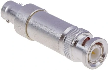
RF termination components designed to absorb RF power while maintaining a 50 ohm impedance for testing, measurement, and communication systems.
Product naming is less standardized than buyers sometimes expect.
A small SMA component may appear online as an SMA terminator, SMA 50 ohm load, SMA dummy load, or 50 ohm SMA terminator. Those labels often overlap.
The engineering specification matters more than the storefront wording.
Use RF terminator when the main job is ending a transmission path with a defined impedance.
Use RF dummy load when power absorption is the dominant part of the application, particularly around transmitters, amplifiers, or power testing.
But do not treat those terms as rigid product classes.
Before substituting one for another, compare:
impedance → rated power → frequency range → VSWR/S11 → connector interface
A tiny 1 W SMA termination and a large transmitter dummy load may both be 50 Ω. Their jobs and thermal capability are obviously not the same.
How Can You Verify an RF Terminator with a VNA?
A terminator may pass a resistance check and still behave poorly at the top of its rated band.
That is where the VNA becomes useful. The goal is not to prove that the part contains a 50-ohm resistor. The goal is to see how much RF energy is reflected from the complete connector-and-load structure across the frequencies that matter.
Calibrate at the terminator interface
For a basic one-port check:
- Set the VNA frequency span for the intended application.
- Perform a one-port calibration.
- Move the calibrated reference plane as close as practical to the terminator interface.
- Inspect and connect the load.
- Sweep S11.
- Save the trace and compare it with the acceptance requirement.
Do not describe a general-purpose RF terminator as a VNA calibration load unless it is actually specified and characterized for calibration use.
A normal termination can be tested with a VNA. That does not make it a precision calibration standard..
Convert reflection into return loss and VSWR
Lower reflected energy corresponds to better matching. In practice, however, do not judge the part from one isolated number unless the specification calls for exactly that point.
A load intended for DC–6 GHz should be examined across the band.
For example:
100 MHz → 1 GHz → 3 GHz → 6 GHz
A terminator may look excellent in the lower range and gradually degrade near the band edge.
For more background on RF measurement terms, see VSWR and return-loss fundamentals.
Reconnect the terminator and measure again
Repeatability matters in production and test fixtures.
Disconnect the load, inspect the mating surfaces, reconnect it correctly, and repeat the sweep.
If the trace moves more than expected, investigate:
- connector wear
- thread damage
- contamination
- center-contact condition
- mating torque
- adapter movement
- VNA calibration stability
A single clean trace proves less than a repeatable result.
When Should You Reject an RF Terminator Before Installation?
Not every incoming part needs a full laboratory investigation. But visual inspection and basic screening can prevent obvious defects from reaching assembly.
Reject or quarantine parts with:
- bent or recessed center contacts
- damaged threads
- loose or rotating bodies
- obvious plating damage
- contamination
- abnormal DC resistance
The resistance check remains a screening step only. It does not replace RF testing.
Why Are High-Frequency Test Systems Raising the Bar for RF Terminators?
RF test equipment continues to extend into wider microwave and mmWave bandwidths.
Newer measurement platforms introduced in 2026 are targeting increasingly broad RF and microwave ranges, including systems extending well above traditional SMA application bands.
The practical consequence is simple: engineers have less room to treat every component marked “50 Ω” as frequency-independent.
At higher frequencies, small details become more visible:
- connector geometry
- mating repeatability
- dielectric transitions
- reference-plane position
- S11 variation
- interface condition
SMA remains useful across a large range of RF work, but precision systems moving upward in frequency increasingly rely on interfaces such as 3.5 mm, 2.92 mm, 2.4 mm, and 1.85 mm.
That does not mean a higher-frequency connector is automatically better for every system. It means the interface and load must be qualified for the frequency actually being measured.
How Do You Turn Operating Conditions into a Terminator Specification?
Before requesting a quotation, collect six values:
- System impedance
- Connector interface
- Gender or polarity
- Maximum operating frequency
- Continuous and peak power
- Required VSWR or return loss
Then add environmental requirements only when they matter:
- operating temperature
- vibration
- mating cycles
- outdoor sealing
- plating
- mechanical size
Do not specify a 40 GHz part for a 1 GHz application simply because the number looks better. Higher specification can increase cost without solving a real system problem.
FAQ
Can a multimeter prove that an RF terminator is good at 6 GHz?
No. A multimeter can check DC resistance and help identify an open, shorted, or obviously incorrect load. It cannot show how the terminator behaves at 6 GHz. High-frequency verification requires data such as S11, return loss, or VSWR.
Why can a 50-ohm terminator show poor S11 at high frequency?
Because the complete RF structure includes more than the resistor. Parasitic inductance, capacitance, connector geometry, dielectric construction, contact position, and assembly tolerance can all change impedance as frequency rises.
Can I use a DC–6 GHz SMA terminator on a 10 GHz RF port?
Do not assume that it will work correctly. If the load has only been specified through 6 GHz, use a terminator with published RF performance that covers 10 GHz.
Is an SMA terminator interchangeable with an RP-SMA terminator?
No. Check the outer thread arrangement and the center pin or socket. A similar-looking interface does not guarantee correct polarity or mating.
Should every unused RF splitter or switch port be terminated?
Not automatically. Follow the device topology and manufacturer requirements. In RF networks that require matched unused ports, proper termination is normally important. Other designs may behave differently.
Can a small RF terminator replace a transmitter dummy load?
Only if impedance, frequency, CW power, peak power, duty cycle, and thermal limits all meet the transmitter requirement. A 1 W SMA load should not be used for a high-power transmitter simply because both products are nominally 50 Ω.
Why can a terminator pass once and fail after reconnecting it?
Check mating torque, thread wear, contamination, center-contact damage, VNA calibration, and reference-plane movement. Re-mating repeatability is especially important in production fixtures and frequently used test ports.
