
A panel connector can look correct in the hand and still fail the equipment drawing.
The plug mates. The nut tightens. The first sample may even pass a continuity check. The mistake appears later, when the enclosure is already drilled, the rear wiring has no bend space, or the 8-pin layout was mirrored from the wrong viewing direction. That is the costly side of a bulkhead electrical connector: it is not just a connector purchase. It is an enclosure boundary, a wiring plan, a mating pair, and an inspection item.
This guide focuses on multi-contact electrical panel interfaces used for power, control, sensors, and signal wiring. It is deliberately separate from RF bulkhead content such as SMA, BNC, SMB, or N-type coaxial panel feedthroughs. If the job is a 50 ohm or 75 ohm RF path, the connector geometry, impedance, shielding, VSWR, and cable termination rules are different. For RF panel examples, see TEJTE’s SMA-KKY panel-fixed RF adapter. For multi-pin industrial wiring, stay with the electrical interface as a complete system.
How should the enclosure boundary define the connector architecture?
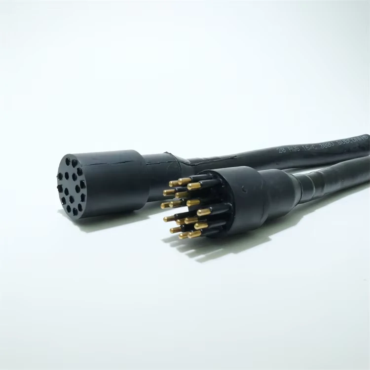
The multi-pin electrical cable connector assembly supports removable wiring connections and is commonly used in control equipment, automation systems, and electronic devices.
Start with the equipment wall, not the connector series.
A bulkhead interface exists because a circuit must cross a boundary: outside cable to inside equipment, removable harness to fixed control box, service plug to internal wiring, or field cable to device electronics. The word “bulkhead” describes that crossing. “Panel mount” describes the mechanical fixing method. They overlap, but they are not the same purchasing instruction.
A practical architecture card should answer these questions before the RFQ is sent:
| Field | Requirement |
| Exterior interface | Cable plug, field harness, removable service lead |
| Interior interface | Wire leads, solder cups, PCB tails, terminal wiring |
| Mounting side | Front mount or rear mount |
| Panel material | Metal, plastic, coated enclosure, chassis plate |
| Panel thickness | Drawing-controlled value |
| Connector retention | Nut, flange, thread, snap-in, locking hardware |
| Rear service space | Available depth after soldering or wiring |
| Cable direction | Straight, angled, downward, side exit |
| Environmental requirement | Dry cabinet, dust, splash, vibration, outdoor |
| Selected architecture | Cable-to-panel, wire-to-panel, panel-to-PCB |
A product family may offer several architecture routes under the same general connector name. TE Connectivity, for example, lists M12 panel-mount solder-cup connectors as a wire-to-panel system with 2, 3, 4, 5, 8, and 12 positions available in that family. That proves a useful point: contact count and mounting style belong to the same design conversation, but they are still separate approval fields. Source: TE Connectivity M12 Panel Mount Solder Cups.
For TEJTE-style sourcing, this is where GX-series products often enter the discussion. A GX12 aviation connector, GX16 aviation connector, or GX20 multi-core connector may all be described casually as aviation plugs or panel connectors. That casual name is not enough for production. The buyer still needs the pin count, plug/socket arrangement, thread size, panel cutout, wiring side, and mating pair confirmed.
The part number should not carry hidden assumptions. Write the interface requirement in plain engineering terms first:
“External cable plug mates to fixed panel receptacle. Internal side uses solder-cup wiring. Panel thickness 2.0 mm. Rear clearance 35 mm minimum. 8 contacts assigned for DC power, return, control, sensor, and reserved circuits.”
That sentence is more useful than “need an 8 pin connector” by itself.
Which contact count matches the power, control, and signal circuits?
A multi pin connector should not be selected by counting empty positions and hoping they become useful later.
List the circuits first. Power, return, protective earth, motor control, sensor output, enable line, communication pair, alarm contact, spare, shield drain: each one needs a defined role. Only then does the pin number make sense.
An 8 pin connector is common because it feels flexible without becoming too large. That can be useful, but only when all eight positions have a job. If a design needs four circuits today and no documented expansion path, an 8-position interface may add wiring errors, larger body size, tighter solder spacing, and unnecessary inspection steps. If the application genuinely needs power plus control plus feedback, an 8 pin circular connector can be the tidy option.
Use a pin assignment sheet before approving the contact count:
| Pin | Function | Wire Color | Voltage | Current | Power / Signal | Reserved? | Test |
| 1 | DC+ | Red | 24 VDC | Project spec | Power | No | Continuity |
| 2 | DC return | Black | 0 V | Project spec | Power | No | Continuity |
| 3 | Enable | Blue | 24 VDC | Low | Control | No | Continuity |
| 4 | Sensor signal | White | Project spec | Low | Signal | No | Continuity |
| 5 | Sensor return | Green | Project spec | Low | Signal | No | Continuity |
| 6 | Shield / chassis note | Bare / drain | Project spec | Low | Bonding / shield | Project-defined | Isolation check |
| 7 | Reserved | Yellow | None | None | Reserved | Yes | Mark NC |
| 8 | Reserved | Brown | None | None | Reserved | Yes | Mark NC |
The reserved pins matter. “Unused” is vague. “NC” means no connection. “Reserved for future alarm output” means the position should not be borrowed casually during production. “Do not populate” means the operator needs a drawing note.
Also keep contact count separate from current capability. Eight contacts do not automatically mean eight times the current. Current rating is usually per contact under stated conditions, and the final assembly depends on loaded contacts, wire size, ambient temperature, spacing, solder quality, and enclosure heat. If several contacts carry load at the same time, treat the connector as a thermal part of the system rather than a simple pin count.
A clean purchasing description may look like this:
“8 pin panel mount connector, fixed receptacle on enclosure, mating cable plug supplied together, solder-cup rear termination, pinout drawing required, current per loaded contact to be confirmed by supplier, no substitution without mating test.”
That is the difference between buying a connector and buying a controlled interface.
How do you size the panel opening without relying on the series name?
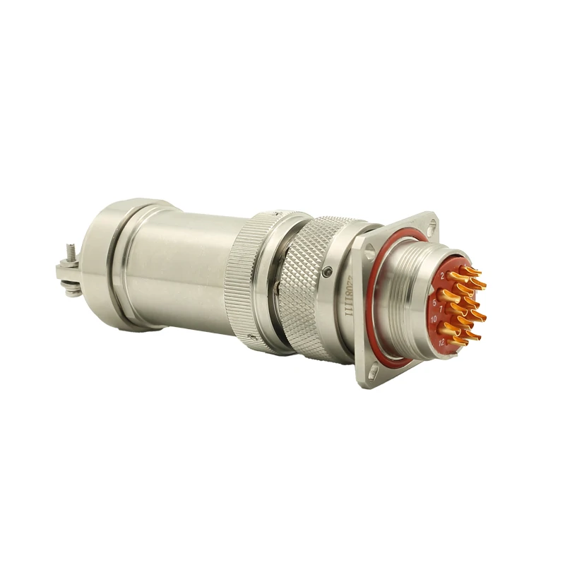
This bulkhead electrical connector features a circular multi-contact structure with secure panel mounting design, suitable for industrial control systems, automation equipment, and electrical wiring applications.
Do not machine the enclosure from the connector name.
This mistake is common with GX-style and metric circular connectors. A buyer sees GX16 and assumes the cutout is simply 16 mm. Another buyer sees M12 or M16 and assumes the panel hole follows the thread name. Sometimes the result is close enough for a loose prototype. Production does not reward “close enough” for long.
The dimensional drawing controls the cutout. Check the actual panel receptacle, not only the family name.
Before drilling or laser cutting, confirm:
| Check | Drawing Requirement | Enclosure Value | Pass |
| Cutout diameter / shape | Supplier drawing | Measured drawing value | Yes / No |
| Anti-rotation flats | Required or not required | Present / absent | Yes / No |
| Mounting thread | Exact thread and tolerance | Confirmed | Yes / No |
| Panel thickness | Minimum / maximum range | Actual material stack | Yes / No |
| Nut and washer clearance | Rear-side hardware space | Confirmed | Yes / No |
| Front mating clearance | Coupling shell can rotate or lock | Confirmed | Yes / No |
| Rear body clearance | Connector plus wiring fits | Confirmed | Yes / No |
| Adjacent connector spacing | Tool and hand access | Confirmed | Yes / No |
A panel mount connector also needs space around it. The front side may need finger access for coupling. The rear side may need room for a nut, solder cups, heat shrink, wire bend, and strain relief. Two connectors placed neatly in CAD may become impossible to wire by hand.
This is especially relevant for dense control boxes, power supplies, test fixtures, automation panels, and small equipment housings. The connector body may fit the hole, but the soldered wires may collide with a PCB, relay, fan, transformer, terminal block, or enclosure rib.
Use this approval gate before production:
Series / P/N → Latest drawing → Cutout geometry → Panel thickness → Fastener stack → Front clearance → Rear clearance → Mating clearance → DRILL APPROVED
A bulkhead electrical connector should never reach production with only a product photo and a series name. The panel drawing, mating pair, and wiring layout must travel together. Once the enclosure is drilled, every missing detail becomes more expensive.
Which side should be the cable plug and which side should be the panel receptacle?
Do not let “male” and “female” become the whole specification.
For a bulkhead interface, the more useful first question is: which side is fixed, and which side is removable? A common layout is simple:
Cable plug → fixed panel receptacle → internal wiring
That layout works well for many control boxes, test fixtures, machine panels, battery equipment, LED systems, sensor cabinets, and small automation enclosures. The panel side stays mounted. The external cable can be disconnected for service. The internal wiring remains protected inside the enclosure.
Still, the drawing should define the arrangement, not habit.
A panel mount receptacle may use pin contacts or socket contacts depending on the connector family. A plug may also be pin or socket. Some suppliers use “male/female” to describe contact gender. Others use it loosely for housing shape. In replacement projects, that difference causes real sourcing trouble. The connector may screw together but place the wrong contact type on the live side, reverse the wiring expectation, or fail the customer’s mating cable.
Use a mating-pair table before purchase:
| Check | Cable Side | Panel Side |
| Series | GX12 / GX16 / GX20 / M-series / project P/N | Matching series |
| Role | Plug or cable connector | Panel receptacle / bulkhead receptacle |
| Contact gender | Pin or socket | Pin or socket |
| Contact count | 4, 6, 8, 10, 12, etc. | Same approved layout |
| Keying | Straight / keyed / coded | Matching key |
| Coupling | Threaded / push-lock / bayonet | Matching coupling |
| Voltage rating | Project requirement | Same or higher |
| Approved mate P/N | Supplier-confirmed | Supplier-confirmed |
This is especially useful when replacing an unidentified legacy interface. The old part may only be described as “8 pin connector” or “aviation plug.” That is not enough. Sample mating should be checked physically, and the confirmed plug and receptacle should be purchased as a pair for the first build.
For TEJTE GX-series products, this is a practical point because models such as GX12, GX16, and GX20 are available in multiple pin counts and plug/socket combinations. A buyer should not approve only the front appearance. The mating part number, contact count, and wiring side need to match together.
How should voltage and current be allocated across multiple contacts?
Treat the published current value carefully.
A multi-contact connector is not a copper busbar. If one contact is rated for a certain current, that does not automatically mean every contact can carry that current at the same time under any enclosure condition. The final limit depends on the product datasheet, contact material, conductor size, loaded-contact count, ambient temperature, airflow, soldering quality, and insulation spacing.
Build a load budget before approving the connector:
| Pin | Circuit | Normal Current | Peak Current | Wire Size | Contact Limit | Simultaneous? |
| 1 | DC+ | Project value | Project value | AWG / mm² | Datasheet | Yes |
| 2 | DC return | Project value | Project value | AWG / mm² | Datasheet | Yes |
| 3 | Control enable | Low | Low | AWG / mm² | Datasheet | Yes |
| 4 | Sensor signal | Low | Low | AWG / mm² | Datasheet | Yes |
| 5 | Sensor return | Low | Low | AWG / mm² | Datasheet | Yes |
| 6 | Shield / bond | Project-defined | Project-defined | Project-defined | Datasheet | Project-defined |
| 7 | Reserved | 0 | 0 | None | N/A | No |
| 8 | Reserved | 0 | 0 | None | N/A | No |
Use that number as a planning check, not as a replacement for manufacturer derating data. If several contacts carry power at the same time, ask the supplier for the correct derating information or approve the assembly through test.
Voltage also needs discipline. A “250 V connector” should not be treated as a universal permission for every adjacent contact pair, every pollution environment, every wire combination, or every surge condition. Keep these values separate:
| Electrical Item | Why It Matters |
| Working voltage | Normal operating condition |
| Peak or surge voltage | Short-duration stress |
| Dielectric withstand test | Factory or qualification test |
| Insulation resistance | Leakage check between contacts |
| Contact current | Load carried by one contact |
| Loaded-contact count | Thermal condition when several contacts work together |
Modern industrial panel interfaces are also becoming denser. Phoenix Contact’s current circular connector portfolio, for example, shows device-side architectures using SMT, THR, wave soldering, front/rear mounting, and compact M5-to-M12 integration for signals, data, and power. The useful takeaway is simple: contact count, mounting style, PCB/wire architecture, and service strategy should be planned together, not after the enclosure drawing is finished. Source: Phoenix Contact circular connectors.
When does solder-cup termination make more sense than crimp or PCB tails?
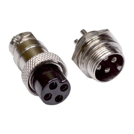
This circular electrical connector pair features compatible male and female interfaces, providing stable connections for industrial equipment, control systems, and electronic applications.
A solder cup connector can be the practical answer for prototypes, repair wiring, small-batch equipment, and field-custom harnesses. The operator strips the wire, tins if the process allows it, solders into the cup, inspects the joint, and routes the harness inside the enclosure. It is direct and flexible.
It is also operator-sensitive.
Too much solder can bridge adjacent contacts. Too much heat can damage insulation. Wire strands can escape the cup. In an 8-position connector, the pitch may be tight enough that a clean-looking joint still needs magnification. If the rear side will be potted, heat-shrunk, or bent immediately after soldering, the solder joint should not become the first mechanical stress point.
Crimp termination is usually stronger for repeatable production when the correct tooling exists. It gives better process control, faster assembly, and measurable pull-force inspection. The trade-off is tool cost, contact compatibility, and less convenient rework.
PCB tails fit a different architecture. They work when the connector should become part of the electronics assembly rather than a hand-wired panel harness. That can reduce manual wiring, but it also moves mechanical tolerance into the PCB and enclosure stack-up.
| Requirement | Solder Cup | Crimp | PCB Tail |
| Prototype flexibility | High | Medium | Low |
| Production repeatability | Process-dependent | High | High |
| Tool dependency | Medium | High | Assembly-process dependent |
| Rework | High | Medium | Low to medium |
| Dense wiring risk | Higher | Medium | PCB-layout dependent |
| Field wiring | Strong | Strong | Weak |
| Best use | Low-volume wiring, service, custom pinouts | Harness production | Device-side integration |
TE Connectivity lists M12 panel-mount solder-cup versions as wire-to-panel connectors and also offers related panel-mount wire and PCB variants. That product structure is a good reminder: termination style is not a small afterthought. It defines how the connector enters production.
How do you prevent mirrored pin numbering during assembly?
Pinout errors do not always look like wiring errors at first. The colors may be neat. The solder joints may be shiny. The connector may pass a quick “is something connected?” check. Then the equipment fails because pin 1 and pin 8 were read from opposite sides.
Every pinout drawing should state the viewing direction.
Use separate labels:
VIEW A = external mating face
Do not reuse one diagram for both plug and receptacle unless the drawing clearly says which side is being viewed. The mating face and rear solder side can appear mirrored. A plug and receptacle may also reverse the visual pattern depending on contact gender and orientation.
A front-to-rear translation sheet makes this harder to miss:
| Contact | Mating-Face Position | Rear Solder Position | Function | Wire Color |
| 1 | Drawing View A | Drawing View B | DC+ | Red |
| 2 | Drawing View A | Drawing View B | DC return | Black |
| 3 | Drawing View A | Drawing View B | Enable | Blue |
| 4 | Drawing View A | Drawing View B | Sensor signal | White |
| 5 | Drawing View A | Drawing View B | Sensor return | Green |
| 6 | Drawing View A | Drawing View B | Shield / bond note | Drain |
| 7 | Drawing View A | Drawing View B | Reserved / NC | Yellow |
| 8 | Drawing View A | Drawing View B | Reserved / NC | Brown |
Production should test by pin number, not by color alone. Wire color helps operators move faster, but it should not become the authority. The authority is the drawing, the contact number, the circuit function, and the continuity record.
For an 8 pin panel mount connector, test the first article point to point:
Pin 2 → Pin 2
Continue through all assigned contacts. Then check adjacent-pin isolation before applying operating voltage, especially after soldering.
This is where a bulkhead electrical connector becomes more than a catalog item. The connector is only correct after the mating pair, current allocation, termination process, and pin-view direction all agree.
How much rear clearance and strain relief should the panel reserve?
Measure the connector after wiring, not only the bare receptacle.
A catalog body length is useful, but it does not show the real rear stack. Once the wires are soldered, dressed, insulated, and routed, the required space becomes larger. The actual stack usually looks like this:
Panel → connector body → solder cups → insulation zone → wire bend → strain relief → harness route
If the enclosure drawing only reserves space for the metal connector body, the first build may force the wires into a sharp bend. That puts mechanical load directly on the solder joints. It may pass on the bench and fail after vibration, repeated service, or a few rounds of plug mating.
Use a rear-space stack-up calculator before approving the panel layout:
| Item | Measurement / Requirement |
| Connector rear body depth | Supplier drawing or sample measurement |
| Solder-cup zone | Actual soldered depth |
| Wire bundle OD | After all assigned wires are installed |
| Minimum bend space | Based on wire size and insulation |
| Strain-relief length | Heat shrink, clamp, tie point, boot, or bracket |
| Service clearance | Space for inspection or rework |
| Available enclosure depth | From panel inner wall to nearest obstruction |
| Result | Pass / redesign |
Formula:
Required rear depth = connector rear body + solder/terminal zone + controlled wire bend + service margin
Do not place a PCB, fan, relay, transformer, terminal block, or enclosure rib directly behind the connector until this stack is checked. A panel connector that fits the cutout can still be wrong if the wire exit has nowhere to go.
When do sealing, bonding, or harsh-environment requirements change the connector choice?
A metal shell is not automatically sealed. A threaded coupling is not automatically waterproof. A panel nut is not automatically a chassis bond.
Define the environment before locking the part number:
| Condition | Required Connector Feature |
| Dry control cabinet | Basic panel retention and insulation |
| Dust exposure | Gasket, covered interface, or dust cap |
| Splash | Mated sealing, panel seal, cable-side seal |
| Washdown | Confirmed IP rating in installed condition |
| Vibration | Locking hardware, strain relief, mating retention |
| Conductive chassis bonding | Defined shell-to-panel contact path |
| EMI / shield requirement | Shield termination and inspection method |
| Outdoor enclosure | UV, corrosion, sealing, temperature review |
The phrase “IP67 connector” needs context. Is the rating valid when mated only? Does it include the panel seal? Is the rear side protected? Does the cable plug carry the same rating? Phoenix Contact’s circular connector portfolio, for example, separates signal, data, power, and hybrid circular connector families and lists different protection, mounting, and connection options across the range. That is the normal industrial reality: sealing is configuration-specific, not a universal shell property. See Phoenix Contact circular connectors.
Bonding is another separate decision. The shell may be used only for mechanical mounting. It may also be used for protective bonding, shield continuity, or EMI control. If conductive contact to the chassis is required, define the surface, coating condition, washer stack, and inspection method. If electrical isolation is required, write that clearly too.
This is where the article must stay separate from RF bulkhead content. RF panel connectors care about impedance, coaxial shielding, return loss, and frequency behavior. A multi-pin electrical bulkhead connector cares more about contact assignment, voltage spacing, current loading, enclosure sealing, and wiring control.
Prove the first article before drilling the production enclosure
The first article should test the complete interface, not just the connector.
Check the mechanics with the actual mating pair. Install it into the real panel thickness or a matching test coupon. Confirm the nut or flange seats correctly. Mate and unmate the cable plug. Rotate the coupling shell if required. Make sure an operator can access the connector without hitting adjacent parts.
Then verify the wiring.
| Test | Method | Acceptance |
| P/N and mating pair | Drawing and physical mate | Correct |
| Panel fit | Install in real cutout | No interference |
| Contact assignment | Point-to-point continuity | 100% correct |
| Adjacent isolation | Electrical test | Meets project spec |
| Contact continuity | Electrical test | Pass |
| Solder workmanship | Visual inspection | No bridge, cold joint, loose strand |
| Mating retention | Mechanical check | Meets connector spec |
| Rear strain relief | Inspection | No solder-joint load |
| Final release | QA review | PASS |
For an 8-position connector, do not test only a few pins. Run every assigned circuit. Pin 1 to pin 1. Pin 2 to pin 2. Continue through all eight contacts. After soldering, adjacent-pin isolation matters because solder bridges and loose strands often hide in dense layouts.
If the application requires frequent maintenance, cycle the mating pair during approval. Some industrial circular connector families publish mating-cycle durability, which is a reminder that service frequency is a design requirement, not a footnote.
Build the RFQ and incoming inspection around the complete mating pair
A good RFQ starts with function before family name.
Do not send only “need 8 pin bulkhead connector.” Send the circuit count, voltage, current per contact, simultaneous loaded contacts, panel thickness, cutout, termination style, environmental condition, and mating requirement. If a cable plug is required, specify it as part of the same system.
Use this RFQ / IQC form:
| RFQ Field | Requirement |
| Application | Equipment type and operating environment |
| Contact count | 4, 6, 8, 10, 12, etc. |
| Cable plug P/N | Supplier-confirmed |
| Panel receptacle P/N | Supplier-confirmed |
| Pin / socket arrangement | Drawing-controlled |
| Voltage | Working and test requirement |
| Current per contact | Normal and peak |
| Simultaneous loaded contacts | Yes / no by circuit |
| Panel cutout | Drawing value |
| Panel thickness | Actual enclosure stack |
| Mounting direction | Front or rear |
| Coupling method | Threaded, bayonet, push-lock |
| Termination | Solder cup, crimp, PCB tail, wire lead |
| Wire range | AWG or mm² |
| Pinout drawing | Required |
| Environmental rating | Dry, dust, splash, outdoor |
| Mating-cycle requirement | Project-defined |
| Prototype quantity | Sample approval lot |
| Production quantity | Forecast or order quantity |
Incoming inspection should include correct P/N, contact count, mating fit, cutout dimensions, hardware, contact condition, solder-cup shape, continuity, and lot traceability. Increase IQC after any contact-layout change, insulator change, panel-thread change, supplier change, or solder-cup geometry change.
FAQ
How do I decide whether a bulkhead connector should have 4, 6, or 8 contacts?
List every required power, return, control, signal, shield, and reserved circuit first. Select the contact count only after every position has a defined function and the current/voltage requirements are known.
Can an 8-pin bulkhead connector carry power and low-level signals at the same time?
It can, but only if the exact connector, pin assignment, current loading, voltage spacing, grounding, and signal requirements support that design. Do not assume all eight positions can be loaded the same way.
Does a GX16 connector always require an exact 16 mm panel hole?
No. Use the dimensional drawing for the exact panel receptacle. Confirm cutout geometry, thread, panel thickness, washer/nut stack, and tolerance before machining.
Why does an 8-pin connector pinout sometimes look reversed during soldering?
The mating face and rear solder side are viewed from opposite directions. The drawing should label both views so production does not mirror the wiring.
Is a solder-cup connector better than a crimp connector?
Neither is universally better. Solder cups are practical for prototypes, service wiring, and lower-volume custom work. Crimping is often stronger for repeatable production when tooling and compatible contacts are available.
Does a metal bulkhead connector shell always need electrical contact with the chassis?
No. It depends on the grounding, bonding, shielding, and EMI design. If shell-to-chassis contact is required, define the surface and inspection method.
Can two 8-pin connectors mate but still be electrically incompatible?
Yes. They may share the same shell and contact count but use different pin assignments, voltage ratings, contact genders, keying, or current limits. Approve the mating pair and pinout together.
A bulkhead electrical connector is approved only when the panel, mating plug, contact map, load budget, termination process, rear clearance, and inspection standard agree. The connector is the visible part. The controlled interface is the real product.
