
Selecting a QMA connector involves more than replacing a threaded interface with a faster coupling method. The connector must still match the equipment port, cable construction, operating frequency, installation space, and expected service environment.
QMA connectors are commonly used in radio equipment, base stations, amplifiers, filters, test systems, and other RF assemblies where technicians need fast access to densely arranged ports. Their quick-lock design can eliminate routine coupling-nut torque and reduce the clearance required around each connection. However, these advantages only matter when the selected connector is fully compatible with the rest of the RF path.
Before ordering a QMA cable, adapter, or panel interface, document the two equipment ports, required cable, frequency range, mechanical routing, and environmental conditions. This prevents a convenient quick-lock connection from creating cable mismatch, excessive port loading, or an unnecessary chain of adapters.
For broader interface comparisons, review the RF Connector Guide before narrowing the design to QMA.
How does the quick-lock interface change the installation plan?
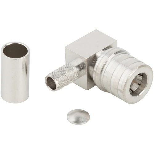
A right-angle QMA crimp connector with cable termination components, suitable for RF installations where a straight cable exit would create excessive bend radius or equipment-port loading.
A QMA connector uses a snap-on quick-lock mechanism instead of the threaded coupling nut found on an SMA connector. This allows technicians to mate and release the interface without rotating a coupling nut or using a torque wrench during normal connection.
The practical benefit becomes most visible in densely populated radio panels. When multiple RF ports are installed close together, there may be enough room to grip a connector but not enough room to position and rotate a wrench. A QMA interface can reduce this access problem while shortening assembly and service time.
Compare quick-lock mating with a threaded RF connection
A threaded connection normally requires the installer to align the interfaces, start the thread correctly, rotate the coupling nut, and apply the specified torque. Nearby connectors, enclosure walls, or cable bundles can interfere with this process.
A QMA quick-lock workflow is different:
- Align the QMA plug and jack.
- Push the interfaces together until the locking mechanism fully engages.
- Confirm that the connector is seated and retained.
- Route and support the cable without applying continuous side load to the port.
This tool-free process is useful for equipment that contains many RF connections or requires regular field servicing. It does not remove the need for careful alignment, cleanliness, cable support, or final inspection.
Separate quick mating from loose mating
“Quick-lock” does not mean that partial engagement is acceptable. A connector that appears attached but has not reached its correct locking position can create unstable contact, intermittent insertion loss, poor return loss, or complete signal interruption.
After mating, check that:
- The plug and jack are approved mating partners.
- The connector has reached its full engagement position.
- The locking sleeve is not damaged or obstructed.
- Light cable movement does not release the interface.
- The cable route does not pull sideways on the connector.
- The first cable clamp supports the cable’s weight.
These checks are especially important during first-article assembly, after a supplier change, or when technicians are using QMA connectors for the first time.
Use post-mating rotation only where the selected product permits it
Some QMA products allow 360-degree rotation after mating. This can help an installer reposition a cable or right-angle adapter without disconnecting the RF interface. Amphenol, for example, lists a rotatable quick-lock interface for its current QMA connector family.
Do not treat this as an automatic characteristic of every QMA connector. Confirm post-mating rotation on the exact manufacturer part number. Also remember that a rotatable connector does not make the cable immune to twisting, bending, or side loading.
Calculate a QMA Access Advantage Score
The following screening tool helps determine whether quick-lock access offers a meaningful advantage in a particular installation. Score each condition from 0 to 2.
| Installation factor | 0 points | 1 point | 2 points |
| Wrench clearance | Open | Limited | Very restricted |
| Connector density | Low | Medium | High |
| Service frequency | Rare | Occasional | Frequent |
| Cable orientation changes | None | Some | Frequent |
| Installation-speed priority | Low | Medium | High |
Which QMA gender belongs on each side of the RF path?
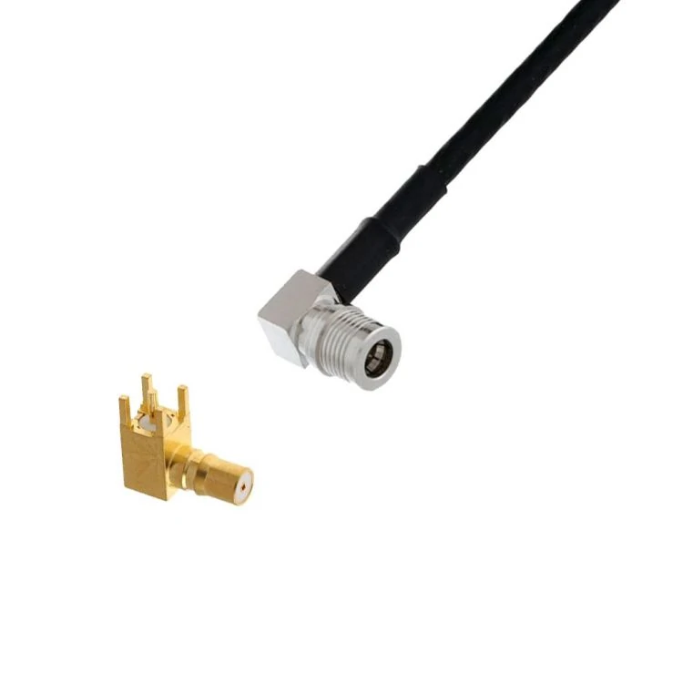
Example of right-angle QMA connector configurations used for coaxial cable and PCB connections where enclosure depth, port spacing, and cable routing must be considered.
Ordering errors often begin when a buyer specifies only “QMA male connector” or “QMA female connector” without recording the complete interface configuration.
Supplier terminology can vary, and casual male/female descriptions may focus on the connector body while overlooking the center contact. The safer approach is to identify the interface as a plug or jack and then confirm the center pin or socket using the manufacturer’s drawing.
Identify plug and jack before relying on male/female wording
For each side of the connection, record:
- Connector family
- Plug or jack
- Center pin or socket
- Cable, PCB, or panel mounting
- Straight or right-angle orientation
- Nominal impedance
- Frequency requirement
- Approved mating part number
This prevents the purchasing team from assuming that a QMA male connector is defined by only one visible feature. The locking body, center contact, and mounting role must all agree with the equipment drawing.
Keep connector gender separate from equipment direction
Do not assume that every radio port is female or that every cable end must be male. Equipment manufacturers may use different port configurations according to enclosure design, internal PCB layout, or cable-service requirements.
Instead of documenting:
Radio side: female Cable side: male
use a complete description such as:
Equipment Port A: QMA jack, center socket, 50Ω Cable Side A: approved QMA plug, straight crimp, for specified cable P/N
The actual interface drawing—not the expected signal direction—controls the decision.
Verify cable-mount, PCB, and panel roles separately
The term “QMA connector” does not define how the component attaches to the rest of the system. Available configurations may include:
- Straight cable plugs
- Right-angle cable plugs
- PCB-mounted jacks
- Panel or bulkhead interfaces
- In-series adapters
- Between-series adapters
A connector with the correct front interface can still be unusable if its rear termination, mounting geometry, or orientation does not match the design.
How should cable size and termination method shape the connector choice?
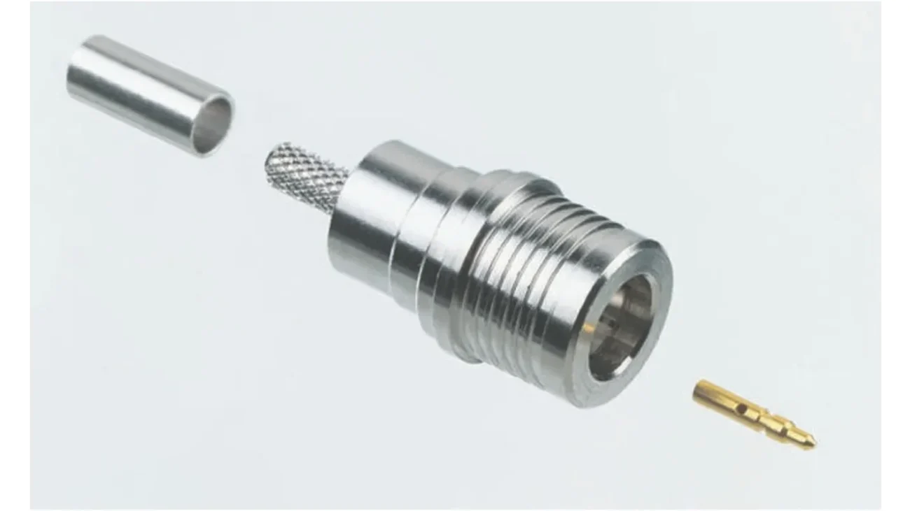
The cable should normally be selected before the rear geometry of the QMA connector is finalized. A QMA cable termination must match the actual coaxial construction, not merely a familiar RG designation or approximate jacket diameter.
This is important because the connector’s center contact, rear bore, ferrule, crimp dimensions, and strip lengths are designed around a specific cable group.
Select the cable before finalizing the connector
Start by recording the complete cable part number and the dimensions that affect termination:
- Jacket outside diameter
- Shield or braid diameter
- Dielectric diameter
- Center-conductor diameter and construction
- Cable impedance
- Minimum bend radius
- Temperature range
- Required flexibility
- Attenuation at the operating frequency
If the project has not yet selected a cable, compare the available options using the RF Coaxial Cable Guide before choosing the QMA termination.
Do not infer compatibility from similar outside diameters
Two coaxial cables can have nearly identical jacket diameters but require different connector parts. Differences may include:
- Solid versus stranded center conductor
- Single-braid versus double-braid shielding
- Different dielectric diameters
- Different jacket thicknesses
- Different ferrule compression requirements
- Different cable-preparation dimensions
For example, a connector advertised for one 5 mm cable should not automatically be used on every cable with an approximately 5 mm jacket. The connector drawing or approved cable list must confirm the assignment.
Match the crimp body to the exact coax family
Current QMA product families include cable plugs for several coax groups, such as RG58/RG141 and RG55/RG142/RG223/RG400. These groupings illustrate why buyers should verify compatibility at the exact connector part-number level.
A reliable cable-to-connector check should cover three separate interfaces:
- The center conductor to the connector contact
- The dielectric to the connector body
- The cable shield and jacket to the ferrule or crimp sleeve
If one of these interfaces is outside the specified range, the assembly may fail mechanically even when basic continuity appears normal.
Decide whether a straight or right-angle exit reduces port load
A right-angle QMA connector can help when an enclosure does not provide enough depth for a straight cable exit. It may also improve cable routing near a cabinet wall.
However, a right-angle body occupies more space around the port and creates a rotation envelope that may interfere with adjacent connectors. Compare:
- Enclosure depth
- Port spacing
- Connector-body diameter
- Cable bend radius
- Neighboring cable routes
- First cable-clamp position
- Technician release access
The best orientation is the one that maintains the required bend radius while keeping cable weight and leverage away from the equipment port.
When does QMA make more sense than SMA?
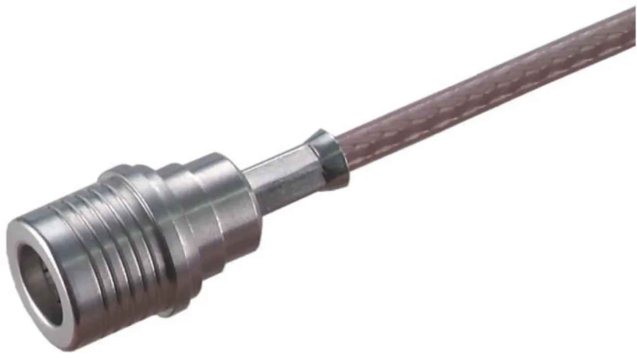
The QMA vs SMA decision should begin with installation and servicing requirements rather than a general assumption that one interface is better.
Both families can be used in compact 50Ω RF systems, but they solve different mechanical problems. QMA prioritizes rapid, tool-free access, while SMA provides a familiar threaded interface supported by a large ecosystem of cables, adapters, instruments, and components.
Compare service access before comparing headline frequency
QMA may be the stronger choice when the project requires:
- Fast connection and disconnection
- Closely spaced RF ports
- Limited wrench clearance
- Frequent field servicing
- Quick cable-orientation changes
- Reduced installation time across many ports
SMA may be more practical when the project requires:
- Direct compatibility with existing SMA equipment
- A torque-controlled threaded connection
- Broad instrument and accessory availability
- A specific precision or high-frequency SMA part
- Little or no routine servicing
For a detailed review of the threaded alternative, see the SMA Connector Guide.
Compare the complete connection workflow
QMA should not be treated simply as “SMA without threads.” It has its own interface design, mating mechanism, retention behavior, and approved component ecosystem.
A QMA design should be evaluated as a complete workflow:
Align → Fully engage → Confirm retention → Route cable → Support cable → Verify RF performance
An SMA workflow instead includes thread engagement and controlled tightening. The correct choice depends on which workflow better fits the installation and maintenance plan.
Include lifecycle labor in the connector decision
Connector price alone does not show the full cost of an RF installation. In equipment containing dozens of ports, the mating method can affect:
- Initial assembly time
- Tooling requirements
- Technician access
- Field replacement time
- Risk of incorrect tightening
- Downtime during servicing
A modest difference in component cost may be outweighed by repeated labor savings when technicians frequently access a high-density radio panel.
| Requirement | QMA priority | SMA priority |
| Tool-free mating | High | Low |
| Dense port spacing | High | Medium |
| Frequent servicing | High | Medium |
| Existing SMA equipment | Low | High |
| Torque-controlled threaded interface | Low | High |
| Quick cable repositioning | High | Low |
| Broad adapter and instrument ecosystem | Medium | High |
| Exact high-frequency P/N availability | Verify | Verify |
| Outdoor sealing | Product-specific | Product-specific |
The final selection must still be approved against the exact connector, cable, frequency, environment, and mating-cycle requirements. The next stage is to determine how QMA-to-SMA and QMA-to-N adapters affect the complete RF link.
How do QMA-to-SMA and QMA-to-N adapters change the link?
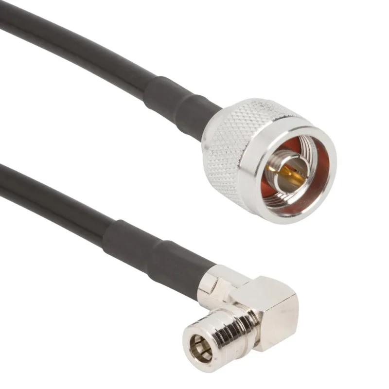
A QMA adapter is useful when equipment with a quick-lock port must connect to an existing SMA or N-Type cable, instrument, antenna, or RF module. The adapter preserves the coaxial signal path while changing the mechanical interface, but it also adds another mated transition that must be included in the RF and mechanical design.
The goal is not simply to find two ends that connect. The selected adapter must match both connector genders, maintain 50Ω impedance, support the operating frequency, and avoid placing excessive leverage on the smaller equipment port.
Use QMA to SMA when connecting with an SMA ecosystem
A QMA to SMA adapter is commonly used when quick-lock radio equipment must connect to:
- An SMA test cable
- A signal analyzer or power sensor
- An SMA antenna cable
- An amplifier or filter with an SMA port
- Existing laboratory fixtures
A typical path may be:
QMA equipment port → QMA-to-SMA adapter → SMA cable → test instrument
The reverse description, SMA to QMA adapter, may refer to the same passive transition. It does not necessarily indicate signal direction.
The complete part description should identify:
- QMA plug or jack
- SMA plug or jack
- Center-contact configuration
- Straight or right-angle body
- Nominal impedance
- Frequency rating
- Mechanical length
For additional guidance on the threaded side of the transition, review the SMA Adapter Guide.
Treat interface wording separately from signal direction
A conventional passive coaxial adapter does not normally have a designated RF input and output. Signals can travel through the adapter in either direction, provided that the frequency, power, impedance, and environmental requirements are satisfied.
For example, the following descriptions may refer to the same physical interface combination:
QMA plug to SMA jack adapter
SMA jack to QMA plug adapter
Procurement teams should therefore compare the actual interfaces and dimensional drawing rather than assuming that the order of the words defines signal flow.
Use QMA to N when a larger N-Type interface already exists
A QMA to N adapter may be needed when compact quick-lock equipment must connect to an N-Type antenna cable, feeder interface, surge protector, or outdoor RF component.
A typical connection may be:
QMA radio port → QMA-to-N adapter → N-Type cable → antenna system
The N-Type side is physically larger and may be connected to a heavier cable. A rigid adapter can transfer that cable weight and leverage directly to the smaller QMA equipment port. Where mechanical loading is a concern, a short supported cable assembly may be safer than a long or heavy rigid adapter.
Do not assume that the environmental capability of the N-Type side makes the complete transition waterproof. The QMA interface, adapter body, panel seal, and attached cable must each meet the outdoor requirement.
Count every transition before approving the architecture
An adapter can solve an immediate compatibility problem while creating a longer and less stable signal path.
Avoid structures such as:
QMA → SMA adapter → SMA gender changer → SMA-to-N adapter → N cable
when a direct QMA-to-N adapter or a purpose-built QMA-to-N cable assembly can remove unnecessary interfaces.
Each added connection can affect:
- Insertion loss
- Return loss
- Mechanical length
- Port loading
- Repeatability
- Troubleshooting time
- Long-term reliability
Which frequency rating should you trust for QMA hardware?
The family name alone does not define the usable frequency of a QMA connector. Traditional QMA applications are often associated with operation up to 6 GHz, while selected modern connectors and adapters are offered with ratings extending to 18 GHz.
These two statements are not contradictory. One describes the traditional standardized application range; the other describes the capability of specific current products.
Separate the standardized range from extended-frequency products
IEC 61169-50 covers 50Ω QMA coaxial connectors with a quick-lock system. It describes connectors normally used with flexible or corrugated cables for middle-power applications up to 6 GHz.
This provides an important reference point for interface dimensions, general performance considerations, and qualification. It does not mean that every QMA connector must stop operating at exactly 6 GHz.
Selected current QMA product families are rated to higher frequencies, including 18 GHz. Those extended ratings depend on the precise connector geometry, materials, cable assignment, assembly quality, and manufacturer validation.
A practical purchasing rule is:
“QMA equals 6 GHz” is not a safe universal limit, but “all QMA operates to 18 GHz” is equally unsafe.
Use the exact part-number datasheet
A supplier may offer several QMA products with different frequency limits under the same series name. Confirm the rating for the complete part number rather than relying on a category-page headline.
Check:
- Connector P/N
- Cable P/N
- Straight or right-angle structure
- Termination method
- Adapter interface
- Return-loss specification
- Finished-assembly test range
Right-angle connectors, cable terminations, and between-series adapters may not have the same frequency rating as a straight standalone interface.
Approve the lowest-rated element in the complete path
The complete RF link is limited by its lowest-rated component.
For example:
| Link element | Rated frequency |
| QMA connector | 18 GHz |
| QMA-to-SMA adapter | 18 GHz |
| SMA connector | 18 GHz |
| Attached cable | 6 GHz |
| Finished assembly | Tested to 6 GHz |
In this example, the approved assembly range should not exceed 6 GHz without additional validation. An 18 GHz connector does not upgrade a 6 GHz cable.
For RF-critical applications, use VNA measurements across the actual operating band. Record S11 and S21 after final cable routing because bending and connector orientation can change the assembled result.
Design dense radio panels around tool-free access
QMA removes the need for a torque wrench at the quick-lock interface, but it does not eliminate all access requirements. Technicians still need enough room to grip, mate, release, inspect, and route each connection.
A panel that looks compact in a CAD front view may become difficult to service after right-angle bodies, cable diameters, bend radii, and neighboring cable bundles are added.
Reserve hand clearance around every port
Provide enough space for a technician to:
- Hold the connector body
- Align the interfaces
- Push the connector to full engagement
- Operate the release mechanism
- Confirm that the connection is locked
- Remove the connector without pulling the cable
Wrench clearance may no longer be required, but finger clearance remains essential.
If a technician must pull on the cable rather than the connector body to release the interface, the layout should be revised.
Check port pitch against the complete connector geometry
Some QMA product families advertise a minimum pitch around 12.4 mm. Treat this as a product-specific reference rather than a universal panel-layout value.
The required pitch can increase when the design includes:
- Right-angle connectors
- Thick coaxial cable
- Molded strain relief
- Identification sleeves
- Cable boots
- Nearby panel hardware
- Manual release clearance
Create the panel layout using the exact connector drawing and cable bend radius.
Keep right-angle connectors from colliding
A right-angle QMA connector may rotate after mating when that feature is supported by the selected product. The designer should therefore evaluate the full rotation envelope, not only the body position shown in one drawing view.
Check for interference with:
- Neighboring QMA ports
- Adjacent RF adapters
- Enclosure walls
- Cooling ducts
- Cable clamps
- PCB components behind the panel
If rotation causes the elbow or cable to strike another component, limit the permitted orientation or increase the port spacing.
Validate at least one physical panel or representative mockup before finalizing a dense production layout.
How should outdoor and vibration-prone QMA links be qualified?
A standard QMA connector should not automatically be treated as waterproof or vibration-qualified. Environmental capability depends on the selected product, sealing structure, mounting method, cable support, and qualification plan.
Dedicated sealed QMA variants are available for demanding outdoor environments, but their protection ratings do not apply to unrelated standard QMA parts.
Do not assume every QMA connector is weatherproof
For an outdoor installation, verify:
- Connector IP rating
- Mated and unmated sealing condition
- Panel O-ring or gasket
- Cable-entry sealing
- Temperature range
- UV exposure
- Corrosion resistance
- Drainage and enclosure design
A sealed connector body does not protect an unsealed cable entry or incorrectly installed panel interface.
For related outdoor practices, see the RF Connector Installation and Waterproofing Guide.
Support the cable before evaluating the locking mechanism
A heavy or unsupported cable can apply continuous side loading to the QMA interface. In vibration environments, this load becomes cyclic and may produce movement, wear, or intermittent RF behavior.
Inspect:
- Cable mass
- First clamp position
- Bend radius
- Right-angle leverage
- Equipment vibration
- Repeated flexing
- Thermal expansion
- Technician handling
Connectors are intended to maintain the RF path, not to carry the full weight of a long cable run.
Separate environmental sealing from RF continuity
An assembly can pass a continuity test and still fail environmental qualification. It can also remain sealed while developing unacceptable RF reflection.
Evaluate these characteristics separately:
| Qualification area | Typical check |
| Mechanical retention | Pull, release, or vibration test |
| Weather sealing | Water-ingress or IP test |
| Corrosion resistance | Material and exposure requirement |
| Center continuity | DMM |
| Center-to-shield isolation | DMM |
| Return loss | VNA S11 |
| Insertion loss | VNA S21 |
| Re-mating stability | Before-and-after comparison |
The results should identify whether a failure comes from the locking mechanism, cable support, sealing structure, corrosion, or RF interface rather than grouping every problem under “QMA connector failure.”
Define the first-article test plan before volume production
A QMA connector can be mechanically compatible with its mating port and still fail the assembled RF requirement. Cable preparation, crimp position, center-contact depth, connector seating, and final cable routing can all change the result.
The first article should therefore represent the actual production configuration, including the approved connector, cable, termination process, adapter, routing condition, and test frequency.
Inspect connector identity before connecting the VNA
Confirm the mechanical configuration before beginning RF measurements:
- Correct QMA plug or jack
- Correct center-contact configuration
- Approved cable part number
- Straight or right-angle orientation
- Correct ferrule and crimp die
- Cable-preparation dimensions
- Full connector engagement
- Correct adapter interfaces
- No visible contact or plating damage
This prevents test time from being wasted on an incorrectly assembled or incorrectly identified sample.
Record the complete assembly description rather than writing only “QMA cable.” A useful identification format is:
QMA plug to SMA male cable assembly, 50Ω, specified cable P/N, 500 mm, straight connectors, tested across the required operating band
Run continuity and isolation before RF characterization
Complete basic electrical checks before connecting the assembly to a vector network analyzer.
Minimum checks include:
- Center conductor continuity from end to end
- Shield continuity from end to end
- No short between center conductor and shield
- Stable readings while the cable is moved gently
- No intermittent contact during connector rotation, if rotation is permitted
A cable can pass center continuity while having poor shield termination or unstable contact. Test the center and outer conductor as separate paths.
Continuity does not prove acceptable RF performance. It only confirms that the assembly does not contain an obvious open circuit or short circuit.
Measure the assembled link at the actual operating band
The VNA test range should cover the real system frequencies, not only a convenient low-frequency checkpoint.
Recommended measurements include:
- S11 at Port 1
- S21 through the assembly
- S22 where the opposite interface is also critical
- Re-mating repeatability
- Performance after final routing
- Performance after permitted connector rotation
S11 indicates how much signal is reflected at the input, while S21 shows the transmitted signal through the cable and connectors. Acceptance limits should come from the RFQ, engineering drawing, approved sample, or system loss budget.
Avoid testing only one narrow frequency when the assembly will operate across several cellular, Wi-Fi, GNSS, or test bands. A termination defect may appear as a localized rise in reflection that a single-point measurement misses.
Test the cable in its routed condition
A straight cable on a test bench may perform differently after it is installed inside a cabinet. Tight bends, connector side loading, and a rotating right-angle body can change the mechanical relationship between the cable and termination.
Compare the following states:
- Cable straight and unrestricted
- Cable routed to the intended bend radius
- Connector rotated to the installation position
- Assembly disconnected and re-mated
- Cable secured by the intended first clamp
Large movement between these measurements should be investigated before production approval.
How should buyers specify QMA parts without creating an adapter chain?
A complete QMA RFQ starts with the two installed equipment ports and the required cable path. Starting with an individual connector often results in a technically valid component that does not solve the complete connection problem.
Document the required path first:
Equipment Port A → Required cable and routing → Equipment Port B
Then determine whether the best solution is a direct QMA cable, a between-series cable assembly, or a single QMA adapter.
Start with both equipment ports
Record the following information for each end:
- Connector family
- Plug or jack
- Center pin or socket
- Nominal impedance
- Frequency range
- Equipment drawing or port P/N
- Available installation space
- Environmental exposure
- Expected connection frequency
Photographs can help identify an existing port, but they should not replace dimensional drawings when the connector is being released for volume production.
Write gender, cable, and orientation as separate fields
A useful description is:
QMA plug, 50Ω, straight crimp termination, for approved RG cable P/N, operating across the specified frequency band
Avoid descriptions such as:
QMA male connector for cable
The shorter description does not identify the exact cable, termination, frequency, center contact, or body orientation.
For a cable assembly, specify both ends independently:
Side A: QMA plug, straight Cable: Approved coax P/N, specified length Side B: SMA male, right-angle Impedance: 50Ω Test range: Defined by project
Check for a direct cable assembly before adding adapters
Use the following selection order:
- Look for a direct QMA-to-destination cable assembly.
- If unavailable, look for one suitable between-series adapter.
- Use stacked adapters only when no practical direct solution exists.
- Include every retained interface in the RF and mechanical test plan.
A direct QMA-to-SMA cable can often replace a QMA-to-SMA adapter plus a separate SMA cable. The direct assembly may reduce mechanical length, adapter count, and stress on the equipment port.
For larger transitions, compare the rigid-adapter arrangement with the mechanical guidance in the N-Type to SMA Adapter Guide. The same principle applies: a short flexible assembly may protect the smaller port better than a heavy unsupported adapter.
Screen incoming lots with mechanical and RF release criteria
First-article approval does not remove the need for incoming inspection. Connector dimensions, cable construction, crimp tooling, plating, and assembly processes can change between lots.
The incoming plan should focus on characteristics that can affect mating, retention, continuity, and RF performance.
Put visible mating defects under routine inspection
Routine inspection should check:
- Correct QMA plug or jack
- Correct center contact
- Undamaged locking sleeve
- No bent or recessed contact
- No body deformation
- Consistent plating
- Correct cable marking
- Correct connector orientation
- Complete ferrule crimp
- No exposed braid strands
- Correct heat-shrink position
- Legible lot identification
Interface identity and obvious contact damage are suitable for 100% inspection because they can normally be checked without destructive testing.
Sample quick-lock engagement after process changes
Increase engagement and retention sampling after:
- A new connector supplier is introduced
- The cable part number changes
- A crimp die is replaced
- Cable-preparation equipment is adjusted
- The connector drawing is revised
- Plating or material changes
- A previous locking or retention failure
- A long production interruption
Use an approved mating part or controlled fixture. A worn field connector should not serve as the only inspection standard because its mating feel may no longer represent the original interface.
Use RF sampling where dimensional drift matters
RF sampling becomes increasingly important as frequency rises or when the application has a tight return-loss budget.
Record:
- Test equipment
- Calibration method
- Test fixture
- Frequency range
- Cable routing state
- S11
- S21
- Sample quantity
- Lot number
- Operator
- Test date
Compare results with the approved first article. A lot may pass basic continuity while showing a shift in return loss caused by center-contact depth, cable preparation, dielectric position, or crimp variation.
| Characteristic | Method | Sampling | Acceptance | Failure action |
| Interface identity | Visual | 100% | Drawing | Quarantine |
| Center-contact condition | Visual | 100% | No damage | Sort |
| Locking-sleeve condition | Visual | 100% | No damage | Sort |
| Cable and marking | Visual | 100% | BOM | Quarantine |
| Lock engagement | Approved mating part | Defined sample | Approved limit | Expand sample |
| Cable retention | Pull test | Risk-based | RFQ limit | Hold lot |
| Center continuity | Electrical | Defined plan | Pass | Rework or sort |
| Shield continuity | Electrical | Defined plan | Pass | Rework or sort |
| Isolation | Electrical | Defined plan | Pass | Hold lot |
| S11 | VNA | Risk-based | RFQ limit | Investigate |
| S21 | VNA | Risk-based | RFQ limit | Investigate |
| Routed-condition stability | VNA comparison | Risk-based | Project limit | Investigate |
If a failure is found, separate the possible causes before deciding on rework or rejection. Check the connector, cable, tooling, operator, mating fixture, and test setup rather than assuming every failure originates from the QMA interface.
FAQ
Why would an RF designer choose QMA instead of SMA in a crowded radio enclosure?
QMA removes the need to rotate and torque a threaded coupling nut during normal mating. This can simplify access where RF ports are tightly spaced or frequently serviced. The final decision should still consider frequency, environment, mating cycles, cable type, retention, and exact part-number availability.
Does every QMA connector operate to 18 GHz?
No. IEC 61169-50 describes traditional QMA applications normally operating up to 6 GHz, while selected current QMA products are rated as high as 18 GHz. Approve the exact connector, adapter, cable, and finished assembly for the required frequency.
Can a QMA-to-SMA adapter carry RF in either direction?
A conventional passive QMA-to-SMA adapter normally has no dedicated RF input or output. It can carry signals in either direction when the connector genders, impedance, frequency rating, power level, and mechanical configuration are suitable.
Does a standard QMA connection need a torque wrench?
Normal QMA quick-lock mating is tool-free and does not require the coupling-nut torque used for a threaded SMA connection. The connector must still be aligned, fully engaged, inspected, and protected from cable side loading.
Can QMA connectors be used outdoors?
Only when the selected connector and complete installation provide the required environmental protection. QMA should not automatically be treated as waterproof. Verify the IP rating, mated sealing, panel gasket, cable entry, corrosion resistance, and outdoor qualification of the exact product.
What should be tested after terminating a QMA cable?
Confirm connector identity, cable compatibility, cable preparation, crimp condition, full mating, continuity, isolation, and retention. For RF-critical assemblies, measure S11 and S21 across the operating band and repeat the measurement after re-mating and final cable routing.
A reliable QMA connection begins with the complete RF path, not with the connector name alone. Confirm the equipment ports, QMA gender, cable dimensions, adapter count, frequency range, access requirements, and environmental conditions before ordering. Then validate the selected configuration through first-article testing and controlled incoming inspection.
