
The replacement connector looked close enough in the product photo. It was small, threaded, and attached to a vehicle antenna cable. The technician ordered it as an FME connector, then discovered that the thread would not engage and the center contacts did not match.
This is a routine sourcing failure. FME, SMA, TNC, and Mini-UHF parts may appear similar when photographed without a scale, but “small threaded antenna connector” is not a valid purchasing specification. Before cable type, frequency rating, or termination method is discussed, the interface itself must be confirmed.
How can you confirm a connector is FME before ordering a replacement?
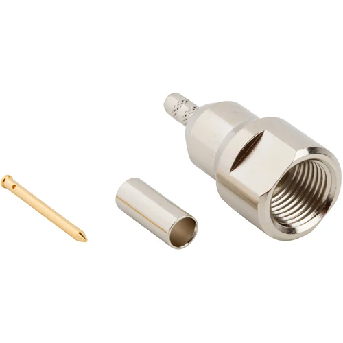
Internally threaded FME coaxial connector shown with a separate center contact and crimp ferrule for mobile antenna cable assembly and RF connection applications.
Start at the mating face. Do not start with the cable jacket, antenna location, or seller’s product title. Those clues may narrow the search, but they cannot prove the interface.
Identify the mating interface before measuring the cable
Record the complete connector geometry:
- Coupling mechanism: threaded, bayonet, push-on, or snap-on
- Approximate body and thread diameter
- Plug or jack configuration
- Center pin or socket
- External or internal mating thread
- Straight or right-angle body
- Cable-mount, panel-mount, or adapter construction
- Existing mating connector or adapter
- Equipment model and antenna part number
A clear front-facing photo is more useful than several side views. It should show the thread, dielectric, and center contact in the same frame. Add a ruler or caliper for scale, but do not approve the connector from one outside diameter alone.
Separate FME from SMA, TNC, Mini-UHF, and legacy radio interfaces
FME should not be identified only because the part is:
- Small
- Threaded
- Connected to an antenna
- Installed in a vehicle
- Used with thin coax
SMA is also compact and threaded, while TNC uses a larger threaded body. Mini-UHF and several older automotive radio interfaces can create further confusion when photos are cropped or taken at an angle. A connector may even appear to begin mating before incompatible threads or center contacts stop it.
The existing TEJTE guide to TNC, F, FME, and TV coax connectors provides a family-level comparison. For replacement work, the safer rule is stricter: match the physical interface to a drawing or an approved mating part.
Check the original equipment path before choosing a replacement
An FME part is often only one transition in a longer antenna path:
Antenna base → thin coax → FME cable end → adapter → radio or receiver
That architecture matters. The connector at the radio may be SMA, BNC, TNC, N-Type, Mini-UHF, or another interface, while FME remains on the cable because its smaller profile is easier to route through restricted spaces.
Removing the adapter and inspecting only the radio port can lead to the wrong conclusion. Photograph the complete connection before disassembly, then label every interface. The equipment manual, antenna cable label, previous purchase record, and adapter part number may confirm details that cannot be seen in a worn connector.
Which FME male or female end belongs on the cable?
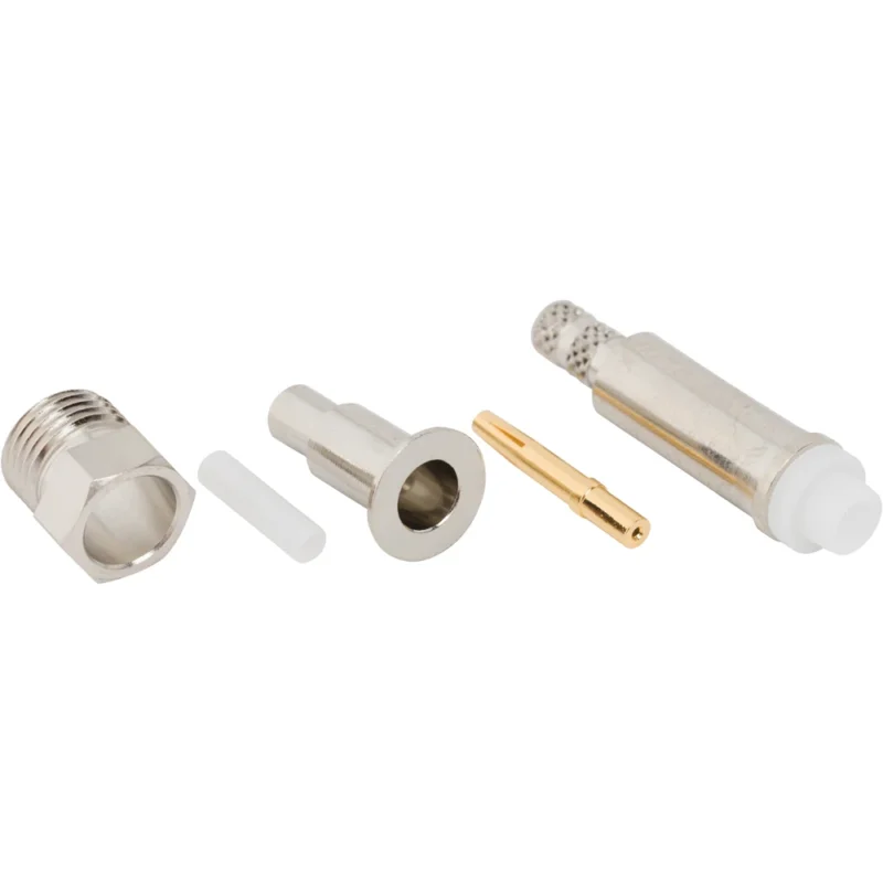
“FME female” is often entered into a purchase request without a mating photo or drawing. That is risky. Location does not determine gender, and the cable side is not automatically male or female.
Identify plug and jack independently from the antenna location
Inspect both sides of the connection. For each side, record:
- Connector family
- Plug or jack designation
- Center pin or socket
- Thread location
- Approved mating part number
Do not use rules such as “antenna side equals male” or “equipment side equals female.” FME connectors appear in cable ends, adapters, extensions, and panel configurations. The physical mating pair controls the selection.
Keep housing role and center-contact gender in one controlled naming system
Supplier listings may emphasize male/female, plug/jack, or center-contact gender. A short product title can therefore be misread when the drawing is missing.
Use one naming convention throughout the drawing, RFQ, purchase order, inspection record, and packaging label. A practical format is:
A current TE Connectivity FME jack example identifies the interface as FME, the connector style as jack, the impedance as 50 Ω, and the construction as cable-to-cable. It also links a product drawing. That level of detail is far safer than ordering from “FME female connector” alone.
Distinguish cable-to-cable from cable-to-panel configurations
The interface name does not define the mounting architecture. Two parts may both have an FME mating face while one terminates directly to coax and the other mounts through a panel.
For a cable connector, check the rear bore, ferrule, center contact, and termination process. For a panel connector, add the mounting-hole diameter, panel thickness, thread length, anti-rotation feature, and rear termination. These parts can mate at the front and still be unsuitable for the assembly.
A connector should not be released for purchase until both columns describe a valid mating pair. The next selection step is cable compatibility—because even a correctly identified FME interface can fail when the rear body, ferrule, or center contact does not match the coax.
How should coax dimensions control FME connector selection?
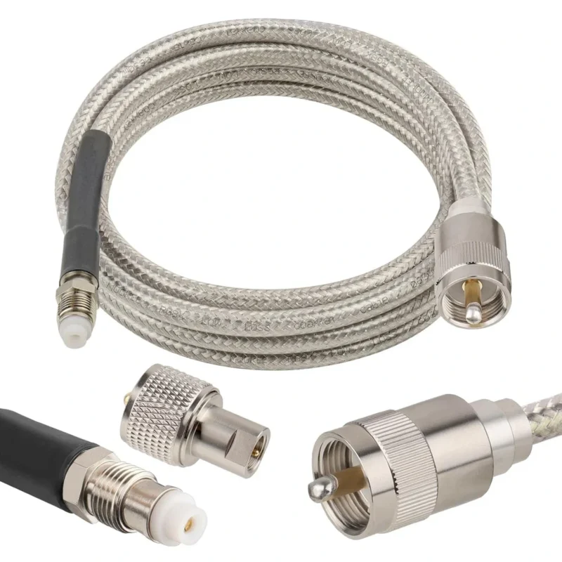
A confirmed FME mating face does not confirm cable compatibility. The front interface may be correct while the rear body is too large, the ferrule cannot grip the braid, or the center contact does not fit the conductor.
Match the cable before choosing the connector body
Record the actual cable part number whenever possible. If the marking is missing, measure:
- Jacket outside diameter
- Shield or braid diameter
- Dielectric diameter
- Center conductor diameter
- Shield construction
- Center conductor construction
- Jacket and dielectric materials
The RG cable guide is useful for comparing cable families, but nominal RG names are not enough for production approval. Manufacturer-specific tolerances, double-braid construction, jacket thickness, and conductor stranding can change the required rear bore, ferrule, and strip dimensions.
Two cables may have similar jacket diameters and still require different contacts or crimp tooling.
Treat cable compatibility as a part-number requirement
One current TE Connectivity FME jack is specified for RG174, RG174A, RG188A, and RG316 cable. That does not mean every FME female connector fits all four cable families. Compatibility belongs to that exact connector design and its approved termination process.
A substitute cable should therefore be checked against the connector drawing, not approved because its outside diameter “looks about the same.”
A continuity pass does not correct a loose ferrule or an oversized center-contact bore. Those faults often appear later as rotation, intermittent signal, or poor pull retention.
When should an FME cable be used instead of a rigid adapter?
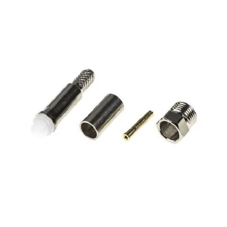
Exploded view of a compact FME cable connector with connector body, crimp sleeve, center contact, and threaded outer shell for vehicle antenna and RF cable installations.
The compact cable route is one of the main reasons FME remains useful. A thin FME cable can pass through a restricted opening before a larger equipment-side adapter is installed.
Preserve the small cable path in confined installations
An FME cable is usually the better architecture when:
- The coax must pass through vehicle trim or a narrow panel opening
- The radio-side connector is too large for the routing hole
- The antenna cable must be installed before the equipment
- The cable needs to follow an irregular route
- The radio may be removed for service
Replacing this arrangement with a larger connector and several rigid adapters may solve the interface problem on the bench while creating a routing problem in the vehicle.
Use cable flexibility to reduce port stress
A rigid adapter transfers movement directly into the radio port. That becomes risky when the equipment vibrates, the cable is pulled during servicing, or the installed assembly has no mechanical support.
A short flexible section can isolate some of that movement. It does not eliminate the need for strain relief, but it reduces the lever arm created by a long adapter stack.
Use this decision route:
- Must the cable pass through a narrow opening?
- Will the radio or antenna move during installation or service?
- Would the alternative require more than one rigid adapter?
- Can the cable be clipped or strain-relieved?
- Can the final adapter be supported close to the equipment?
Several “yes” answers favor keeping the FME cable architecture.
How do you choose between crimp, solder, and preterminated FME assemblies?
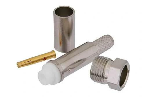
Cable-mount FME connector kit consisting of a threaded coupling shell, gold-plated center contact, dielectric connector body, and metal crimp ferrule.
The termination method is part-specific. Do not select solder or crimp from habit.
Use crimp only as a controlled system
A production crimp requires an approved combination of connector, cable, strip length, ferrule, die set, and center-contact process. A visually neat hex crimp can still have weak braid retention if the die is oversized.
Check the coaxial connector termination guide when defining tooling and inspection steps. Pull testing should be applied to the finished assembly, not only to a loose ferrule sample.
Keep solder heat and cable construction under control
Some FME parts use solder or mixed solder-and-crimp termination. Follow the connector drawing. Excess heat can deform the dielectric, wick solder into a stranded conductor, or create a stiff transition immediately behind the body.
For OEM production, a factory-terminated assembly is often safer when finished length, pull retention, and lot consistency matter more than field repair.
| Requirement | Field Crimp | Solder or Mixed | Factory Assembly |
| Field repair | Good with controlled tools | Possible with trained operator | Limited |
| Operator dependence | Medium to high | High | Lower |
| Finished-length control | Medium | Medium | High |
| Pull-test repeatability | Tool-dependent | Process-dependent | Easier to standardize |
| RF sampling | Usually separate | Usually separate | Can be included |
| Traceability | Limited unless recorded | Limited unless recorded | Lot control available |
| Best use | Service and low-volume work | Part-specific termination | OEM and repeat production |
Which mobile-antenna applications actually benefit from FME?
FME is most useful when the cable route and final equipment interface need to be treated separately.
A typical system is:
Vehicle antenna → thin coax → FME antenna connector → removable adapter → radio
This arrangement appears in mobile radios, GPS or GNSS receivers, cellular equipment, telemetry systems, marine electronics, and service installations. The radio may change from an SMA port to BNC or TNC, while the installed antenna cable remains in place.
| Application | Cable-Routing Need | FME Role | Final Interface |
| Vehicle antenna | Through trim or body opening | Compact cable end | Radio-specific adapter |
| GPS/GNSS receiver | Hidden miniature coax route | Serviceable transition | Often SMA or device-specific |
| Mobile radio | Vibration and equipment replacement | Modular antenna interface | BNC, TNC, Mini-UHF, or UHF |
| Marine installation | Confined route behind panels | Compact feedline connection | Equipment-dependent |
| Test or service setup | Temporary interface change | Adapter point | BNC or SMA equipment |
FME should not be treated as the permanent connector for every radio platform. Its value often comes from preserving the antenna cable route while allowing the final adapter to change.
How should FME-to-SMA or FME-to-BNC conversion be planned?
Adapter selection begins with four controlled fields:
FME gender + destination family + destination gender + impedance
“FME to SMA adapter” does not define a complete product. Neither does “SMA to FME adapter.” Passive RF adapters normally have no signal-direction requirement, so both phrases may describe the same family transition from opposite naming directions.
The SKU is determined by the physical end on each side.
Use FME to SMA for compact RF equipment
An FME to SMA adapter may connect a routed antenna cable to a compact receiver, modem, GNSS unit, telemetry device, or RF test port. Check:
- FME plug or jack
- SMA plug or jack
- Standard SMA interface
- 50 Ω impedance
- Available clearance
- Adapter length and leverage
- Required operating band
Use FME to BNC for BNC-based equipment
A BNC transition is common in radio and service equipment, but impedance must be stated. BNC is available in both 50 Ω and 75 Ω versions, and physical mating alone does not confirm electrical suitability.
An FME to BNC adapter should therefore identify the BNC impedance and gender in the purchasing description.
The current Amphenol RF FME adapter family includes transitions from FME to SMA, BNC, TNC, Mini-UHF, N-Type, and UHF. This range reflects FME’s role as a cable-side routing interface rather than a requirement that the destination equipment use an FME port.
What RF limits should be verified before an FME part is approved?
The connector may mate correctly and still be unsuitable for the operating band. FME is normally part of a 50 Ω RF path, but impedance alone does not qualify the assembly.
Treat 50 Ω as the starting point
Verify impedance across every element:
- Antenna
- Coax cable
- FME connector
- FME adapter
- Device port
- Test equipment, if used
A 75 Ω BNC adapter inserted into an otherwise 50 Ω path is an obvious mismatch. Less obvious errors come from cable substitutions, damaged dielectric, poorly installed center contacts, and adapters approved only by appearance.
A useful approval rule is:
Usable system frequency = the lowest verified frequency limit of any component in the complete RF path
The connector label cannot override a lower-rated cable, adapter, antenna, or device port.
Approve frequency by exact part number
There is no single maximum frequency that applies to all FME connectors. The TE Connectivity FME jack example used earlier is specified to 2 GHz. The Amphenol RF FME adapter range lists product-dependent ratings from approximately 1 to 4 GHz.
This variation is normal. Connector geometry, dielectric, adapter construction, cable termination, and test criteria differ between products. A generic marketplace claim such as “FME connector, 2.4 GHz” should not replace a drawing or datasheet.
Measure the finished path near the product limit
Continuity confirms that a conductive path exists. It does not measure insertion loss, impedance discontinuity, or reflections.
For RF-critical assemblies, sweep the finished link at the actual operating band and record:
- S21 or insertion loss
- S11 at the input
- S22 when both ends matter
- Return loss or VSWR
- Free-state cable condition
- Installed bend condition
- Results before and after re-mating
Build the purchase specification around the complete cable path
“Need an FME connector” leaves most of the engineering decisions open. It does not define gender, cable, termination, adapter, frequency, or finished length.
A usable BOM description should look closer to this:
FME jack, center socket, 50 Ω, straight cable-mount configuration, for approved RG316 cable, crimp termination, 500 mm finished length, destination interface SMA plug, operating range DC–2 GHz, continuity and isolation tested, sample return-loss report required.
The values will change by project. The structure should not.
Define the cable and mechanical requirements
Include:
- Exact cable P/N or approved equivalent
- Jacket outside diameter
- Finished length and tolerance
- Minimum installed bend radius
- Strain-relief requirement
- Pull-force requirement
- Routing environment
- Temperature range
- Vibration or moisture exposure
- Packaging and identification label
If cable loss may control the design, use the 50 ohm coaxial cable selection guide before locking the connector and finished length.
Attach the mating drawing and installed-path photograph to the RFQ. That small step prevents the purchasing description from being separated from the geometry it was supposed to control.
Qualify the first article before releasing volume production
The first article should be inspected as a complete assembly. Testing a loose connector, an unterminated cable, or an adapter by itself cannot qualify the production cable path.
Inspect interface identity and workmanship first
Check:
- FME interface and gender
- Center-contact position
- Thread condition
- Cable P/N and marking
- Finished length
- Ferrule deformation
- Jacket cuts or heat damage
- Connector rotation
- Strain relief
- Adapter identity
Use an approved mating part or “golden mate” for the fit check. Do not force a new connector into a worn or unidentified port.
Separate mating retention from cable retention
These are different failure modes:
- Mating retention: the FME connection remains coupled during vibration or movement.
- Cable retention: the coax cannot pull out or rotate inside the terminated connector.
A tight threaded interface does not prove that the ferrule has captured the braid. Likewise, a strong cable crimp does not prove that the mating geometry or center-contact position is correct.
Run electrical tests after mechanical inspection
At minimum, production assemblies should be checked for:
- Center-conductor continuity
- Shield continuity
- No center-to-shield short
For higher-risk applications, add VNA sampling, re-mating checks, installed-bend testing, and lot-based pull testing.
| Test | Method | Acceptance | Evidence |
| Interface identity | Visual/drawing | Exact match | Photograph |
| Cable match | Marking/dimension | Approved P/N | Inspection record |
| Mating fit | Golden mate | Full engagement | Record |
| Cable pull | Controlled fixture | Project limit | Test result |
| Connector rotation | Torque or hand check | Project limit | Record |
| Continuity | Electrical tester | Pass | Test log |
| Isolation | Electrical tester | Pass | Test log |
| S21 | VNA | RFQ limit | Report |
| Return loss | VNA | RFQ limit | Report |
Diagnose failures that appear only after the cable is installed
A cable can pass on an open bench and fail after the vehicle trim is installed. The difference is usually mechanical state.
Suspect routing stress when the bench test passes
Inspect for:
- Bend radius tighter than the cable allows
- Coax trapped beneath trim or a mounting bracket
- Excess tension from a short service loop
- Unsupported adapter weight
- Radio movement pulling on the cable
- FME thread partially loosened
- Cable rotation inside the ferrule
- Moisture entering an unsealed transition
Do not immediately replace every component. Change one interface at a time so the fault location remains visible.
A practical diagnostic order is:
- Antenna
- Routed coax
- FME cable end
- FME adapter
- Device port
If performance changes only after clipping or trim installation, replacing the adapter may not solve the problem. The cable route, support point, or bend condition should be corrected first.
FAQ
How can I identify an FME connector if the cable has no label?
Photograph the mating face and side profile, then record the thread, body diameter, center contact, dielectric, and existing mating adapter. Check the equipment manual or antenna drawing if available. A small threaded body on a vehicle antenna cable is a useful clue, but it is not enough to confirm FME without checking the complete geometry.
Can the same FME connector terminate both RG174 and RG316?
Only when the exact connector part number is approved for both cables. Some FME designs list compatibility with RG174A, RG188A, and RG316, but this does not apply to every FME coax connector. Compare jacket, braid, dielectric, and center-conductor dimensions, then verify the ferrule, contact, strip dimensions, and pull retention.
Why is FME useful in vehicle antenna installations?
Its compact cable-side form can pass through openings that would not accept a larger BNC, TNC, N-Type, or UHF connector. The antenna cable can be routed first, followed by an equipment-specific adapter. This also allows the radio interface to change later without removing the complete coax route from behind trim or vehicle panels.
Can “FME to SMA” and “SMA to FME” describe the same adapter?
They can describe the same connector-family transition because a passive RF adapter normally has no signal direction. The actual product is defined by the FME gender and SMA gender on the two physical ends. Write both ends into the specification instead of approving an adapter from the word order in its title.
Does every FME connector have the same maximum frequency?
No. Frequency capability varies by connector and adapter part number. Current manufacturer examples include FME products with different upper limits, so a family-level frequency claim should not be applied to every part. Verify the connector, cable, adapter, antenna, and device port, then test the finished path when operation is close to any component limit.
Should an FME cable be tested again after vehicle installation?
For a first article or RF-critical installation, yes. Cable bending, trim pressure, insufficient service loop, adapter leverage, and connector movement can create faults that are absent during straight bench testing. Compare continuity and RF behavior before routing, after clipping, and after the trim or equipment is fully installed.
An FME connector is useful because it separates a compact antenna-cable route from the final equipment interface. That advantage disappears when gender, coax dimensions, adapter geometry, and installed stress are left unspecified.
For a new or custom assembly, send the mating drawings, cable P/N, finished length, destination interface, operating frequency, installed routing condition, and required inspection data before production. Those details make it possible to confirm the complete path instead of approving the FME end in isolation.
