
A coax adapter can screw into both ports perfectly and still be the wrong part.
That problem appears more often than buyers expect. A technician identifies one side as SMA, sees BNC on the other device, orders an SMA-to-BNC adapter, and assumes the job is finished. The adapter arrives, both ends mate, but the center contact is wrong, the impedance does not match the RF path, or the body geometry puts excessive load on a small PCB-mounted connector.
The safer way to select a coax adapter is to work backward from the two installed ports. Do not start with a supplier listing. Record exactly what is already on the equipment, determine what each port must mate with, and only then build the adapter specification.
That small change in sequence eliminates a surprising number of sourcing mistakes.
How do you translate two installed ports into the correct coax adapter?
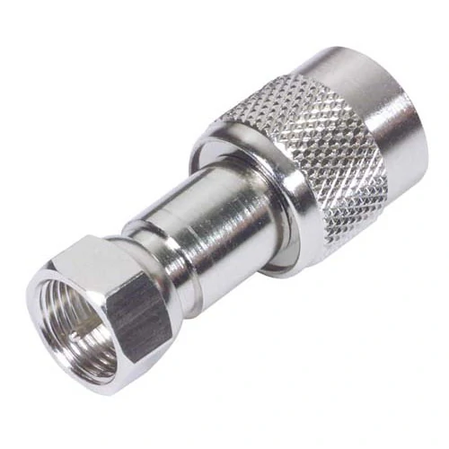
Straight cross-series RF coax adapter used to resolve connector-family and gender compatibility between threaded and bayonet-style equipment ports.
A supplier may list hundreds of RF adapters with names that look almost identical. Searching those listings before identifying the equipment ports usually creates unnecessary confusion.
Start with the hardware.
For each side of the connection, record the connector family, equipment-side gender, center-contact structure, polarity, nominal impedance, required operating frequency, and mounting condition.
A practical record might look like this:
| Check item | Port A | Port B |
| Equipment | Radio module | Test cable |
| Connector family | SMA | BNC |
| Equipment gender | Female | Male |
| Center contact | Socket | Pin |
| Polarity | Standard | Standard |
| Impedance | 50 Ω | 50 Ω |
| Required frequency | Application-specific | Application-specific |
| Mounting | Panel | Cable |
The adapter is then derived from these two ports.
Start from the equipment ports instead of the product listing
Suppose Device A has an SMA female port.
The adapter cannot simply be described as “SMA.” Its SMA side must provide the mating interface required by that installed port. In this case, the adapter side needs to be SMA male.
If Device B has a BNC male cable connector, the other end of the adapter must provide the corresponding BNC female interface.
The useful selection logic is therefore:
Installed Port A + Installed Port B → Required Adapter End A + Required Adapter End B
This is more reliable than searching for something that visually resembles an “SMA BNC adapter.”
The same method applies to N-Type, TNC, SMB, MCX, MMCX, and other RF connector families.
Reverse each installed port into its required mating interface
This “reverse the port” step is simple, but it should be written down rather than handled from memory.
If the installed port is:
- SMA female → adapter side requires SMA male
- SMA male → adapter side requires SMA female
- BNC female → adapter side requires BNC male
- N female → adapter side requires N male
That still does not complete the specification.
For interfaces where standard and reverse polarity versions exist, the center contact must be checked independently from the outer coupling structure. Two connectors can have similar threads and still be electrically or mechanically incompatible.
This is why a product photo alone is weak purchasing evidence.
The existing TEJTE guide on coaxial cable connectors is useful when the connector family itself has not yet been identified. Once both installed interfaces are known, adapter selection should move to the mating-interface method rather than repeating basic connector identification.
Treat signal direction as irrelevant to passive adapter naming
Another source of confusion is naming order.
A supplier may describe the same general transition as:
SMA to BNC
while another supplier writes:
BNC to SMA
For an ordinary passive straight-through RF adapter, that wording does not establish a fixed RF input and output direction. What determines the actual SKU is the physical configuration at both ends.
For procurement, “SMA to BNC adapter” is therefore incomplete.
A specification such as:
SMA Male to BNC Female RFAdapter, 50 Ω, Straight
is much harder to misinterpret.
Complete a two-port decoder before searching suppliers
For repeat orders, OEM sourcing, or projects with several connector combinations, a simple port decoder is worth keeping with the RFQ.
Coax Adapter Port Decoder
Do not approve the adapter until both “Required adapter end” fields can be filled without guessing.
If one field is uncertain, ask for a clear interface photo or mechanical drawing before ordering. That is cheaper than discovering the ambiguity during incoming inspection.
Which mismatches can a coax adapter fix—and which ones cannot?
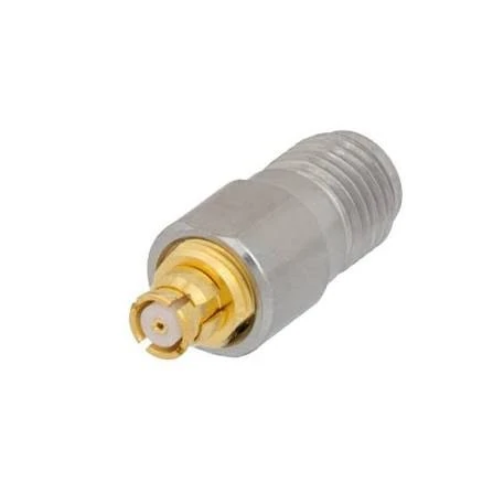
Miniature cross-series coax adapter designed to connect threaded and snap-on RF interfaces in compact wireless modules, test equipment, and RF assemblies.
A passive RF adapter is useful, but it is not a universal conversion device.
Its job is mainly to create a compatible RF interconnection between two physical interfaces. It can solve many connector-family and gender problems. It cannot automatically correct every electrical incompatibility behind those connectors.
That boundary matters because a system can be mechanically connected while the RF path remains wrong.
Use an adapter for mechanical interface conversion
A coax adapter is a reasonable solution when the actual problem is one of these:
- different RF connector families
- same connector family but incompatible gender
- standard-to-reverse-polarity transition using the correct dedicated adapter
- straight-to-right-angle geometry
- panel or bulkhead transition
- RF test fixture interface conversion
For example, moving between an SMA interface on compact equipment and an N-Type interface on a larger RF cable is a normal adapter task, assuming impedance, frequency, power, and mechanical loading are also acceptable.
The adapter bridges the interface. It does not change the underlying signal format.
Do not use a passive adapter to convert signal formats
A coaxial connector should not be confused with the signal carried through it.
A passive RF adapter cannot perform jobs such as:
- analog-to-digital conversion
- HDMI conversion
- Ethernet protocol conversion
- active frequency translation
- modulation conversion
Those functions require an appropriate active converter, transceiver, modem, mixer, or other signal-processing hardware.
This distinction becomes important during sourcing because the word “adapter” is used for many unrelated products. An RF connector adapter and an HDMI converter may both be called adapters, but they solve completely different problems.
Treat impedance mismatch as an electrical problem, not a gender problem
Impedance deserves its own check.
Consider this path:
50 Ω device → 75 Ω adapter/interface → 50 Ω cable
Everything may connect mechanically. That does not make it a correct RF path.
The impedance discontinuity can increase reflections and degrade return loss. The actual effect depends on frequency, system length, transition geometry, and the rest of the RF chain, so it should not be reduced to a simple “it fits, therefore it works” decision.
This is especially relevant with connector families that may exist in more than one impedance version.
A useful purchasing rule is:
Mechanical compatibility allows assembly. Electrical compatibility determines whether that assembly belongs in the RF system.
The boundary can be summarized like this:
| Problem | Passive coax adapter? | Better approach |
| Gender mismatch | Yes | Correct adapter |
| Connector-family mismatch | Yes | Cross-series adapter |
| Standard/RP mismatch | Yes, with correct configuration | Polarity-specific adapter |
| 50 Ω / 75 Ω mismatch | Usually not a matching solution | Correct impedance path or matching network |
| Analog-to-digital conversion | No | Active converter |
| Frequency translation | No | Mixer / converter |
| Heavy cable stressing a small port | May be mechanically poor | Flexible RF jumper |
| Misaligned fixed ports | May be mechanically poor | Cable assembly |
The last two rows are easy to overlook. An adapter may be electrically correct but still be the wrong mechanical architecture.
A rigid adapter attached to a heavy feeder cable can put leverage directly into a PCB-mounted SMA or other compact connector. Two fixed ports at different heights can create a similar problem even if the interfaces are technically correct.
That is where adapter selection stops being a connector question and becomes a system-integration decision.
The next step is to separate connector family, gender, polarity, and impedance into independent compatibility checks before the SKU is approved.
How do you separate connector family, gender, polarity, and impedance?
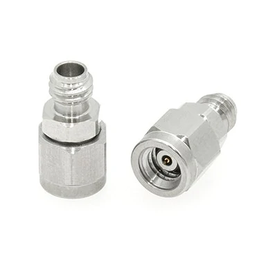
Pair of compact RF coax adapters used for connector-interface conversion in wireless equipment, test fixtures, antenna systems, and other space-limited RF assemblies.
A connector that threads on correctly has passed only the first part of the compatibility check.
Before approving a coax adapter for a BOM, treat connector family, gender and polarity, impedance, and RF rating as separate gates. Combining them into one visual judgment is where many sourcing errors begin.
Identify the connector family before gender
“Male” and “female” do not describe an RF interface completely.
An SMA male, BNC male, TNC male, and N-Type male are all male connectors, but they cannot mate with one another. Connector family comes first.
A useful inspection sequence is:
- Identify the connector family.
- Confirm the outer coupling structure.
- Check the center contact.
- Confirm standard or reverse polarity.
- Verify impedance.
- Check the required frequency and power conditions.
This sequence is particularly useful when photos come from customers or field technicians. A close-up image may make the center pin obvious while hiding thread dimensions or the body size that distinguishes one family from another.
Verify the center contact separately from the outer coupling
Polarity mistakes deserve extra attention.
Standard SMA and RP-SMA are a good example. The outer threaded coupling can look familiar while the center contact differs. The same risk exists with standard and reverse-polarity versions of some TNC interfaces.
Do not approve a part because the thread “looks right.”
For ambiguous RF interfaces, ask the supplier or customer for:
- a front-facing connector photo
- a side view showing the coupling structure
- center-contact detail
- drawing or dimensional reference when available
This matters most when a low-resolution product image is being used to identify small connectors.
Keep 50 Ω and 75 Ω versions in separate decision paths
RF systems should also be checked by impedance rather than connector appearance alone.
Many RF test, antenna, radio, and wireless systems use 50 Ω paths. Video and CATV systems commonly use 75 Ω paths. Some connector families, including BNC, can exist in more than one impedance version.
That creates a common sourcing trap: the adapter mates mechanically, continuity passes, and the wrong impedance is discovered only when return loss is measured.
For a 50-ohm RF chain, the safer purchasing assumption is not “BNC is BNC.” It is:
Port impedance → adapter impedance → cable impedance → load impedance
Those values should remain consistent unless the system intentionally includes an impedance-matching section.
TEJTE’s 50 Ohm Coaxial Cable Guide covers the cable side in more detail. For adapter selection, the important point is simply to keep impedance continuity visible in the approval record.
Build a four-layer compatibility test
A practical approval gate can be reduced to four checks:
| Compatibility layer | Question | Result if wrong |
| Family match | Are both adapter ends the correct connector families? | FAIL |
| Gender / polarity | Does each end mate with the installed port, including center contact? | FAIL |
| Impedance | Does the adapter belong in the intended RF impedance path? | FAIL / redesign |
| Frequency / power | Is the adapter suitable for the application limits? | REVIEW or FAIL |
When should a direct adapter be replaced by a jumper or cable assembly?
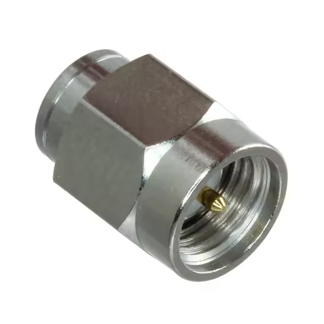
Close-up product view of a straight coax adapter, highlighting the threaded interface, center contact, and body geometry used during mechanical compatibility inspection.
A direct coax adapter is attractive because it is small, inexpensive, and eliminates cable length. That does not automatically make it the better mechanical solution.
The physical load on the equipment port matters.
Keep a rigid adapter when both ports are aligned and supported
A rigid adapter works well when:
- both interfaces line up naturally
- neither side moves
- the connected cable is lightweight
- the equipment port is mechanically supported
- the assembly will not be exposed to significant vibration
- the adapter does not create excessive leverage
Typical examples include short bench transitions and fixed equipment connections where the adapter is not supporting a heavy feeder cable.
Switch to a flexible jumper when alignment is imperfect
A short RF jumper becomes more attractive when:
- the ports are offset
- mounting heights differ
- one interface is PCB-mounted
- the attached cable is stiff or heavy
- equipment will be moved regularly
- vibration is expected
- several rigid adapters would otherwise be stacked
The electrical path may become slightly longer, but the mechanical benefit can be substantial.
A flexible jumper can isolate movement instead of transferring it directly into the equipment connector.
The TEJTE SMA Adapter Selection & Ordering Guide makes the same practical distinction when adapter stacking or enclosure space becomes a problem: another rigid transition is not always the best answer.
Compare adapter and jumper by total system cost
Do not compare only the adapter price against the jumper price.
Include:
- component cost
- port repair risk
- cable replacement cost
- assembly labor
- recalibration time
- field-service effort
- downtime
- repeatability after re-mating
A $5 mechanical shortcut can become expensive if it damages an instrument port or requires repeated field adjustment.
Use a rigid-or-flexible decision tree
A simple internal screening method is to count mechanical risk flags:
- Are the ports naturally aligned?
- Will either side move?
- Is one connector mounted directly to a PCB?
- Is the attached cable heavy or stiff?
- Are two or more adapters already stacked?
- Is there effective strain relief?
A practical engineering screen can be:
- 0–1 risk flags: rigid adapter is usually reasonable
- 2–3 risk flags: review mechanical support
- 4 or more: consider a flexible jumper or purpose-built cable assembly
This is not an international standard. It is a purchasing and engineering screening tool intended to make mechanical risk visible before release.
How much loss and mismatch can one adapter add?
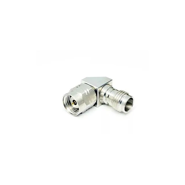
Compact 90-degree coax adapter designed to change the cable exit direction, reduce axial clearance requirements, and simplify RF connections inside crowded equipment.
Avoid universal statements such as:
“Every coax adapter adds 0.1 dB.”
That number may be reasonable in one test condition and wrong in another.
Added loss depends on the connector families, operating frequency, transition geometry, materials, manufacturing tolerance, mating condition, and the baseline path used for comparison.
Measure against a baseline rather than quoting a generic dB value
The cleaner method is to test the path without the adapter, then insert the adapter and repeat the same measurement.
Use:
Adapter Added Loss(f) = IL with adapter(f) − IL baseline(f)
Keep the cable, calibration plane, frequency sweep, and mating condition as consistent as possible.
IEC 61169-1-2:2019 specifically covers insertion-loss measurement methods applicable to RF connector adapters, which makes this baseline-style testing approach more useful than quoting an unsourced generic loss value.
Track return loss as well as insertion loss
Low insertion loss does not guarantee a clean impedance transition.
An adapter may transmit most of the power while still creating a reflection problem at a particular frequency.
For RF-critical applications, review at least:
- S21
- S11
- S22
- worst-case frequency point
This becomes more important near the upper operating band, where small dimensional changes may have a larger effect on RF behavior.
The acceptance limit should come from the real system requirement rather than from a universal adapter number.
A production antenna system, a laboratory calibration path, and a general radio connection may all tolerate different levels of mismatch.
Build a one-page compatibility matrix before approving the SKU
If an adapter will be reordered, customized, or used in production, keep the decision on one record.
Do not leave interface details scattered across chat screenshots, purchase notes, and supplier product titles.
Put every compatibility field on one record
Use only three approval states:
PASS — directly compatible REVIEW — drawing, measurement, or application test still required FAIL — wrong configuration
For ambiguous interfaces such as RP-SMA, MCX, MMCX, SMB, or small proprietary-looking RF ports, attach a photo or drawing to the record.
That step becomes especially valuable months later when the same adapter is reordered by someone who was not involved in the first sourcing decision.
The next question is no longer whether the adapter fits. It is whether the body style, mounting method, adapter count, and inspection plan will remain stable once the part moves from a single bench sample into repeated production use.
How should straight, right-angle, bulkhead, and flange bodies be chosen?
Once the electrical interfaces are confirmed, body geometry becomes the next source of mistakes.
Two adapters can have exactly the same connector family, gender, impedance, and frequency requirement while behaving very differently after installation.
Use straight adapters when axial clearance and load are controlled
A straight adapter is usually the simplest option when the two mating directions already line up.
It offers:
- short physical length
- straightforward inspection
- easy tool access
- fewer mechanical complications
- a direct signal transition
That simplicity is useful in bench setups, test fixtures, and fixed equipment where nothing is forcing the cable to bend immediately behind the connector.
The weakness is leverage.
A long or heavy cable hanging from a straight adapter can transfer force directly into the equipment port.
Choose right-angle only when it solves a real enclosure constraint
A right-angle adapter can solve an enclosure problem, but it should not be added only because it looks more convenient.
Check:
- available cable exit direction
- access for tightening tools
- adjacent connector spacing
- enclosure wall clearance
- cable bend radius
- leverage on the equipment port
In crowded equipment, a right-angle body may reduce axial space while creating interference in another direction.
Move the mating point to a bulkhead when the enclosure should carry the load
A bulkhead adapter is useful when the connection should be supported by a panel rather than by a PCB or internal cable.
Typical applications include:
- external antenna ports
- service panels
- frequently mated interfaces
- equipment using heavier external cables
- enclosure feed-through connections
Panel thickness and nut engagement should be included in the drawing or RFQ. A bulkhead part that fits the connector electrically can still be unusable if the threaded mounting section is too short.
Use flange mounting when rotation and repeatability matter
Flange-mounted adapters add mechanical control.
Depending on the design, the mounting may use:
- two-hole flange
- four-hole flange
- anti-rotation feature
- fixed mounting pattern
They make sense when repeated installation position matters or when the assembly must resist rotation better than a simple bulkhead nut.
A practical comparison is:
| Requirement | Straight | Right-angle | Bulkhead | Flange |
| Short electrical path | Best | Good | Good | Good |
| Tight axial space | Poor | Good | Depends | Depends |
| Panel mounting | No | Rare | Yes | Yes |
| Anti-rotation control | Low | Medium | Medium | High |
| Heavy cable support | Poor | Poor | Better | Best |
| Service accessibility | High | Medium | High | Medium |
The body style should therefore be specified in the BOM rather than left to supplier interpretation.
How do you prevent adapter stacks from creating mechanical failure?
Adapter stacks usually begin innocently.
One adapter solves the connector family. Another solves gender. A third changes direction.
The result may look like:
SMA → SMA barrel → SMA-to-N → N right-angle
Each component may be correct individually, but the assembly has accumulated several interfaces.
Treat each added interface as another uncertainty source
Every additional adapter can add another contribution to:
- insertion loss
- return-loss variation
- thread tolerance
- contact wear
- connection repeatability
- calibration uncertainty
- loose-interface risk
There is also a mechanical penalty because the stack becomes longer.
That extra length increases leverage on the original equipment port.
Calculate an adapter-stack risk score
For internal screening, a simple risk index can be used:
Rstack = Nadapter + Nunsupported + Nright-angle + Nimpedance-transition
A practical interpretation is:
- 0–2: simple setup
- 3–4: engineering review
- 5 or more: consider redesign
This is not an IEC requirement or industry standard. It is an internal engineering screening tool.
Its purpose is to trigger a review before a convenient bench workaround becomes a production design.
Replace the chain with one purpose-built cable when possible
If the connection has become:
SMA → N → BNC
compare that arrangement with a purpose-built:
SMA-to-BNC cable assembly
The cable version may reduce the number of mating interfaces and isolate mechanical movement at the same time.
The better answer is not always “fewer components,” but a long adapter stack deserves justification rather than automatic approval.
Which checks belong in first-article and incoming inspection?
Do not begin adapter inspection with the VNA.
Confirm the hardware first.
Inspect mechanical compatibility before RF testing
Initial checks should include:
- connector family
- gender
- center contact
- polarity
- thread condition
- center-contact alignment
- plating condition
- body damage
A known-good mating connector or inspection fixture is preferable to repeatedly trying an uncertain adapter directly on an expensive instrument port.
Separate first-article qualification from routine IQC
First-article qualification should be deeper because the design itself is being approved.
It may include:
- critical dimensions
- full frequency sweep
- mechanical mating
- repeated mating
- installed-state test
- S21
- S11 / S22
- visual condition
Routine incoming inspection can then focus on the characteristics most likely to vary by lot.
For example:
| Inspection item | Method | Typical scope | Failure action |
| Interface identity | Visual | 100% | Quarantine |
| Thread/contact condition | Visual | 100% | Sort |
| Mechanical mating | Golden fixture | Sample | Hold lot |
| Continuity | Electrical | Inspection plan | Reject / investigate |
| S21 | VNA | Risk-based | Expand sample |
| S11 / S22 | VNA | Risk-based | Investigate |
| Re-mating repeatability | Qualification | First article | Review design |
Convert field observations into a supplier-ready adapter RFQ
“Need SMA BNC adapter” is not an RFQ.
It leaves too many decisions to the supplier.
A more useful description is:
SMA Male to BNC Female RFAdapter, 50 Ω, Straight
Then add the operating requirements.
Write both interfaces completely
For each end, define:
- connector family
- male/female configuration
- center contact
- standard or reverse polarity
Do not rely only on a supplier SKU if the part may be sourced from more than one factory.
Add electrical limits
Include where relevant:
- impedance
- frequency range
- maximum insertion-loss requirement
- return loss or VSWR requirement
- power requirement
Avoid inventing tight limits simply because a number looks attractive. The limit should come from the real application or qualification plan.
Add mechanical and environmental limits
Depending on the project, also specify:
- straight or right-angle
- bulkhead or flange
- panel thickness
- thread details
- waterproof requirement
- expected mating cycles
- body material
- contact plating
- environmental conditions
A reusable RFQ record can look like this:
A buyer using this format gives the supplier far less room to make a technically reasonable but commercially wrong substitution.
How should you diagnose an adapter that fits but performs poorly?
Do not replace the radio, VNA, or antenna first.
Isolate the adapter path.
Start by proving the mechanical interface is correct
Check whether the adapter is:
- fully seated
- correctly polarized
- free from thread damage
- aligned at the center contact
- properly tightened
- mechanically stable
A poor connection can appear as an RF problem even when the adapter design itself is correct.
Isolate impedance mismatch from adapter defect
Change one variable at a time.
A useful substitution sequence is:
- known-good cable
- known-good adapter
- known-good load
- same frequency range and test setup
Changing the cable, adapter, and load together may restore the measurement, but it does not identify the failed component.
Compare static and movement-sensitive results
A revealing symptom is:
Static measurement passes, but touching the adapter changes S21.
That may indicate:
- contact wear
- port loading
- loose coupling
- damaged connector
- unstable internal contact
- excessive mechanical leverage
If several adapters are already stacked, simplify the chain before blaming expensive equipment.
FAQ
How can I identify the exact coax adapter when I only know the two equipment ports?
Record each installed port separately: connector family, gender, center contact, polarity, impedance, and required operating frequency. Then determine the mating interface needed for each port. For example, an SMA female equipment port requires the corresponding SMA male adapter interface. Combine the two required mating interfaces into the final adapter specification. Do not select the part from a product photo or from a generic description such as “SMA BNC adapter.”
Can a passive coax adapter convert a 50-ohm port to a 75-ohm system?
A passive adapter may make the two interfaces physically connect, but an ordinary straight-through adapter is not automatically an impedance-matching network. Mixing 50 Ω and 75 Ω sections can introduce an impedance discontinuity and increase reflection. The impact depends on the operating frequency and complete RF path. For controlled RF applications, keep the device, adapter, cable, and termination impedance consistent or use an intentionally designed matching solution.
How many coax adapters can I stack?
There is no universal maximum number. The problem is cumulative risk rather than a fixed count. Each added interface can contribute insertion loss, mismatch, contact variation, mechanical leverage, and another point that may loosen or wear. Once two or three different adapters are needed to build one connection, compare the stack with a purpose-built RF cable assembly. A longer chain should have a clear engineering reason rather than being used only because the parts are available.
Why can a coax adapter mate correctly but still fail an RF test?
Mechanical mating proves only that the physical interfaces can engage. It does not confirm impedance, internal transition geometry, manufacturing tolerance, or high-frequency performance. An adapter can pass continuity and still show poor S21 or return loss near the application band. That is why RF-critical adapters should be evaluated against the intended frequency range rather than approved only from visual inspection and continuity testing.
When is a short RF jumper better than a rigid coax adapter?
A flexible jumper is often preferable when the two ports are offset, one connector is PCB-mounted, the external cable is heavy, the equipment will move, or several adapters would otherwise be stacked. The jumper adds cable length, but it can isolate mechanical force and reduce leverage on the equipment connector. This is especially useful when a rigid adapter would force the cable into a tight bend immediately after the port.
Should incoming coax adapters be tested for both insertion loss and return loss?
For RF-critical applications, checking both provides a more complete picture. Insertion loss shows how much transmission loss is added to the path, while return loss or S11/S22 helps reveal impedance discontinuities. A part may have low transmission loss but still create an unacceptable reflection at certain frequencies. Routine inspection can be risk-based, while first-article qualification normally deserves a broader frequency sweep and more complete RF evaluation.
Does “SMA to BNC” mean the RF signal can only travel from SMA toward BNC?
No. For a normal passive RF adapter, “SMA to BNC” generally describes the two connector families rather than a fixed input and output direction. The naming order may even change between suppliers. Procurement should therefore focus on the complete interfaces at both ends: family, gender, polarity, impedance, frequency capability, and body style. Those details determine whether the part is correct, not the order of the words in the listing.
Final practical note
The safest way to buy a coax adapter is to stop treating it as a two-word connector description.
Start with the two installed ports. Reverse each into the mating interface the adapter must provide. Then check family, gender and polarity, impedance, frequency and power, body geometry, mechanical loading, and inspection requirements.
If that process produces a chain of several adapters, reconsider the architecture.
For supplier communication, send both interface definitions, operating frequency, impedance, body style, mounting requirement, RF acceptance limits, and a drawing or clear connector photos where identification is uncertain.
That information is usually more valuable than sending a product screenshot and asking whether it “should fit.”
