
A right-angle connector can solve a packaging problem and create a different one at the same time.
A common case looks simple in CAD: the PCB has an SMB port, the enclosure is shallow, and a right angle SMB connector appears to save height. The first sample even fits. Then the cable is added, the lid is closed, and the elbow points directly toward a shield can or enclosure wall. Production has to bend the coax immediately after the ferrule just to make the assembly fit.
That is not really a connector-selection problem. It is an installed-envelope problem.
For a 90-degree SMB cable end, the front mating interface is only one part of the specification. Cable exit direction, coax diameter, ferrule size, neighboring components, strain relief, and the first cable support point can determine whether the assembly actually works inside the equipment.
Does the enclosure actually need a 90-degree SMB exit?
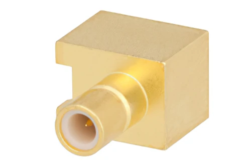
Gold-plated right angle SMB connector with a compact rectangular body for PCB-mounted RF applications where board clearance and connector orientation must be controlled
A shallow enclosure does not automatically require an elbow connector.
The useful comparison is not simply straight connector versus 90-degree connector. Compare the space occupied by the finished cable assembly after routing.
A straight SMB cable connector may project farther away from the PCB, but the cable can sometimes leave that connector along an open path. A right-angle version reduces axial projection while moving the ferrule and coax sideways. If that side space is already occupied by a wall, battery, shielding cover, screw boss, or another RF port, the elbow can make assembly harder rather than easier.
Compare axial depth with side-exit space
Start with the mechanical envelope around the mated interface.
Record at least:
- PCB-to-lid distance
- connector body height
- elbow body width
- cable outside diameter
- ferrule dimensions
- side-wall clearance
- neighboring component height
- intended cable routing direction
- first cable clamp or tie point
The last two items are easy to overlook. A connector can fit perfectly by itself while the coax has nowhere practical to go.
Identify the bend a straight connector would force into the cable
The strongest reason to use a 90 degree SMB connector is often not connector height. It is eliminating an immediate cable bend.
With a straight cable exit, the real occupied depth is closer to:
connector length + protected straight section + required cable bend
If the coax must turn immediately after termination, forcing the bend closer to the ferrule may transfer stress into the braid, center conductor, termination, or PCB-mounted mating connector.
An elbow changes that direction inside the connector geometry. That can make routing cleaner, but it does not remove the need to manage strain in the cable behind it.
A practical comparison looks like this:
| Design factor | Straight SMB | Right-angle SMB |
| Axial clearance | Usually requires more depth | Usually reduces axial projection |
| Lateral clearance | Often lower | Requires side-exit space |
| Immediate cable bend | May be required | Often reduced |
| Exit-direction control | Less sensitive | More important |
| Nearby-component interference | Depends on forward routing | Depends heavily on elbow direction |
| Strain-relief planning | Required | Still required |
| Assembly access | Often straightforward | Tool access may be more restricted |
| Best fit | Open axial routing | Shallow layouts with usable side space |
The table is a screening tool, not a substitute for the supplier drawing. Actual dimensions vary by connector construction and cable termination.
Reject the elbow when it creates a worse collision
There are several situations where a straight connector should remain on the BOM even in a compact device.
One is an elbow that exits directly toward a shielding can. Another is a connector body that fits below the lid but places its ferrule against the enclosure wall. Service access also matters: a low-profile design has little value if technicians cannot remove the connector without first dismantling the surrounding hardware.
The better design question is therefore:
Which version leaves the cable in a natural, supportable position after the enclosure is fully assembled?
That answer is more useful than asking which connector looks shorter on a product drawing.
Which mating interface belongs at the elbow?
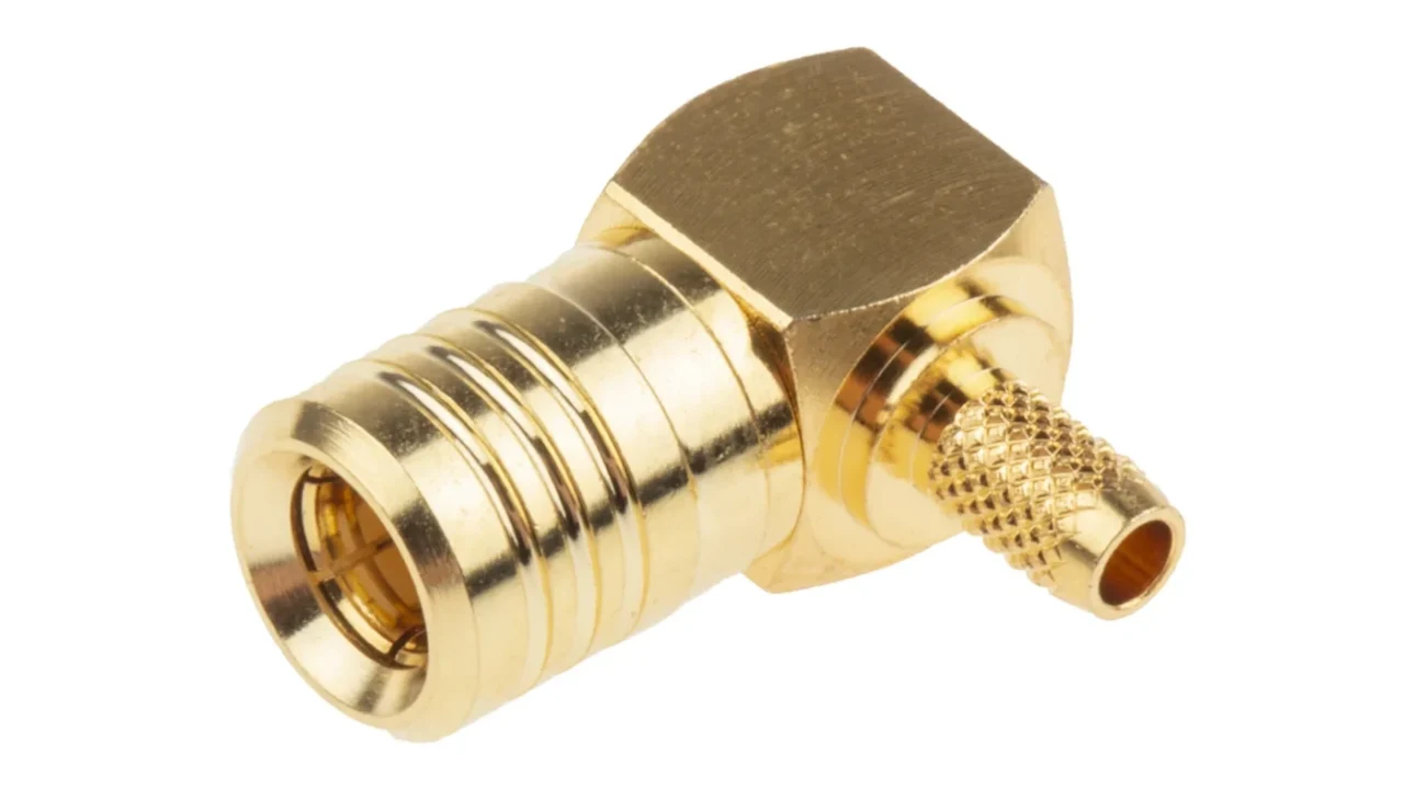
Once the 90-degree geometry makes sense mechanically, confirm the SMB mating interface before selecting the rear body.
Do not reverse that order.
A purchasing description such as “SMB right angle female connector” may sound complete, but it still leaves room for error if the equipment-side interface, center contact, cable termination, and supplier terminology have not been checked against a drawing.
Confirm plug and jack before selecting body geometry
The approval record should identify both sides of the connection:
- SMB interface designation
- plug or jack
- center pin or socket
- equipment-side mating connector
- cable-side connector
- nominal impedance
- supplier drawing or approved sample
IEC 61169-10:2024 covers the 50 Ω SMB snap-on connector series and defines items such as mating-face dimensions, gauging, tests, and inspection requirements. The IEC publication states an operating frequency of up to 4 GHz for the standardized series.
That standard reference is useful for the SMB interface itself. It does not mean every commercial elbow, cable termination, or finished assembly will have identical RF behavior.
Separate male/female selection from straight/right-angle selection
These are two different decisions.
First determine what must mate with the equipment. Then decide whether the cable-side body should be straight or 90 degrees.
A useful specification sequence is:
Equipment interface → mating SMB interface → impedance → body geometry → cable → termination → exit orientation
This prevents a common sourcing mistake: finding a mechanically attractive elbow first and then trying to make its interface fit the existing device.
For production sourcing, keep a simple verification card with the RFQ:
| Verification field | Equipment side | Cable connector |
| Connector family | SMB | SMB |
| Plug / jack | Confirm | Confirm |
| Center contact | Confirm | Confirm |
| Nominal impedance | Confirm | Confirm |
| Body direction | Fixed by equipment | Straight / 90° |
| Cable exit direction | — | Define from datum |
| Drawing reference | Record P/N | Record P/N |
| Sample/photo confirmation | Recommended | Recommended |
A photograph can help communication, but it should not replace the drawing.
Similar-looking miniature RF connectors should also stay out of the approval path. The project drawing should explicitly identify SMB rather than relying on appearance, especially when multiple snap-on connector families are used in the same equipment.
At this stage, the question is no longer simply “male or female?” The useful purchasing question is:
Which exact SMB mating interface is required, and where must the cable leave that interface after installation?
The next design step is to turn that answer into actual board clearance, lid clearance, cable dimensions, and tolerance limits.
How much board and lid clearance should the elbow reserve?
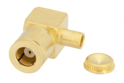
Right angle SMB connector featuring a compact 90-degree construction and removable protective cap, designed to protect the RF interface before installation or during storage.
A right-angle SMB can fit in the CAD model and still become a production problem once ferrules, heat shrink, cable tolerance, and enclosure tolerance are added.
Do not dimension only the metal elbow body. The installed height should include the complete stack from the PCB mating point to the highest or widest part of the finished assembly.
That normally means checking:
- mated PCB connector height
- right-angle connector body
- ferrule
- heat shrink or boot
- cable OD
- assembly tolerance
- PCB placement tolerance
- lid or chassis tolerance
Define a keep-out zone around the finished assembly
For SMB right angle connector dimensions, supplier drawings are the starting point, not the finished answer. The equipment design still needs its own installation envelope.
A practical keep-out record can contain:
| Design value | Project requirement |
| Mated connector height | ___ mm |
| Elbow body width | ___ mm |
| Cable OD | ___ mm |
| PCB-to-lid clearance | ___ mm |
| Side-wall clearance | ___ mm |
| Neighboring component gap | ___ mm |
| No-bend zone | ___ mm |
| First cable clamp distance | ___ mm |
| Service-removal clearance | ___ mm |
One useful screening calculation is:
Clearance Margin = Available Space − Assembly Envelope − Assembly Tolerance − Enclosure Tolerance
The result should remain positive under the project’s worst-case dimensional stack.
There is no universal “safe SMB clearance” value. A few tenths of a millimeter may be acceptable in one controlled assembly and unacceptable in another where the cable moves, the lid flexes, or the PCB position varies.
Validate the envelope with the enclosure closed
The open chassis is a poor final fixture.
Check the first article with the battery, shielding covers, harness clamps, fan shrouds, screws, and lid installed. Cable movement during closure is especially important. A harness that appears clear before assembly may shift directly onto the elbow when the cover is tightened.
Choose the coax before freezing the rear geometry
The SMB mating face does not tell you which cable the rear termination will accept.
This becomes especially relevant when comparing an SMB right angle connector RG174 option with an SMB right angle connector RG316 version. The front interface may look nearly identical while the ferrule, rear bore, center contact, strip dimensions, and available routing space differ.
Fit RG174 when routing space is tight
RG174 is commonly considered where flexibility and a small cable envelope matter. In a compact enclosure, the smaller routing envelope can make it easier to keep the cable away from batteries, shield cans, and PCB components.
But cable selection should not be reduced to “RG174 is smaller.”
The actual supplier cable dimensions still matter, including jacket OD, braid diameter, dielectric diameter, and center conductor construction.
Select RG316 when the project needs its construction advantages
RG316 is frequently selected where temperature capability and mechanical construction carry more weight than minimum cable diameter.
The trade-off is packaging.
A larger or stiffer cable changes the rear-body requirement and may increase the space needed immediately after the 90-degree connector. A housing qualified for one cable should therefore not be assumed to fit another simply because both assemblies use SMB at the front.
For general cable-family comparisons, keep detailed attenuation and construction data in the broader RG cable guide. The right-angle connector drawing should focus on the dimensions that actually control termination and installation.
A sourcing matrix helps prevent substitutions:
| Check | RG174 | RG316 | Supplier-specific coax |
| Jacket OD | Verify | Verify | Verify |
| Routing flexibility | Higher priority | Verify | Verify |
| Ferrule compatibility | P/N specific | P/N specific | P/N specific |
| Rear-body compatibility | Verify | Verify | Verify |
| Routing space | Lower envelope expected | More space may be needed | Measure |
| Temperature requirement | Project dependent | Project dependent | Datasheet |
| Attenuation | Frequency/length dependent | Frequency/length dependent | Datasheet |
| Approved connector P/N | Record | Record | Record |
The purchasing rule is simple: approve the cable by dimensions and connector P/N, not by RG designation alone.
Can the elbow rotate without twisting the coax?
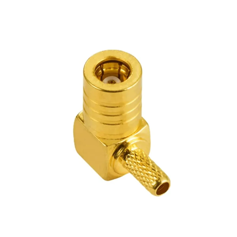
“Right angle” defines the geometry. It does not fully define the direction.
In many assemblies, cable orientation becomes a critical dimension once the connector is terminated. If the buyer expects the cable to exit toward the right side of the PCB and the supplier builds it toward the left, both parts may technically be 90-degree SMB assemblies—and one may still be unusable.
Separate mating rotation from cable-exit orientation
Confirm whether the connector can rotate after mating, whether rotation occurs only during snap-on engagement, and whether the cable exit becomes fixed after termination.
Do not assume the finished cable can simply be twisted into position.
Twisting the coax to correct a wrong elbow direction can transfer torsion into the center conductor, braid, ferrule, strain relief, and PCB connector.
A drawing note could say:
Viewed from the SMB mating face, the cable exits at 3 o’clock.
For tighter assemblies, add:
- viewing direction
- 0° datum
- nominal exit angle
- angular tolerance
- PCB reference edge
- harness direction
- approved installation photo
A golden sample can help production, but the controlled drawing should remain the primary reference.
How does a 90-degree transition affect the RF path?
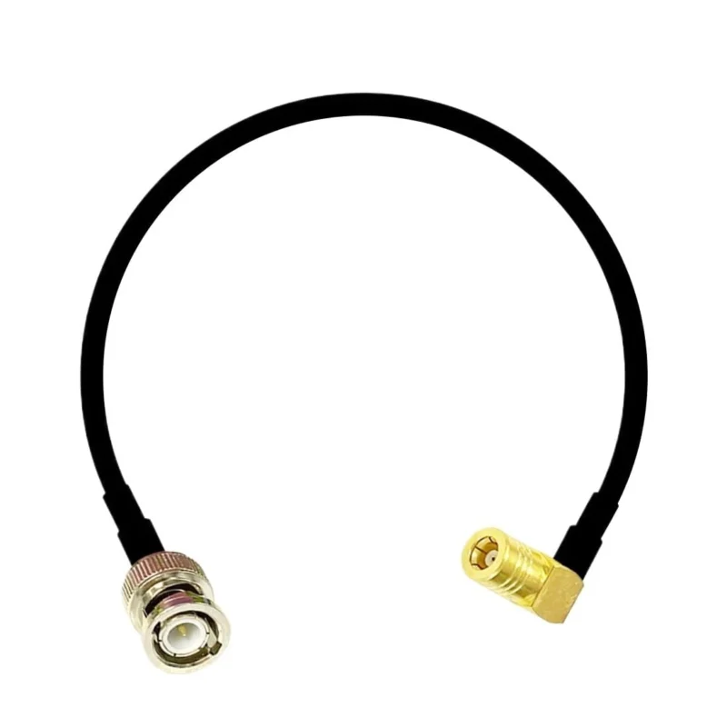
The connector may mate correctly and still need RF verification.
A straight SMB and a right-angle SMB share an interface family, but their internal signal paths are not geometrically identical. The elbow changes the conductor transition, so RF performance should be verified on the actual part rather than inferred from the straight version.
Keep the 50-ohm path continuous through the elbow
For a 50 ohm SMB right angle connector, impedance continuity depends on more than the nominal 50 Ω label.
Center-contact geometry, dielectric support, conductor spacing, termination workmanship, and cable transition all influence the measured result.
IEC 61169-10:2024 covers the standardized 50 Ω SMB snap-on series and gives the family a frequency range up to 4 GHz. For a supplier-specific product claiming operation beyond that standardized range, use the validated data for that exact connector or cable assembly rather than assuming the SMB name itself proves high-frequency performance.
Compare straight and elbow samples on the same fixture
A useful engineering comparison is:
ΔIL(f) = IL₉₀°(f) − ILstraight(f)
Then record the difference across the actual operating band.
Keep the cable, calibration method, fixture, mating connector, and test conditions consistent. Otherwise, the comparison may measure fixture changes rather than elbow geometry.
The test should also use the real cable configuration. RG174 and RG316 versions, different termination workmanship, or a tighter installed bend can produce different results even when the front SMB interface is unchanged.
That distinction becomes important in the next stage: protecting the PCB connector from cable load and validating the finished assembly in the same orientation in which the equipment will actually use it.
Protect the PCB port from side-load and service motion
A 90-degree body redirects the coax. It does not automatically provide strain relief.
If the cable is left unsupported, its weight, vibration, or service movement can still load the SMB interface and PCB-mounted connector. The first cable support should therefore be planned as part of the connector installation, not added after the enclosure layout is finished.
Check the distance from the elbow to the first clamp, harness tie point, or supported service loop. Stiffer coax and connectors with greater overhang deserve more attention.
For early mechanical screening, score cable stiffness, support distance, vibration, service movement, connector overhang, and PCB support from 0 to 2. A higher total does not prove failure, but it is a useful signal to reconsider routing or add mechanical support before release.
If a direct elbow still transfers too much movement to the PCB, compare it with:
PCBSMB → short flexible coax → supported panel connector
A short pigtail can separate the PCB interface from repeated external movement.
When does crimp termination outperform solder?
Do not specify a right angle SMB crimp connector until the actual connector construction is known.
Depending on the design, termination may use:
- crimp center contact + crimp ferrule
- solder center contact + crimp ferrule
- solder termination
The 90-degree geometry adds another constraint: tool access.
A crimp die that works easily on a straight rear body may become awkward around an elbow. Assembly sequence, ferrule position, contact insertion, and cable clocking should therefore be checked using the production tooling.
Detailed strip dimensions and die selection belong in the SMB cable connector termination guide. For this assembly, the critical rule is to establish cable-exit orientation before the final ferrule, boot, or heat shrink locks the geometry.
Validate the finished assembly in its installed orientation
A bench test with the cable lying straight is not the final acceptance condition if production installs it bent, clamped, and enclosed.
IEC 60966-2-1:2024 treats a flexible RF coaxial cable assembly as an integral finished unit and establishes requirements for electrical, mechanical, and climatic testing of the completed assembly rather than its loose parts alone.
That principle is especially useful for a right-angle SMB cable assembly.
Compare at least:
- free cable state
- normal routed state
- cable clamped
- enclosure closed
- after remating
Record S21, S11/S22 where required, continuity, connector retention, and any response to cable movement.
A simple installed-state comparison is:
ΔS21 = S21installed − S21free
The purpose is not to establish one universal acceptable delta. It is to see whether the mechanical installation changes the RF response beyond the project’s own acceptance limit.
Save an installation photo with the first-article RF record. It gives production a reference for cable direction, clamp position, bend geometry, and enclosure condition.
How should first articles and production lots be released?
The first article should prove more than electrical continuity.
Verify:
- correct SMB interface
- correct cable
- right-angle body
- cable-exit direction
- installed height
- ferrule position
- strain relief
- enclosure fit
- required RF response
Visible errors such as wrong gender, wrong cable, damaged interface, or incorrect clocking are suitable candidates for 100% inspection. RF and destructive mechanical tests can follow the sampling level defined by project risk and customer requirements.
A compact release matrix keeps supplier and buyer expectations aligned:
| Characteristic | Method | Typical control | Acceptance basis |
| Interface identity | Visual | 100% | Approved drawing |
| Cable type | Visual/BOM | 100% | BOM |
| Exit orientation | Fixture | Defined plan | Drawing tolerance |
| Continuity | Electrical | 100% where required | Pass |
| Installed height | Dimension | Sample | Drawing |
| Pull retention | Fixture | Risk-based | Project limit |
| S21 / S11 | VNA | Risk-based | RFQ limit |
| Installed fit | Golden fixture | First piece/lot | Pass |
Do not write a generic “RF test passed” requirement if the buyer actually needs a measurable S21, return-loss, or VSWR limit.
Build a drawing that locks orientation and acceptance
“SMB 90° connector” is too short for a production BOM.
A more useful description is closer to:
SMB plug, right-angle cable connector, 50 Ω, for specified coax, defined cable-exit orientation.
The drawing or RFQ should then lock the remaining variables:
- SMB interface and center contact
- coax P/N
- body height and width
- cable-exit datum
- angular tolerance
- finished cable length
- no-bend zone
- frequency range
- insertion-loss limit
- return loss or VSWR
- pull requirement
- sampling plan
This prevents the supplier from having to infer important requirements from a photo or a short part description.
Which failure symptoms point to geometry rather than RF design?
A useful clue is whether the failure appears only after installation.
If an assembly passes on the bench but changes after the lid closes, inspect mechanical conditions before replacing RF components.
Look for:
- lid pressure on the elbow
- cable forced sideways
- incorrect clocking
- clamp-induced bending
- chassis rubbing
- movement at the connector
By contrast, intermittent center-conductor continuity, ferrule movement, or poor braid contact points more directly toward termination workmanship.
A practical sequence is:
Open enclosure → release cable clamps → restore free cable → remeasure → verify clocking → compare with a known-good assembly.
If the elbow repeatedly creates side interference, poor tool access, uncontrolled cable direction, or excessive stress, reconsider the architecture. A bulkhead SMB mounting arrangement or short flexible pigtail may solve the problem more cleanly than adding another adapter.
Which right-angle SMB questions should buyers settle before release?
How should the cable-exit direction be specified?
Define the viewing direction, a 0° reference, nominal exit angle, and angular tolerance. For tightly packaged products, add a PCB reference edge and approved installation image.
How much clearance should remain above a right-angle SMB connector?
There is no single clearance value for every assembly. Calculate it from the mated connector, ferrule, cable OD, manufacturing tolerances, enclosure tolerances, and required service clearance.
Can RG174 and RG316 use the same 90-degree SMB housing?
Do not assume they can. Confirm rear bore, ferrule, contact, cable dimensions, and strip specification for the exact connector P/N.
Why can the assembly pass on the bench but fail after the lid closes?
The installed cable may be compressed, bent differently, pushed sideways, or loaded by a clamp or lid. Compare free-state and installed-state measurements before assuming the connector itself is defective.
Is a right-angle SMB always better in a shallow enclosure?
No. It saves axial space but consumes lateral space and makes cable-exit direction more important. A straight connector may still fit better when side clearance is limited.
When should a short flexible pigtail replace the direct elbow?
Consider a pigtail when the PCB needs mechanical isolation, the cable is relatively stiff, vibration is significant, or the external interface will be moved frequently.
What should incoming inspection record for a clocked elbow?
At minimum, record the SMB interface, cable P/N, exit orientation, dimensional requirement, ferrule condition, continuity, and any project-defined retention or RF sampling results.
A right-angle SMB assembly should be ordered as an installed RF component, not merely as an elbow connector. Before sending the RFQ, provide the mating interface, coax type, cable-exit direction, available enclosure space, operating frequency, cable length, and required inspection limits. Those details make it much easier to determine whether a standard right angle SMB connector is sufficient or whether the assembly needs a controlled custom orientation.
