
Two SMA male cables may thread into the same coupler and still create the wrong RF connection.
The problem is rarely visible during a quick bench check. Continuity passes. Both coupling nuts tighten. The signal reaches the other side. Then the assembled path is swept near its upper operating frequency, and the return loss becomes unstable. In another installation, the RF result is acceptable, but the rigid adapter leaves a long cable hanging directly from an instrument port.
An SMA female to female adapter should therefore be evaluated as both an RF transition and a mechanical component. Interface identity, internal geometry, installation support, mating condition, test method, and lot consistency all affect the final result.
This guide explains how to connect two SMA male cables, isolate the loss added by the adapter, protect equipment ports, select the correct body format, and write an acceptance specification that a supplier can follow.
Verify Both Male Mating Ends Before Choosing a Coupler
Do not identify an SMA interface from the outer thread alone.
For a standard SMA connection, the male side normally has an internal coupling thread and a center pin. The female side has an external thread and a center socket. Reverse-polarity SMA uses the same general coupling arrangement but reverses the center-contact structure.
That difference creates a common sourcing error. A standard SMA male and an RP-SMA male may appear similar in a product photo. Their coupling threads may even begin to engage with the same adapter, but their center contacts are not arranged for the same mating interface.
Check the following fields on both sides before ordering:
- Coupling thread position
- Center pin or center socket
- Standard SMA or reverse-polarity SMA
- Nominal impedance
- Maximum operating frequency
- Port condition
- Cable or device connected to the port
Use the TEJTE RP-SMA Connector Guide as an internal reference when the center-contact arrangement is uncertain.
Complete an SMA Coupler Interface Card
A simple interface record prevents discussions based only on product photos.
| Verification field | Side A | Side B |
| Connected device or cable | ||
| Coupling thread | Internal / External | Internal / External |
| Center contact | Pin / Socket | Pin / Socket |
| Interface family | SMA / RP-SMA / Other | SMA / RP-SMA / Other |
| Impedance | ||
| Maximum operating frequency | ||
| Required adapter side | Female | Female |
When Does a Rigid Coupler Solve the Connection Cleanly?
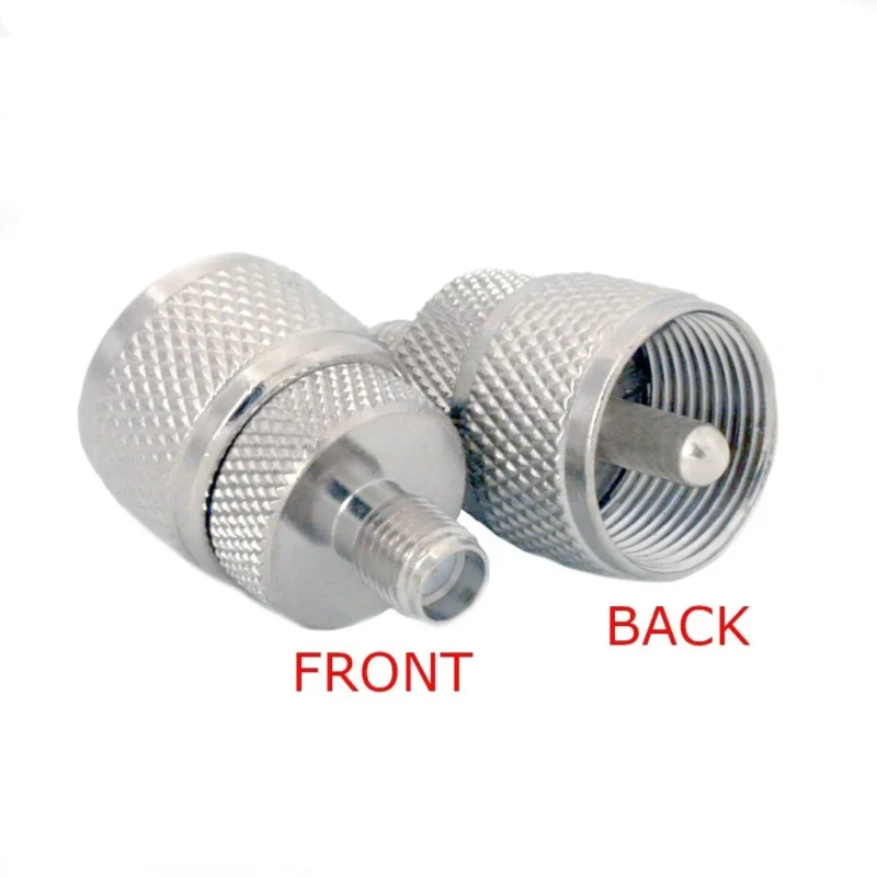
A straight SMA female coupler works best when both male cable assemblies already align without force.
The coupler should not be used as a tool for pulling two misaligned cables together.
Warning signs include:
- Two cables entering the adapter at a visible angle
- A coupling nut being tightened to straighten the cable
- The adapter carrying the weight of a long cable
- One cable pulling sideways against the connection
- The joined point touching a wall or enclosure edge
- No space for a torque wrench or body-holding wrench
A rigid barrel has little tolerance for angular or positional error. Forcing the connection may load the cable termination, deform the mating interface, loosen a panel connector, or transfer bending force into an instrument port.
Use a Coupler-or-Cable Decision Path
Ask these questions in order:
- Are the two SMA male connectors naturally aligned? If not, use a flexible female-to-female cable.
- Will either cable move during operation? If yes, a flexible transition usually handles movement more safely.
- Is the joined point mechanically supported? If not, add a clamp or replace the coupler with a cable assembly.
- Must the signal pass through a panel? Use a bulkhead female-to-female adapter rather than leaving an inline barrel loose.
- Is minimum electrical length the main requirement? A short precision coupler may be useful, but its mechanical loading still needs review.
The lowest component price is not always the lowest installed cost. Port repairs, support hardware, recalibration, labor, and replacement access can outweigh the price difference between a rigid coupler and a purpose-built cable.
How Can You Isolate the Adapter’s Added Loss?
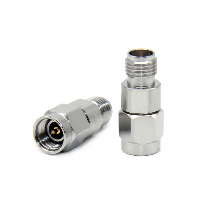
Pair of straight SMA male-to-female RF adapters shown from two angles. The image helps users verify coupling threads and center contacts to prevent adapter gender errors.
A complete cable path contains several loss sources. Measuring only the final path does not show how much came from the coupler.
Start with a defined baseline:
- Calibrate the VNA at the intended reference planes.
- Connect and measure the baseline thru path.
- Save the full S-parameter result.
- Insert the SMA female-to-female adapter.
- Repeat the sweep without changing unrelated cables or routing.
- Compare the two S21 traces across the complete operating band.
The first-order added insertion loss is:
- is the loss added by the adapter at frequency
- is the measured path loss after insertion
- is the original path loss
If a fixture requires two nominally identical adapters, a rough per-adapter estimate may be written as:
Do not divide the total result by two automatically. The estimate becomes weak when the two interfaces, test cables, fixture transitions, or mismatch conditions are not symmetrical.
IEC 61169-1-2:2019 provides insertion-loss test methods applicable to RF cable connectors, microstrip connectors, and RF connector adapters. It is a suitable external reference when a supplier and buyer need to align their measurement procedure.
Save More Than One Frequency Point
A single reading can hide a narrow resonance or upper-band mismatch.
Record at least:
- Start frequency
- Mid-band frequency
- Main application frequency
- Stop frequency
- Maximum added loss
- Average added loss
- Frequency of the worst result
- Calibration date
- Test cable IDs
- Adapter lot number
A change in S21 may include conductor loss, contact resistance, mismatch, contamination, contact-depth variation, and mating repeatability. The calculation isolates the change caused by inserting the adapter into the path; it does not prove which internal mechanism produced that change.
Why Can a Mechanically Compatible Coupler Fail Above 6 GHz?
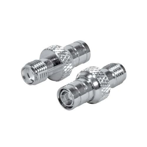
Two compact coaxial adapters illustrating the visible differences between a threaded SMA interface and a snap-on RF connector interface. Confirm interface family, gender, and center-contact structure before use.
Thread engagement confirms only that the coupling structures can mate. It does not confirm controlled impedance through the internal transition.
At higher frequencies, small dimensional changes become more visible in the measurement. Relevant details include:
- Center-contact diameter
- Socket depth and contact engagement
- Dielectric support geometry
- Internal air gaps
- Outer-conductor continuity
- Assembly concentricity
- Surface condition
- Plating consistency
This explains why a coupler may pass continuity and work in a lower-frequency setup but produce poor return loss near the upper end of a wider band.
A catalog statement such as “DC–18 GHz” is useful for initial selection, but it is not a complete acceptance standard. The actual RFQ should state the frequency range, sweep spacing, insertion-loss limit, return-loss or VSWR limit, fixture arrangement, and calibration-plane location.
For a sensitive path, request the full trace rather than a single pass mark. A maximum-frequency label cannot show whether one section of the band contains a sharp mismatch.
The assembled path must also be considered. A compliant adapter connected to worn ports, poorly terminated cables, or an unstable adapter chain may still produce a failed system result.
Protect Instrument Ports from Rigid-Stack Leverage
A small adapter can create a large port load when additional parts extend the distance between the port and the applied force.
Risk increases with:
- Several adapters connected in series
- A heavy attenuator mounted after the coupler
- A right-angle adapter added to the stack
- A long cable hanging from the final interface
- Bench equipment being moved with the cable attached
- Frequent repositioning during testing
A simple bending-moment estimate is:
- is the bending moment at the equipment port
- is the force produced by the cable or attached component
- is the distance from the port to the force location
This formula is for comparing installation risk. It does not replace the mechanical load limit published by the equipment manufacturer.
A light cable located far from the port can create more leverage than a heavier component positioned close to it. Adapter stacks quietly increase both electrical interfaces and mechanical length.
Use cable clamps, fixture brackets, bench supports, panel feedthroughs, short flexible jumpers, or fixed port savers to move the load away from the instrument connector.
Each added adapter should trigger a new review of insertion loss, return loss, mechanical length, loosening risk, and calibration impact.
Which Housing Format Fits Inline, Panel, and Fixture Paths?
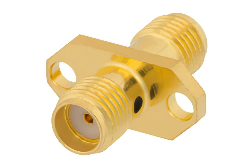
A coaxial adapter with an SMA female interface on one end and a larger UHF male interface on the other. The front and back views support RF connector interface identification.
“Female to female” describes the two interfaces. It does not define how the adapter should be mounted.
Inline Barrel
An inline SMA female coupler is suitable for supported cable-to-cable extensions, temporary bench setups, indoor test paths, and accessible connections.
Its main limitation is low alignment tolerance. The barrel itself does not provide a panel, bracket, or strain-relief point.
Bulkhead Feedthrough
A bulkhead female-to-female adapter is intended to pass the RF connection through a panel.
Confirm:
- Panel thickness
- Mounting-hole size
- Usable bulkhead thread length
- Washer and nut sequence
- Anti-rotation requirement
- Grounding arrangement
- Clearance behind the panel
- Environmental sealing requirement
Using a bulkhead adapter without a panel may work electrically, but the extra thread and hardware do not solve cable-support problems.
Flange-Mount Body
A flange body suits fixed test fixtures, machined enclosures, repeated cable changes, and applications requiring a defined connector position.
The flange controls rotation and position more effectively than a loose barrel. Hole spacing, flange thickness, mounting screws, and keep-out space must match the fixture drawing.
Flexible Adapter Cable
An SMA female to female cable is a different mechanical solution rather than another barrel style. It absorbs offset, permits a service loop, and moves bending stress away from rigid ports.
| Selection factor | Inline barrel | Bulkhead | Flange mount | Flexible adapter cable |
| Main use | Cable extension | Panel transition | Fixed fixture | Offset or moving path |
| Panel mounting | No | Yes | Yes | Optional |
| Alignment tolerance | Low | Medium | Low | High |
| Mechanical support | External support | Panel | Flange screws | Cable clamps |
| Installation movement | Poor fit | Limited | Limited | Better fit |
| Typical concern | Side load | Panel dimensions | Hole pattern | Cable loss and bend radius |
| Panel fit | Installation fixture | When applicable | Approved fit | Rework or reject |
How Should Torque, Cleanliness, and Mating Life Be Controlled?
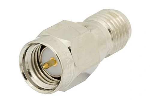
Nickel-plated SMA male-to-female straight adapter with an internal-thread male end, center pin, and external-thread female end. Suitable for illustrating SMA interface and gender identification.
A contaminated or damaged coupler should not be evaluated as though it were a new component.
Inspect both female sockets and outer interfaces for:
- Metal particles
- Dust or oil
- Damaged threads
- Deformed center contacts
- Recessed or loose sockets
- Cracked or displaced dielectric
- Plating wear
- Loose body parts
Clean interfaces using the procedure approved for the connector grade and test environment. Avoid introducing fibers, residue, or excessive mechanical force into the female socket.
Do not assign one permanent torque value to every SMA product. The approved value can depend on connector grade, coupling-nut material, instrument instructions, manufacturer specifications, and the torque-wrench range.
When connecting the second cable, hold the adapter body with the correct tool. Otherwise, tightening one side may twist the first cable, loosen the first interface, rotate a panel connector, or alter the shape of a calibrated test cable.
For repeated test use, assign each coupler an ID and record its approximate mating count, cleaning history, RF verification date, and replacement reason. Mating life should be managed as a maintenance variable rather than treated as an unlimited catalog feature.
Qualify the Coupler Inside the Real Signal Path
A free adapter can pass inspection and still behave differently after installation.
Begin with the loose component:
- Check interface identity
- Inspect threads and center sockets
- Verify DC continuity
- Verify center-to-body isolation
- Check critical dimensions
- Confirm smooth mating with an approved gauge or reference connector
Then repeat the RF test after the adapter is installed with the actual cables, mounting hardware, support arrangement, and normal routing.
Panel compression, body rotation, cable tension, and connector-stack geometry may change the result. The installed-state test is especially useful for fixed fixtures and paths that will be recalibrated as a complete assembly.
For repeated mating evaluation, compare selected cycles:
Useful checkpoints include the first, fifth, and tenth mating, followed by another measurement after cleaning and final fixture installation.
Save the adapter part number, lot number, test cable IDs, calibration date, S2P file location, mating count, measured limits, and approval status. Without traceable records, a later change cannot be separated from cable wear, calibration drift, or adapter degradation.
How Should Incoming Lots Be Sampled and Accepted?
Not every inspection item requires the same sampling plan.
Visual and identity-related risks are inexpensive to check and can often be inspected on every unit. RF sweeps, dimensional reports, retention tests, and environmental checks require a risk-based sample plan.
Suitable 100% checks include:
- Correct interface and polarity
- Thread damage
- Center-contact damage
- Visible contamination
- Correct body and plating appearance
- Included panel hardware
- Label and packaging accuracy
Increase RF and dimensional sampling after a supplier change, plating-process change, machining-tool change, design revision, previous lot failure, customer return, extended production interruption, or higher-frequency requirement.
SMA Female Adapter Incoming Acceptance Matrix
One failed RF sample should not be ignored, but it should also not trigger an unsupported conclusion.
Stop lot release, confirm calibration and fixture status, retest the same adapter, test additional samples, and review machining and plating records. Then determine whether the failure was isolated damage, measurement error, or evidence of lot-level variation.
Build an Unambiguous Supplier Specification
“SMA female to female adapter” is not a complete purchasing description.
Use a fixed sequence:
Interface + body style + impedance + frequency + mounting requirement + test requirement
A stronger description would be:
SMA Female to Female Inline Adapter, 50 Ohm, DC–18 GHz, Full-Band VNA Sample Tested
Add the electrical requirements:
- Nominal impedance
- Minimum and maximum frequency
- Maximum insertion loss
- Minimum return loss or maximum VSWR
- Power requirement, when relevant
- Insulation resistance
- Contact resistance
- Test method
- Calibration-plane definition
Add the mechanical requirements:
- Standard SMA or reverse polarity
- Inline, bulkhead, or flange body
- Overall length
- Wrench-flat size
- Panel thread length
- Panel thickness range
- Mounting-hole or flange pattern
- Body and contact materials
- Plating requirement
- Mating-cycle expectation
Documentation requirements may include a dimensional drawing, certificate of conformity, inspection report, VNA report, lot identification, protective caps, and individual packaging.
The RFQ should also state prototype quantity, production quantity, annual forecast, sampling level, and whether S2P files are required. These details reduce substitutions made solely because two products share the same front-interface description.
Use the TEJTE SMA Adapter Selection and Ordering Guide as the internal link for broader RFQ preparation.
When Should a Flexible Female-to-Female Cable Replace the Coupler?
Replace the rigid coupler when the installation cannot keep both connector centerlines aligned.
A short SMA female jumper cable is usually safer when:
- The ports are offset
- One side moves during service
- The joined point cannot be supported
- A sharp cable bend would start at the coupler
- The equipment port is vulnerable to side load
- The path requires a controlled service loop
An RG316 SMA female to female cable can suit short laboratory transitions, compact fixture routing, elevated-temperature applications, and installations needing moderate flexibility. Cable length, connector construction, bending, and termination quality still affect insertion loss and return loss.
Compare the two complete paths rather than comparing only the adapter and cable prices.
Rigid approach:
Cable A + female coupler + Cable B
Purpose-built flexible approach:
One female-to-female cable assembly
The purpose-built assembly may reduce the number of RF interfaces, but it introduces cable attenuation and requires an exact finished length. The coupler keeps the electrical length short but may increase mechanical risk.
If a permanent system depends on several couplers and short cable sections, redesigning one cable assembly with the correct end interfaces is often cleaner. Specify both genders, polarity, cable type, finished length, routing conditions, test band, and inspection requirements in the BOM.
FAQ
How can adapter loss be separated from the loss of both cables?
Measure and save a baseline path at defined VNA calibration planes. Insert the adapter without changing unrelated cables or routing, then repeat the same sweep. Subtract the baseline insertion loss from the new result at each frequency. More accurate fixture arrangements may require compensation or de-embedding.
Why can an SMA coupler pass continuity but fail at higher frequencies?
Continuity confirms that the conductors are not open. It does not verify controlled impedance. High-frequency performance also depends on contact depth, center-conductor geometry, dielectric support, concentricity, plating, contamination, and interface mismatch. These effects may remain hidden in a DC test.
Should a female coupler remain attached to an instrument port?
It can remain as a port saver when it is included in calibration, inspection, cleaning, and replacement procedures. The coupler adds another RF interface and may increase mechanical leverage. Support attached cables and verify the complete port-plus-adapter path periodically.
When is a short female-to-female cable safer than a rigid adapter?
Use a flexible cable when the two male interfaces are offset, the cable moves, the joined point cannot be supported, or the equipment port may experience side loading. The flexible section absorbs movement that would otherwise be transferred through a rigid barrel.
Can a bulkhead SMA female adapter be used without a panel?
It may pass the RF signal, but the bulkhead structure is intended for panel retention. Without a panel, its longer body, nut, and washer may add weight without providing support. An inline coupler or short flexible adapter cable is usually cleaner for an unsupported cable-to-cable connection.
What wear signs mean an SMA female coupler should be replaced?
Replace the coupler when threads are damaged, the center socket is loose or deformed, the dielectric is cracked, plating wear is severe, or results remain unstable after cleaning. A measurable change in insertion loss or return loss after repeated mating is also a practical replacement trigger.
Final Procurement Note
A female coupler is easy to describe badly because the interface name looks complete. It is not.
Before requesting a quotation, provide the interface family, body format, impedance, operating band, insertion-loss limit, return-loss or VSWR limit, mounting conditions, expected mating cycles, sample quantity, production quantity, and required test records.
For a TEJTE quotation or custom evaluation, include photos of both male interfaces and describe how the completed connection will be supported. That information helps determine whether a rigid coupler, bulkhead adapter, flange body, or flexible female-to-female cable is the lower-risk solution.
