
A cable can pass continuity, mate correctly, and still be wrong for the enclosure.
The problem often appears after installation. The cable is bent more tightly than it was on the bench. The bulkhead body rotates while the nut is tightened. A service loop touches a fan. The panel seal compresses unevenly. At the upper operating band, return loss is worse than expected.
An SMA bulkhead cable is not just an SMA connector attached to coax. It is the complete path between an internal RF module and an external panel interface. Connector polarity, panel thickness, cable family, bend radius, length reference, exit direction, sealing method, and installed RF performance all affect whether that path works in production.
This guide focuses on specifying the finished assembly rather than selecting a bulkhead connector in isolation.
Where should an SMA bulkhead cable sit in the enclosure RF path?
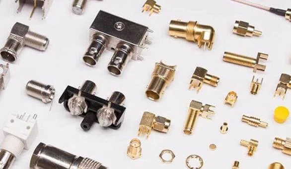
An assortment of RF coaxial connectors and mounting components illustrating straight, right-angle, PCB-mount, and bulkhead interface options.
Start by mapping the entire signal path:
RF module → internal connector → coax cable → SMA bulkhead → external antenna or test cable
This prevents a common sourcing error: treating the bulkhead cable as an independent part without checking what mates to either end.
A cable-backed bulkhead is different from a feedthrough adapter. A feedthrough normally presents an RF interface on both sides of the panel. A bulkhead pigtail has a panel-mounted connector on one end and coax leading to another connector or directly to a device.
Common enclosure layouts include:
- A radio PCB connected to an external antenna port
- A GNSS receiver connected to a rooftop antenna feed
- A test enclosure with front-panel SMA ports
- A sealed gateway with a replaceable external feeder
- An internal miniature connector connected to an SMA panel interface
Write down every interface before requesting a quotation. Adapters added later may solve a mating problem, but they also add another discontinuity, another threaded joint, and another item that can loosen or be installed incorrectly.
Confirm the exact bulkhead interface before ordering
“SMA female” is not a complete specification.
The coupling thread and center contact must be identified separately. Standard SMA and reverse-polarity SMA can use familiar-looking threaded bodies while reversing the center contact arrangement. A product photo taken from the side may not show the difference.
For both ends, record:
- External or internal coupling threads
- Center pin or center socket
- Standard or reverse polarity
- Straight or right-angle body
- Bulkhead, cable-mount, PCB-mount, or miniature internal interface
Name the connector from the mating interface, not from the direction in which the cable runs. For example, an assembly may be described as:
SMA female bulkhead to SMA male straight, RG316, 250 mm
A useful two-end identity record should contain the interface family, thread arrangement, center contact, polarity, mounting style, body direction, mating equipment, and drawing or photograph reference for each end.
Photos help, but they should not replace a drawing. Ask for front and rear connector views, the equipment model, an existing cable label, and the panel installation drawing whenever available.
How do you size the panel-to-board routing envelope?
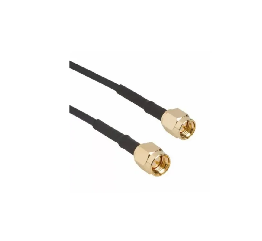
Do not measure only the shortest straight-line distance between the panel and PCB connector.
Measure along the expected cable centerline. Include the bulkhead reference plane, board connector position, horizontal and vertical offsets, required turns, cable exit direction, clamps, heat sinks, shielding walls, fans, batteries, and lid clearance.
A practical preliminary route calculation is:
Lroute = ΣSi + Σ(Ri × θi) + Lservice
Where:
- Si is each straight cable segment
- Ri is the centerline radius of a bend
- θi is the bend angle in radians
- Lservice is the allowance required for assembly and maintenance
This formula is useful in CAD and early prototypes. It does not replace a controlled finished-length definition on the drawing.
Create keep-out zones behind both connectors. The bulkhead needs room for its nut, washer, seal, tightening tool, cable transition, and strain relief. The board end needs insertion space and protection from side loading.
The route must also be checked with the enclosure closed. A cable that looks comfortable with the cover removed may be compressed by a lid, door, battery pack, or internal shield after final assembly.
Which coax family fits the internal bend and loss budget?
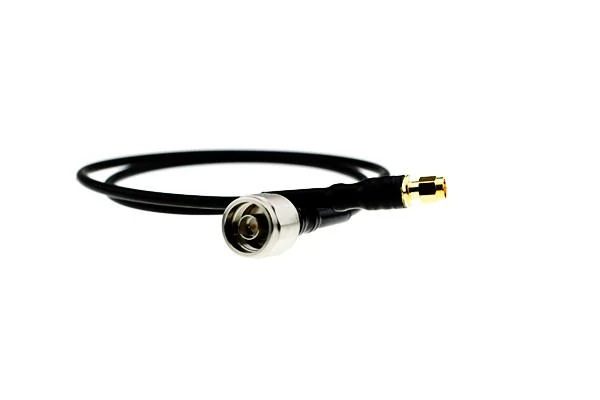
Flexible RF coaxial pigtail used to connect a larger equipment interface to a miniature internal RF connector in space-limited assemblies.
Cable selection is usually a trade-off between routing space, attenuation, temperature, flex behavior, and termination size.
RG174 is often selected for short internal pigtails where flexibility and compact routing matter more than minimum attenuation. RG316 occupies a similar size class but commonly uses PTFE insulation and an FEP jacket, making it useful where higher temperature capability or a different material construction is required. RG58 is substantially larger and usually easier to justify when there is more enclosure space or when a longer run makes cable loss more important.
Manufacturer constructions vary. Published examples place RG174-type cables around 2.6–2.8 mm in outside diameter, RG316 around 2.5 mm, and common RG58 constructions around 4.9 mm. Those figures are useful for initial packaging work, but the approved cable datasheet must control the drawing.
| Selection field | RG174 | RG316 | RG58 |
| Typical size class | Small | Small | Medium |
| Relative flexibility | High | High to moderate | Moderate |
| Common material direction | PE/PVC constructions | PTFE/FEP constructions | PE/PVC constructions |
| Relative attenuation | Higher | Higher | Lower than thin miniature coax |
| Routing space | Tight enclosures | Tight industrial enclosures | Larger enclosures |
| Termination size | Small | Small | Larger ferrule and rear body |
| Common use | Short wireless pigtails | Heat-resistant or industrial pigtails | Longer internal or external runs |
| Main sourcing risk | Excessive loss or tight bending | Assuming all RG316 constructions are identical | Insufficient rear clearance |
A larger cable does not automatically solve every problem. It may reduce attenuation but require a larger connector rear body, a larger no-bend zone, wider clamps, and more room behind the panel.
Cable attenuation also rises with frequency, and larger cables of comparable construction generally reduce loss. The exact loss budget should therefore use the selected manufacturer’s data at the actual operating frequency and finished length.
For a broader comparison of coax families, see the RG cable guide.
Calculate the finished length without creating slack or strain
“200 mm cable” is not enough information for production.
The supplier needs to know where the measurement starts and ends. Possible references include mating plane to mating plane, bulkhead shoulder to mating plane, panel surface to connector tip, connector centerline to mating plane, overall physical length, or jacket length only.
Two assemblies can both be described as 200 mm and still differ enough to create installation trouble.
Add service allowance only where it serves a defined task. Extra length may be required to remove the PCB, reach the locking nut, replace a module, connect test equipment, or follow the enclosure assembly sequence.
Too much slack has consequences. It can create an uncontrolled fold, violate the bend radius, touch a fan, rub against sheet metal, or push continuously against a miniature board connector.
Length tolerance should reflect the route rather than a universal percentage. A 50 mm internal pigtail may need a tighter absolute tolerance than a 2 m external extension. Matched or phase-sensitive assemblies require a separate electrical-length discussion, not just a mechanical tolerance.
Validate the first article in a real enclosure or a representative fixture. A 3D-printed route fixture, golden cable, or centerline template is often more useful than checking a loose cable with a ruler.
Detailed cable attenuation and length budgeting can be handled separately using the SMA RF cable length and loss planning guide.
How should thread length and the panel stack affect the cable build?
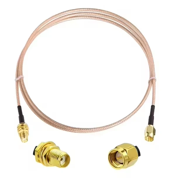
RG316 SMA bulkhead cable assembly designed to route RF signals between an internal module and an external antenna or test interface.
Panel thickness is only one element of the mounting stack.
The complete stack may include powder coating, plating, an EMI gasket, an O-ring, a flat washer, a grounding washer, a lock washer, and the nut. All of these consume thread length or change how the connector seats.
Use the approved connector drawing to verify:
- Thread major diameter
- Threaded barrel length
- Shoulder diameter
- Anti-rotation flat
- D-shaped or round cutout
- Washer outside diameter
- Recommended panel range
Do not publish or purchase against one supposed universal SMA bulkhead hole size. Bulkhead products differ in their anti-rotation features, shoulders, sealing arrangements, and thread lengths.
A simple stack calculation is:
Lremaining = Lthread − Tpanel − Tfinish − Tseal − Twashers
The remaining threaded length must provide adequate nut engagement and support the required locking method. It also needs to leave enough internal clearance for the cable transition and boot.
A thicker panel does not necessarily require a different coax. It usually changes the bulkhead barrel or thread requirement. The cable family should still be selected according to the RF, routing, temperature, and mechanical constraints.
Use the SMA connector dimensions guide to review connector-specific threads, cutouts, and mounting details.
Build a sealing plan for an IP67-targeted assembly
A visible O-ring does not prove that the complete assembly is IP67.
There are at least three possible moisture-entry paths:
- Between the bulkhead body and panel
- Through the external SMA mating interface
- Between the coax cable and connector termination
Each path needs its own control.
The primary panel seal is normally placed on the exposed side, but its actual position must follow the connector design. The drawing should identify the seal location, washer sequence, panel finish, groove geometry where applicable, and installed compression condition.
Also state whether the environmental requirement applies while the connector is mated, protected by a sealing cap, or left unmated. These conditions are not equivalent.
At the cable exit, options may include adhesive-lined heat shrink, a molded boot, potting, a sealing sleeve, or a jacket-compatible sealant. The selected method must not force the cable into an excessive bend immediately behind the termination.
IEC 60529 classifies the protection provided by electrical equipment enclosures against solid objects and water. That enclosure-level context matters: a sealed connector component does not automatically establish the rating of the completed equipment installation.
The final enclosure should be tested in the condition in which the IP claim will be made.
When should the cable exit straight, right-angle, or clocked?
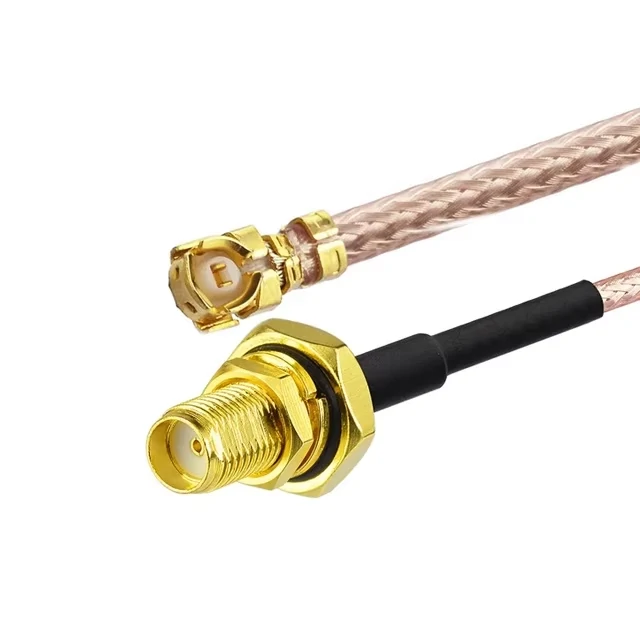
Miniature snap-on connector to SMA female bulkhead coaxial cable for wireless modules, GNSS receivers, gateways, and compact RF enclosures.
Use a straight exit when sufficient axial space exists behind the panel and the cable can enter its bend gradually. Straight constructions are usually easier to clamp, inspect, and re-route.
A right-angle exit is useful in shallow enclosures, front-panel instruments, wall-mounted gateways, or layouts where the PCB connector sits parallel to the panel. It reduces rear depth but makes orientation more important.
Use this decision sequence:
- Is axial clearance greater than the connector transition and required bend zone? Yes: Consider a straight exit.
- Can the cable reach the board without violating the bend radius? No: Consider a right-angle exit or move the bulkhead.
- Must the route avoid a door, fan, shield, or battery? Yes: Define cable clocking.
- Can the connector rotate while the nut is tightened? Yes: Add an anti-rotation feature or installation fixture.
Clocking must include an observation direction, a zero-degree reference, the required exit quadrant, and an angular tolerance. “Cable points left” is not sufficient on a drawing unless the viewing side is also defined.
How do you turn the design into a supplier-ready RFQ?
A supplier should not have to infer polarity, length reference, panel stack, or test conditions from a short product name.
Use a fixed description sequence:
End A + End B + cable family + finished length + frequency + environmental requirement
Example:
SMA female bulkhead to SMA male straight, RG316, 250 mm mating-plane length, DC–6 GHz, panel O-ring included
Then complete a controlled procurement record.
The BOM should describe the usable assembly, not merely “SMA cable.” A procurement line should make substitutions visible before production begins.
For broader end-to-end assembly specification, refer to the SMA cable selection guide.
How should production lots be verified after panel installation?
Start with identity. Confirm connector gender, center contact, polarity, cable type, finished length, mounting hardware, O-ring, and exit orientation.
Then perform DC checks:
- Center-conductor continuity
- Shield continuity
- Center-to-shield isolation
- Intermittent continuity during controlled flexing
- Chassis bonding where specified
Continuity does not prove RF performance. The installed assembly should be swept across the specified band, especially when the cable operates near its practical upper limit or follows a tight enclosure route.
Measure insertion loss and return loss with the cable in its final bent and clamped condition. Tighten the bulkhead using the approved mounting arrangement. Use the defined test adapters and reference planes so that production results can be compared.
IPC/WHMA-A-620F describes materials, methods, tests, and acceptance criteria for crimped, mechanically secured, and soldered cable or wire-harness interconnections. It can support workmanship requirements, but it does not replace application-specific insertion-loss, return-loss, phase, or enclosure sealing limits.
Reference the revision required by the customer rather than copying an older revision from a legacy drawing.
Decide whether to use a stock pigtail or custom assembly
A stock pigtail is reasonable when the interfaces are common, the length tolerance is not critical, the enclosure is dry, and no controlled clocking or special thread length is required.
Typical examples include a standard SMA female bulkhead to SMA male cable using RG174 or RG316 for prototypes, service parts, and low-volume indoor equipment.
Move to a custom build when the enclosure controls the design. Common triggers include:
- A thick or layered panel stack
- Special bulkhead thread length
- A D-shaped anti-rotation cutout
- Fixed right-angle clocking
- Defined service-loop geometry
- Molded strain relief
- Individual labeling
- Waterproofing requirements
- Lot-level or serialized RF test records
Compare integration cost rather than cable price alone. A cheaper stock cable may require an adapter, enclosure rework, more assembly labor, longer test time, or additional inventory. Those costs usually remain hidden until the pilot build.
Which installation mistakes cause field failures?
The first mistake is allowing the cable to twist while the bulkhead nut is tightened. The torque may be transferred into the cable termination or the miniature board connector.
The second is bending immediately behind the crimp, solder joint, or molded transition. Maintain a no-bend zone so that repeated movement is not concentrated at the termination.
Incorrect seal order is another frequent issue. An O-ring may be installed on the dry side, a lock washer may cut into a soft gasket, or the nut may bottom out before the seal is compressed.
Cable clamps can also create problems. A clamp that crushes the jacket or fixes the cable too close to the connector may disturb the route and load the board interface during temperature cycling.
Finally, do not approve a cable only in its loose state. At least one first article should be checked after final routing, clamping, bulkhead tightening, and enclosure closure.
The part may look unchanged. Its mechanical stress condition is not.
FAQ
How much service loop should remain behind an SMA bulkhead?
Use enough cable to complete the intended maintenance task without pulling the board connector or exceeding the bend radius. The correct allowance depends on the enclosure sequence, connector access, clamp location, and board-removal path. A large uncontrolled loop is not automatically safer; it may contact a fan, rub against metal, or fold behind the connector.
Can a right-angle SMA bulkhead cable rotate after the nut is tightened?
Some constructions can rotate during installation unless the body has an anti-rotation flat or is held by a fixture. When direction matters, define the viewing side, zero-degree reference, exit angle, and tolerance on the drawing. A D-shaped cutout or keyed feature may be required.
Should SMA bulkhead cable length include the connector bodies?
It depends on the specified reference points. Length may be measured mating plane to mating plane, bulkhead shoulder to mating plane, panel surface to connector tip, or as overall length. The drawing must identify both measurement references; a number without reference points is ambiguous.
Can RG174, RG316, and RG58 use the same SMA bulkhead hardware?
Do not assume so. Although the front SMA interface may be identical, the cable side usually needs a matching center contact, rear-body bore, ferrule, stripping dimensions, and strain relief. Hardware intended for miniature coax should not be substituted for RG58 hardware without approval.
Does an O-ring make the complete bulkhead cable IP67?
No. An O-ring may seal only the path between the connector body and panel. The external mating interface, cable termination, protective cap condition, and completed enclosure must also be considered. The IP target should be verified after installation in the actual claimed condition.
Can a cable pass RF testing before installation but fail in the enclosure?
Yes. Tight bends, connector rotation, cable crushing, poor clamp placement, and loading at the board connector can change installed performance. Nearby conductive structures may also affect the external antenna system. First-article testing should reproduce the final route and mounting condition.
Is a female bulkhead always the best external antenna interface?
No. The correct interface depends on the mating antenna, standard or reverse polarity, contact-protection requirements, industry convention, and misuse-prevention strategy. A common configuration should not be selected automatically if it creates an adapter or polarity problem elsewhere in the RF path.
Final specification note
Before ordering an SMA bulkhead cable assembly, send the supplier both interface definitions, cable family, finished-length reference, frequency range, panel stack, exit orientation, sealing condition, and required test limits.
Those details are more valuable than a long list of generic performance claims. They allow the supplier to confirm the actual connector hardware, cable termination, routing envelope, and inspection method before the first production lot is built.
