
A cable assembly can pass continuity and still be the wrong RF part.
When should a standard build become a custom SMA cable assembly?The mistake is common because the assembly looks simple: two SMA connectors and a length of coax. The first sample may even work on an open bench. Problems appear later, after the cable becomes longer, bends tighter, runs near the upper operating band, or enters production with an unapproved cable substitution.
A useful SMA cable assembly specification must control more than gender and length. It should define the complete RF path, mechanical references, operating environment, test method, and acceptance limits. Engineers need enough detail to protect the link budget. Buyers need enough detail to compare quotations fairly. Suppliers need enough detail to build the same part repeatedly.
This guide turns a request such as “SMA cable, 300 mm” into a quote-ready and inspection-ready specification.
When should you source a finished SMA cable assembly instead of loose parts?
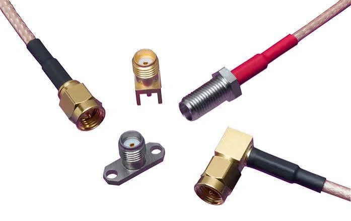
Comparison of several SMA connector body and mounting styles commonly specified for RF cable assemblies. Selecting the correct interface requires checking center contact, coupling thread, mounting method, cable compatibility, and installation orientation.
Buying loose connectors and terminating them in-house can make sense for laboratory work, emergency repair, or a few prototypes. It becomes less attractive when the cable enters an OEM bill of materials.
A finished assembly transfers several process risks to the supplier: cable preparation, center contact attachment, braid contact, ferrule crimping, solder heat control, strain relief, and final inspection. It also reduces the number of tools and operator skills required on the production line.
The real comparison is not connector cost versus assembly cost. It is total process cost. An in-house build may require a controlled stripping process, a calibrated crimp tool, the correct die, soldering instructions, inspection criteria, and RF test capability. A part that looks inexpensive can become costly after rework and inconsistent operator results.
A pre-terminated SMARF cable assembly is usually safer when the cable is part of a released BOM, when right-angle orientation matters, when a bulkhead must fit a panel, when the assembly works near 5.8 or 6 GHz, or when production records are required.
Do not confuse a cable assembly with a rigid adapter. An adapter changes the interface without adding a flexible routing section. An SMA pigtail cable normally has one SMA end and one stripped, soldered, or miniature connector end. A finished SMA connector cable has two controlled terminations and should be treated as a complete component.
How do you identify both cable ends before approving the drawing?
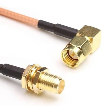
Example of an SMA cable assembly using a right-angle connector and bulkhead interface. Connector gender, polarity, cable type, finished length, mounting dimensions, and operating frequency should all be confirmed before production.
Many wrong orders begin with the words “male” and “female.”
SMA identification uses two separate features: the coupling thread and the center contact. Standard SMA male plugs normally have an internal coupling thread and a center pin. Standard SMA female jacks normally have an external thread and a center socket. RP-SMA reverses the center contact while retaining the corresponding body style.
Product photos cause trouble because the thread is easier to see than the contact. A buyer sees an external thread and assumes “male,” or sees a center socket and assumes “female,” without checking the complete interface.
Create an identity record for End A and End B:
- Coupling thread: internal or external
- Center contact: pin or socket
- Polarity: standard SMA or RP-SMA
- Body style: straight or right-angle
- Mounting style: cable mount, bulkhead, or flange
- Mating equipment port: device model, drawing number, or clear photo
- Reference view: front and side image
This is necessary for an SMA male to SMA male cable, an SMA male to female cable, or an SMA female to female cable. The wording alone is not enough when one side is reverse polarity.
A bulkhead needs extra information: thread length, panel thickness, washer stack, nut, grounding, and sealing hardware. For unfamiliar equipment, confirm the actual port before requesting a quotation. The RP-SMA vs SMA guide provides a more detailed interface check.
Which coax family fits the routing envelope and operating band?
The connector usually gets the attention. The cable often sets the real limit.
Small coax is easy to route but has higher attenuation. Larger low-loss coax preserves more signal but needs more space, a wider bend radius, and larger connector hardware. The practical choice must satisfy both the RF budget and the mechanical envelope.
RF1.13 and RG174 are common in compact products. They suit internal wireless modules, GNSS receivers, short antenna pigtails, and tight enclosures. Their small diameter is useful, but it should not be mistaken for better RF performance. At higher frequencies or longer lengths, loss rises quickly.
RG316 is a balanced option. It is flexible, widely available with PTFE-based construction, and often used in test equipment, short high-frequency jumpers, and assemblies exposed to elevated temperature. An RG316 SMA cable assembly is easier to route than RG58 while offering more mechanical stability than many miniature cables.
RG58 is familiar, durable, and economical. It works well in moderate-frequency equipment and short feeder runs, but its loss at 5.8 or 6 GHz may become the bottleneck before the connector rating does.
LMR195- and LMR240-style cables are better candidates when the run becomes longer or the link budget is tight. They need more space and may be less comfortable in compact moving equipment, but they preserve more RF power over several meters.
Use the actual cable manufacturer’s data. A family name does not guarantee identical conductor size, braid coverage, jacket material, or attenuation.
| Cable family | Routing profile | Relative loss | Typical use | Main caution |
| RF1.13 | Very small, very flexible | High | Internal module pigtails and GNSS | Avoid long runs |
| RG174 | Small and flexible | High | Short antenna leads | Loss rises quickly at high GHz bands |
| RG316 | Flexible and heat-resistant | Medium | RF jumpers and test equipment | Verify real attenuation |
| RG58 | Larger and robust | Medium | General equipment and short external runs | Can be lossy at 5.8–6 GHz |
| LMR195 | Moderate diameter | Low | Longer equipment links | Larger bend radius |
| LMR240 | Larger and lower loss | Lower | Multi-meter feeder runs | Space and stiffness |
The RG cable guide can help compare families, but the drawing should still identify the exact cable or an approved equivalent.
Calculate a quote-ready loss limit before contacting a supplier
“Low loss” is not an acceptance criterion.
The supplier needs a number, a frequency range, and a test reference. Start with cable attenuation, then add both terminations, any adapters, and a practical production margin.
ILtotal(f) = αcable(f) × L + ILA(f) + ILB(f) + ΣILadapter(f) + M
Where:
- ILtotal(f) is finished-assembly insertion loss at frequency f
- αcable(f) is cable attenuation in dB per meter
- L is cable length in meters
- ILA and ILB are connector and transition losses
- ILadapter covers added adapters
- M is design and production margin
Suppose a 1 m cable has 1.2 dB/m attenuation at the target frequency. If both terminations together are estimated at 0.2 dB and a 0.2 dB margin is added, the preliminary limit becomes 1.6 dB.
This is not a substitute for measured supplier data. It is a way to expose unrealistic requirements before quotation.
Insertion loss can also be translated into remaining power:
Remaining power (%) = 100 × 10^(-IL/10)
| Total insertion loss | Approximate remaining power |
| 0.5 dB | 89% |
| 1.0 dB | 79% |
| 2.0 dB | 63% |
| 3.0 dB | 50% |
| 6.0 dB | 25% |
| Finished length | 300 mm |
| Length reference | Mating plane to bulkhead shoulder |
| Tolerance | ±5 mm |
| Frequency range | DC to 6 GHz |
| Insertion loss | Defined maximum across full band |
| VSWR or return loss | Defined limit |
| Power | Average and peak |
| Temperature | Minimum and maximum |
| Jacket | FEP, PVC, PUR, or UV-resistant |
| Environment | Indoor, outdoor, vibration, or sealing |
| Orientation | Straight or defined right-angle clocking |
| Labeling | Part number and lot number |
| Test documents | COC, dimensional report, or VNA plot |
| Quantity | Prototype and annual volume |
| Packaging | Bag, caps, tray, or bundle |
A 3 dB loss means roughly half the input power remains at the far end.
Run the calculation at the frequencies that matter. A short RG316 jumper at 915 MHz may be easy to accept. The same cable family, several meters long at 6 GHz, could consume too much of the link budget.
Write the RFQ in measurable form:
Finished assembly insertion loss shall not exceed 1.5 dB from 2.4 GHz to 2.5 GHz, measured between the connector mating planes.
That can be tested. “Please provide a low-loss SMA cable” cannot. The SMA RF cable length and loss planning guide provides a deeper calculation workflow.
How does 6 GHz operation change the assembly specification?
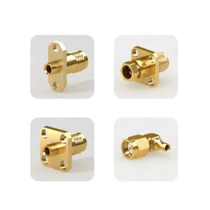
Examples of SMA connector mounting configurations used in RF systems. Flange geometry, panel thickness, connector orientation, usable thread length, and mating interface should be defined clearly on the cable assembly drawing.
At 6 GHz, small assembly details stop staying small.
A cable may pass continuity, use nominally 50-ohm components, and still produce poor return loss because of a distorted dielectric, incorrect ferrule, overlong exposed center conductor, or connector body made for another cable diameter.
Specify the complete operating band rather than one convenient frequency. “Tested at 2.4 GHz” does not prove suitability at 5.8 or 6 GHz. A multiband device may need the assembly checked through the upper band.
A useful test requirement includes:
- Start and stop frequency
- Maximum insertion loss
- Maximum VSWR or minimum return loss
- Calibration plane
- Test adapters
- Cable position during testing
- Report format and sample quantity
The calibration plane matters because launch cables and adapters contribute their own loss and mismatch. Wideband performance must be evaluated as an assembly. Cable geometry, connector transition, crimp quality, solder volume, and bend condition interact.
An 18 GHz connector does not automatically make a long RG174 assembly suitable for 18 GHz service. Buyers also make the opposite mistake: they pay for a higher-rated connector while leaving the lossy cable unchanged. That may improve interface margin but do little for total path loss.
Near the upper band, request a sweep. A single point can miss a narrow mismatch peak caused by assembly geometry.
Which mechanical dimensions must appear on the cable drawing?
“Length: 300 mm” is incomplete.
The drawing must show where measurement begins and ends. Possible references include mating plane to mating plane, connector tip to connector tip, bulkhead shoulder to mating plane, or cable cut length before termination. These values are not interchangeable.
Short assemblies need realistic absolute tolerances. A ±5% tolerance equals ±5 mm on a 100 mm jumper but ±250 mm on a 5 m cable. Long cables may use a combination of absolute and percentage tolerance. Tight internal routing usually needs an absolute limit.
Right-angle connectors require clocking information. Show the viewing direction and cable exit. For right-angle-to-right-angle builds, define whether the ends are parallel, opposed, or rotated 90 degrees.
Bulkhead details should include:
- Panel thickness
- Usable thread length
- Washer arrangement
- Nut
- O-ring or sealing washer
- Grounding requirement
- Maximum protrusion
Add a no-bend zone behind the connector. Repeated stress at the ferrule can break braid strands, pull the center conductor, or disturb the transition geometry.
Minimum bend radius is an installation limit, not a suggestion. When the assembly flexes during service, specify repeated-flex requirements and the bend location.
Build a supplier-ready RFQ with no hidden assumptions
A clean RFQ prevents quotation differences that only appear to be price differences.
Use a consistent part description:
For a sensitive assembly, add a VNA sweep requirement with the required frequency range and limits.
Separate mandatory requirements from preferences. “Must meet” should include drawing, interface, impedance, band, test limits, and environmental constraints. “Preferred” can cover jacket color or label position. “Supplier to propose” can cover a lower-loss cable alternative.
A BOM line such as “SMA cable, 300 mm” invites substitution. A controlled description gives purchasing, engineering, inspection, and the supplier the same reference.
How should incoming SMA RF cable assembly lots be accepted?
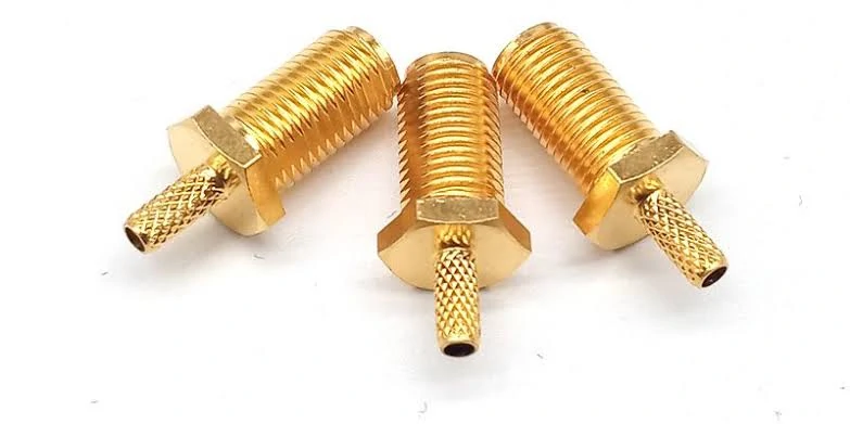
SMA bulkhead crimp connector examples for coaxial cable assemblies. Connector selection should match the coax diameter and construction while controlling panel mounting dimensions, crimp quality, shielding contact, and RF performance.
Start with workmanship, but do not stop there.
Visual inspection can find damaged threads, bent center contacts, loose ferrules, exposed braid, incomplete heat shrink, dirty mating surfaces, missing caps, and incorrect labels. It cannot confirm insertion loss or return loss.
Dimensional inspection should verify finished length, bulkhead thread length, nut stack, cable diameter, connector orientation, and strain-relief position against the approved drawing.
Separate DC and RF checks.
DC checks
- Center conductor continuity
- Shield continuity
- No center-to-shield short
- Insulation resistance when specified
RF checks
- Insertion loss, S21
- Return loss or VSWR, S11 and S22
- Phase or amplitude matching when specified
- Sweep across the operating band
A cable can pass every DC check and still fail at RF. Continuity only proves that the path is electrically connected. It does not prove 50-ohm behavior.
Sampling should follow risk. A standard short assembly used below 1 GHz may need routine visual, dimensional, and continuity checks plus periodic RF verification. A phase-matched group, a 6 GHz production link, or a test-equipment cable may justify wider sampling or 100% VNA testing.
Define the record format. A “test report” could mean a summary sheet, trace plot, Touchstone file, or serialized data. The SMA crimp connector guide explains common strip, crimp, and inspection problems.
Prevent the six order errors that create rework
- Defining gender from the outer thread alone
Check the center contact and confirm standard or reverse polarity.
- Leaving the length reference undefined
Show the exact start and end points on the drawing.
- Treating cable frequency as assembly frequency
Connector transitions and workmanship must support the band too.
- Approving an untested cable substitution
Two 50-ohm cables can differ in attenuation, shielding, diameter, temperature rating, and connector fit.
- Omitting right-angle clocking
A mechanically correct cable can still point in the wrong direction.
- Requesting RF reports without test limits
Define frequency range, acceptance limits, calibration planes, and report format.
These controls do not make the RFQ complicated. They make it usable.
FAQ
How should finished length be measured when one connector is right-angle?
Define a fixed drawing reference. Common choices are mating plane to mating plane, mating plane to connector centerline, or mating plane to bulkhead shoulder. Do not use “overall length” unless the measurement path is shown clearly.
Can an SMA cable assembly pass continuity testing but still fail at RF frequencies?
Yes. Continuity does not detect impedance discontinuity, poor return loss, excessive attenuation, dielectric damage, incorrect ferrule compression, or a connector transition that performs badly near the upper band.
Should insertion loss be specified at one frequency or across the full operating band?
Use a full-band limit for broadband and multiband equipment. A single-point limit is suitable only for a narrow and stable operating frequency. A sweep can reveal mismatch peaks that one test point misses.
When does RG316 become too lossy for a 5.8 or 6 GHz run?
There is no universal maximum length. Use actual attenuation data, multiply it by length, add connector and adapter losses, and compare the result with the link budget. RG316 may suit a short jumper but not a long 6 GHz feeder.
Does every production lot require an individual VNA report?
No. Standard low-risk assemblies may use sample RF testing with 100% visual and continuity checks. Individual reports are more appropriate for high-frequency test cables, phase-matched sets, serialized equipment, or customer specifications requiring full traceability.
How much finished-length tolerance should an OEM assembly allow?
It depends on total length, routing space, connector orientation, and whether electrical phase matters. Short jumpers usually need an absolute tolerance. Long cables may use an absolute value plus a percentage. Phase-sensitive assemblies need a separate phase specification.
When should several SMA cable assemblies be phase matched?
Phase matching is useful in antenna arrays, multi-channel receivers, power-divider networks, synchronized test systems, and calibrated measurement paths. Define the matched group, test band, maximum phase difference, routing state, and test temperature.
Final Practical Note
Before releasing an order, send the supplier both connector identities, cable type, finished-length reference, operating band, insertion-loss limit, VSWR or return-loss limit, environmental conditions, quantity, and inspection requirement.
Those details may add a few minutes to the RFQ, but they remove weeks of confusion from sampling and production. They also make supplier comparisons fair. A cheaper assembly built to a vague description is not necessarily the lower-cost part after rework, testing, and delayed production are counted.
For standard and custom SMA cable assemblies, the most useful starting information remains the same: both interfaces, cable family, length, frequency, environment, and pass/fail criteria.
