
A cable can beep on a continuity tester and still fail when theRF system goes live.
The center conductor is connected. The shield is connected. There is no direct short. Yet the radio still shows reflected power, the CCTV picture remains unstable, or the satellite receiver reports weak signal. The test was not necessarily wrong. The wrong test instrument was used for the decision.
A coax cable tester may be a simple continuity tool, a cable mapper, an active-signal meter, a time-domain reflectometer, or a vector network analyzer. Those instruments do not answer the same question. Before comparing brands, displays, or accessory kits, define the fault and the result you need.
This guide helps engineers, installers, maintenance teams, and buyers select a tester for cable identification, continuity checks, active-signal detection, hidden-fault location, impedance analysis, or RF performance verification.
Start With the Fault You Need to Find
A technician tracing unlabeled F-type cables does not need the same instrument as an engineer qualifying an SMA assembly to 6 GHz. A broadcast team checking a live 75-ohm feed also has a different requirement from a crew locating damage in a long 50-ohm feeder.
Write the task in plain language:
- Find the other end of an installed cable.
- Confirm an open center conductor or broken shield.
- Detect a center-to-shield short.
- Check whether an active signal is present.
- Measure cable length or fault distance.
- Confirm 50-ohm or 75-ohm impedance.
- Measure return loss, VSWR, or insertion loss.
- Save a traceable acceptance report.
A buzzer may suit repair screening, but not a specification requiring S11/S21 traces and a serial-numbered report.
| Project Field | Required Entry |
| Application | RF, CATV, CCTV, satellite, broadcast, lab |
| Impedance | 50 ohms, 75 ohms, unknown |
| Connector | F-type, BNC, SMA, N-type, other |
| Cable access | One end or both ends |
| Suspected problem | Open, short, loss, mismatch, unknown |
| Active signal | Yes, no, unknown |
| Required output | ID, pass/fail, distance, level, S-parameters |
| Report required | Yes or no |
This card prevents buying many features while missing the measurement that decides acceptance.
Which Tester Family Matches the Job?
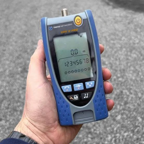
Handheld coax cable tester used for field cable inspection, cable identification, continuity checks, and cable length measurements. Tester capability should be matched to the required fault type, connector, impedance, and measurement output.
A coaxial cable tester should be selected by measurement family, not by the connector shown on the front panel.
Continuity Tester
A coax cable continuity tester checks the DC path. It can identify an open center conductor, open shield, center-to-shield short, or intermittent connection while the cable is moved. Some models include remote IDs.
It cannot prove correct impedance at the operating frequency.
Tone Generator or Cable Mapper
A tone generator is built for identification. It helps locate the remote end of an unlabeled run in racks, walls, conduits, and cable bundles. A mapper may combine identification with open/short detection and numbered remotes.
Check the remote count, connector support, and whether splitters affect tracing. It can save hours during labeling work, but it is not an RF analyzer.
Active-Signal Tester
A coax cable signal tester checks a live service. Depending on the model, it may report signal presence, level, channel, frequency, or service availability. It is useful for CATV, satellite, CCTV, cable internet, and active distribution systems.
“Signal present” does not confirm that cable loss, shielding, or return loss meets specification.
TDR
A TDR sends a fast edge or pulse into the cable and observes reflections. It is used for cable length, fault distance, and impedance discontinuities. It is valuable when the cable is long, hidden, or expensive to replace blindly.
VNA or Cable-and-Antenna Analyzer
A VNA measures S11, S21, return loss, VSWR, insertion loss, and frequency response. Use it when the assembly must be qualified across a band.
| Tester Category | Open/Short | Cable ID | Active Signal | Fault Distance | Impedance | S11/S21 |
| Continuity tester | Yes | Limited | No | Usually no | No | No |
| Tone generator | Limited | Yes | No | No | No | No |
| Cable mapper | Yes | Yes | Sometimes | Model-dependent | Limited | No |
| Signal tester | Limited | No | Yes | No | No | No |
| TDR | Yes | No | No | Yes | Yes | Indirect only |
| VNA | Limited | No | No | With time-domain option | Yes | Yes |
This is not a ranking. A lower-cost tool may be correct for a simple decision.
Does the Tester Match 50-Ohm or 75-Ohm Coax?
For basic open and short checks, reference impedance may not be the main limitation. Once the job includes signal level, return loss, VSWR, characteristic impedance, or fault reflections, impedance matching becomes mandatory.
Wireless, antenna, radio, and RF test systems commonly use 50-ohm coax. CATV, broadcast video, and many CCTV or satellite paths use 75-ohm coax. Confirm the cable and connected equipment.
BNC causes frequent confusion because 50-ohm and 75-ohm versions both exist. They look similar and may physically mate, but their internal geometry differs. A BNC cable tester used for RF work should support 50 ohms. A video or CATV tester should support 75 ohms. TEJTE’s BNC cable selection guide explains why the same connector family appears in two impedance environments.
Do not combine a 50-ohm analyzer, a 75-ohm cable, and an unspecified adapter, then treat the displayed mismatch as a cable defect.
Can the Tester Reach the Real Cable Interface?
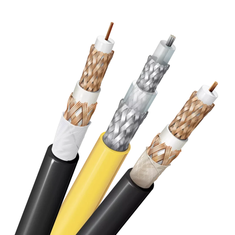
A tester may have the correct function but still fail the job because it cannot connect cleanly to the installed cable.
List every interface before purchasing: F-type, BNC, SMA, TNC, N-type, RCA, miniature snap-on connectors, or bare coax. Then separate native support from adapter-dependent support.
Adapters add interfaces, shift the calibration plane, and may introduce the wrong impedance. At higher frequency, their bandwidth and return loss matter.
Small RF interfaces need extra care. An SMA port should not carry a heavy adapter chain hanging from a stiff field cable. Use a flexible test lead or port saver, confirm gender, inspect the center contact, and apply specified torque where repeatability matters.
For unterminated cable, ask whether the kit includes a stable center-and-shield fixture. Clip leads may be adequate for continuity. They are not a controlled RF transition.
Record the native port, adapter, impedance, qualified frequency, mechanical support, and calibration location. Separate included accessories from optional items.
Is Continuity Testing Enough for This Job?
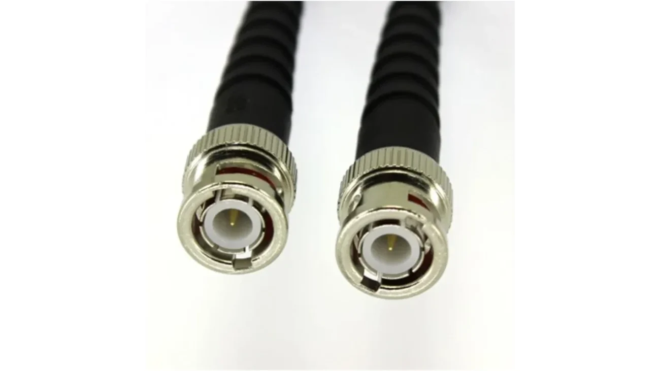
Continuity is enough when the decision is limited to the DC path.
A basic tester can confirm center continuity, shield continuity, and isolation. Moving the connector exit, crimp area, or suspected bend may expose an intermittent break.
The trap is treating a continuity pass as RF acceptance.
A cable may still contain crushed dielectric, partial shield damage, poor braid contact, incorrect connector geometry, water ingress, excessive insertion loss, or high reflections. None of those faults must create a complete DC open or short.
Low-frequency CCTV leads may only need open/short screening and mapping. RF cable assemblies sold against a frequency specification need a qualified RF method. The TEJTE return loss guide explains why reflection behavior cannot be inferred from continuity.
A practical rule: if the acceptance document contains GHz, dB, VSWR, S11, or S21, a buzzer is not the final test instrument.
Do You Need an Active-Signal Tester?
Use a signal tester when the service itself must be checked.
Typical tasks include confirming a CATV feed, satellite signal, CCTV video path, cable-modem connection, broadcast carrier, or another energized coax line. It must support the actual frequency, signal format, level, connector, and impedance.
Input protection deserves attention. Some coax lines carry DC power, bias voltage, remote equipment power, or RF levels beyond a small handheld tester’s rating. Review the instrument limits before connecting it. Do not assume every coax network tester is safe on every live line.
Signal detection is not full cable qualification. A damaged cable may still pass enough energy to show service while producing excessive loss or reflections.
A combined signal meter and mapper may suit installers; engineering teams usually keep service checks and RF qualification separate.
When Does a TDR Earn Its Place in the Kit?
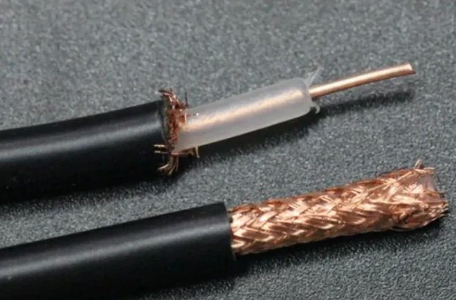
Close-up view of stripped coax cable showing the copper center conductor, dielectric insulation, braided shield, and outer jacket. These conductive paths can be checked for opens and shorts with a basic coax cable continuity tester.
A TDR becomes valuable when the cable disappears into a wall, conduit, tower, vehicle, machine, or long outdoor route.
It can estimate cable length and show reflections from opens, shorts, connectors, crushed sections, splices, or moisture-related changes.
Distance accuracy depends on velocity factor. The TDR measures travel time, then converts time into distance using the cable’s propagation speed. Entering the wrong velocity factor shifts the displayed fault location even when the reflected event is real.
A serious TDR coax cable tester comparison should cover:
- Adjustable velocity factor or cable library
- 50-ohm or 75-ohm reference impedance
- Maximum range and distance resolution
- Dead zone near the test port
- Ability to separate nearby events
- Open/short identification
- Trace storage and export
- Lead or reference-plane compensation
A TDR trace is a location clue. Inspect the corresponding connector, bend, splice, crushed section, or moisture path.
When Must a VNA Replace a Basic Tester?
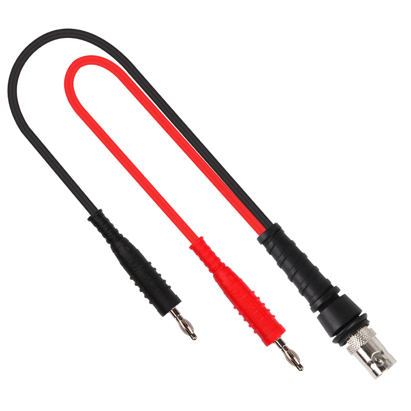
BNC to red and black banana plug test lead designed to access the center conductor and shield separately during basic coax cable continuity, open-circuit, and short-circuit checks.
Use a VNA when frequency-dependent behavior decides whether the cable passes.
A VNA can reveal connector mismatch, poor termination, cable damage, or bend-sensitive behavior that continuity equipment cannot see.
Match the range to the complete application band. Also check the calibration kit, adapters, test leads, and fixtures. A 6 GHz analyzer does not create a valid 6 GHz setup if the adapter chain is only suitable for lower-frequency service.
Two-port capability is required for direct S21 measurement when both cable ends are accessible. A one-port reflection method can help in field work, but its setup and interpretation differ from conventional two-port insertion-loss measurement.
Check SOLT or electronic calibration support, saved states, port extension, de-embedding, and verification standards. Move the calibration plane to the cable interface so adapters and leads do not quietly enter the result.
The RG cable guide helps when the cable family is still uncertain. Cable type, length, shielding, and attenuation may become the bottleneck before the connector or analyzer does.
Which Specifications Actually Change the Result?
Convenience features are easy to compare. Measurement capability is not.
Start with open/short detection, shield testing, cable IDs, reference impedance, frequency range, maximum cable length, fault-distance range, distance resolution, signal-level range, S11/S21 capability, calibration method, and report export.
Read accuracy with its conditions: cable, velocity factor, frequency, adapters, temperature, calibration state, and reference plane.
For traceable work, look for CSV/PDF export, trace files, cable ID, serial number, timestamp, and technician details.
The phrase best coax cable tester only makes sense when the use case is named. The best mapper is not the best fault locator. The best field TDR is not automatically the best instrument for RF assembly qualification.
Use a weighted fit score for internal comparison:
Weighted Fit Score = Σ(weight × score)
Set weights to 100 percent and score each candidate from 1 to 5.
| Criterion | Suggested Weight |
| Required measurement match | 25% |
| 50/75-ohm compatibility | 15% |
| Connector support | 10% |
| Frequency or distance coverage | 15% |
| Reporting and traceability | 10% |
| Field usability | 10% |
| Calibration and support | 10% |
| Included accessories | 5% |
A low-cost tester scoring 5 on the required measurement can be a better purchase than an integrated platform scoring 2 on the same item.
What Belongs in the Complete Test Kit?
The tester body is only one line in the kit.
The package may also need adapters, gender changers, port savers, flexible leads, remote IDs, an unterminated-cable fixture, software, and a calibration certificate.
Keep a verified cable, known open, known short, labeled remotes, and a suitable termination. TDR and VNA setups should also be checked against known references.
Ownership cost includes adapters, replacement leads, software, calibration, repairs, training, and downtime:
TCO = tester + accessories + software + calibration + repair + downtime
Several simple tools may fit better than one integrated platform: continuity plus tone for installation, signal meter plus mapper for CATV, TDR plus basic tester for long runs, or VNA plus controlled adapters for engineering qualification.
Can the Shortlisted Tester Solve a Known Fault?
Do not approve the purchase from a brochure alone.
Ask for a proof test using prepared faults and known references. Demonstrate an open circuit, center-to-shield short, cable identification in a bundle, known cable length, and a known fault position. When active-signal capability is claimed, use an approved source within the tester rating. When VNA capability is claimed, require calibration, S11, S21, a frequency sweep, and result export.
Repeat the test after remating and, where relevant, after moving the cable.
| Demo | Known Reference | Required Output |
| Open/short | Prepared cable | Correct fault indication |
| Cable identification | Labeled bundle | Correct endpoint |
| Active signal | Approved source | Correct presence or level |
| Cable length | Known length | Within stated tolerance |
| Fault distance | Known event | Within stated tolerance |
| S11/S21 | Verified cable | Repeatable trace and export |
This proof test turns product claims into measurable acceptance criteria.
Lock the Requirements Into the RFQ
A useful RFQ does not ask for a “professional coax cable tester.” It describes the work.
Include the application, impedance, connectors, maximum length, active-line condition, required faults, distance resolution, frequency range, signal-level requirement, S11/S21 requirement, calibration method, report format, operating environment, accessories, warranty, and calibration support.
This makes quotations easier to compare and prevents different instrument classes from being offered under one product name.
FAQ
Why Can a Coax Cable Pass a Basic Tester but Fail on a Radio?
A basic tester may verify only continuity and shorts. A damaged dielectric or connector transition can maintain DC continuity while producing RF loss or reflections.
Will a Tone Generator Trace Coax Through a Splitter?
Sometimes. The splitter, connected equipment, and tracing method can divide, attenuate, or block the tone. Verify the mapper on the actual installed path before relying on it for a large labeling project.
Why Does Velocity Factor Change TDR Distance?
A TDR converts signal travel time into distance. Velocity factor tells it how fast the signal moves through that cable. An incorrect value shifts the displayed length and fault location.
Can a Signal Tester Connect to Any Live Coax Line?
No. Check frequency, RF input level, impedance, DC or bias voltage limit, and input protection. Some lines power remote equipment or carry levels that can damage a small tester.
Do Adapters Need to Be Evaluated?
Yes. Adapters may change impedance match, calibration plane, uncertainty, and repeatability. At RF, an unspecified adapter should not be treated as electrically invisible.
When Is a VNA Unnecessary?
A VNA may be unnecessary for endpoint identification, open/short detection, or basic continuity. It becomes appropriate when the cable must be verified for return loss, VSWR, insertion loss, impedance, or other frequency-dependent behavior.
Final Buying Guidance
Select the tester from the fault backward.
Use a continuity tester for open and short checks. Add a tone generator or mapper when the remote end must be identified. Use a signal tester when an active service must be confirmed. Move to a TDR when the cable is hidden and fault distance matters. Use a VNA or cable-and-antenna analyzer when the acceptance criteria include impedance, return loss, VSWR, insertion loss, or frequency response.
Then verify impedance, connector support, range, calibration, reporting, accessories, and ownership cost. The front-panel connector is not the decision. The measurement result is.
For an RFQ, provide cable type, 50-ohm or 75-ohm requirement, connector interfaces, maximum length, operating frequency, suspected fault, required output, and report format. That information makes it possible to specify the correct tester without paying for features that do not solve the actual problem.
