
A coax assembly can pass continuity, fit the enclosure, and still fail after installation. The cable was not terminated incorrectly. The problem began when a small clip flattened the jacket near the connector, forced the cable into a tighter bend, and transferred vibration into the RF port.
That failure is easy to miss because coax cable clips look mechanically simple. In practice, the clip size, contact width, mounting surface, spacing, liner material, and position all affect how the cable behaves. A fastener that holds ordinary wire safely may be too narrow, too rigid, or too loose for an RF cable assembly.
This guide explains how to select, position, and verify a coax cable clamp without crushing the jacket, reducing the bend radius, or making the connector carry the route load. It covers lightweight indoor jumpers, RG316 and RG58 assemblies, vibration-resistant P-clamps, multi-cable supports, vertical runs, outdoor routes, and procurement requirements.
Which Coax Cable Clips or Clamps Fit the Cable and Surface?
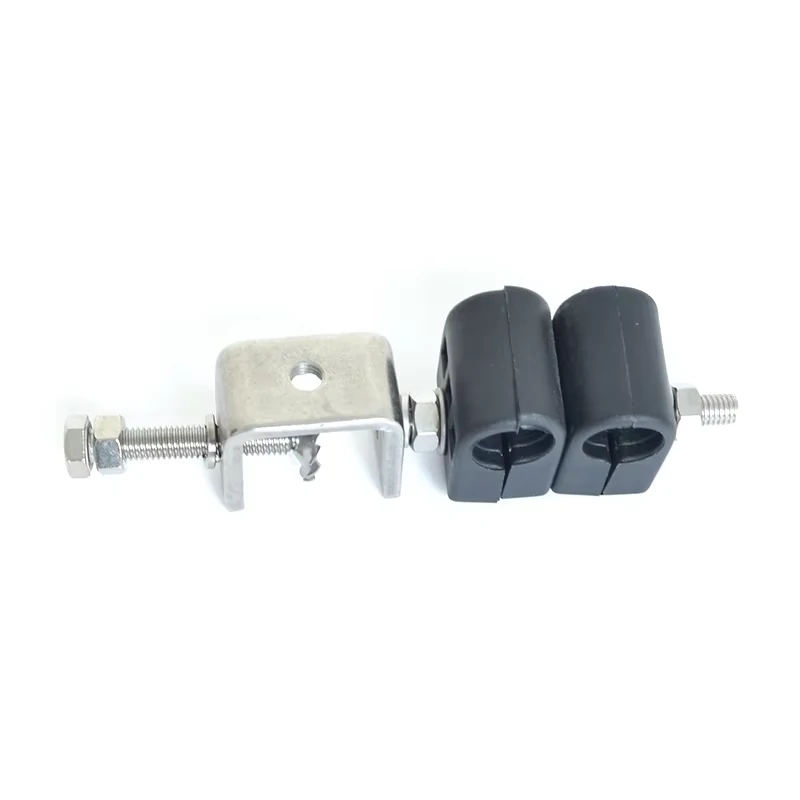
A dual hole coax cable clamp with metal mounting bracket provides reliable mechanical support for RF cable installations. It helps prevent cable movement, vibration damage, and connector strain.
Do not select by appearance alone. Two clips may accept the same nominal diameter but behave differently after closing: one guides the cable, while the other becomes a structural restraint.
Nail-in clips suit lightweight indoor routes on wood. Screw-mounted plastic clips offer better control on panels and frames. Snap-lock or reopenable retainers help inside serviceable enclosures. Adhesive-backed mounts are limited by surface preparation, temperature, aging, and load.
Move to a cushioned P-clamp when vibration, abrasion, or retention becomes significant. Its metal band, liner, and bolted hole spread load more evenly than a narrow plastic finger. Hangers and brackets are reserved for heavy low-loss coax, long vertical routes, mast installations, and feeder runs.
| Cable condition | Preferred hardware | Main selection variable |
| Lightweight indoor coax | Plastic clip | Finished cable OD |
| Small enclosure jumper | Reopenable locking clip | Service access |
| Vehicle or machine | Cushioned P-clamp | Vibration and abrasion |
| Long horizontal route | Support clamp | Sag and cable weight |
| Vertical feeder | Hanger or bracket | Cumulative load |
| Outdoor mast route | UV- and corrosion-resistant clamp | Weather exposure |
| Frequently serviced cable | Releasable clip | Removal cycles |
Use the table only as a starting point. Sleeves, overmolds, and repairs can make the installed diameter larger than the catalog cable value.
How Do You Size a Clip Without Crushing the Coax?
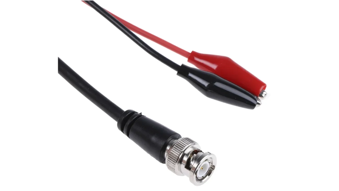
Measure the finished assembly, not only the bare cable. A nominal RG316 diameter does not describe a section covered by heat shrink, a printed identification sleeve, braided protection, an overmold, or a local repair. The largest section that must pass through or sit inside the clip controls the minimum opening.
The fit must prevent opposite failures. Excess pressure can indent the jacket, flatten the shield, compress the dielectric, or disturb impedance. Excess clearance allows sliding, abrasion, connector loading, and position-sensitive results.
A useful dimensional check is:
Nominal Fit Margin = Clip Effective ID − Maximum Finished Cable OD
A negative result indicates compression. Near zero requires a tolerance and closing-force review. A positive result still needs a slip test. No universal margin fits polymer clips, snap-lock retainers, and lined P-clamps.
For lined clamps, nominal diameter may differ from the effective diameter after compression. Contact width matters as well; a wider cushion can hold the cable with less local pressure.
Check fit at the expected temperature and after UV, oil, or cleaning-chemical exposure where relevant. Record cable OD, sleeve OD, clip ID, liner thickness, indentation, movement, and approval status rather than relying on feel.
Where Should Each Clip Be Placed Along the Route?
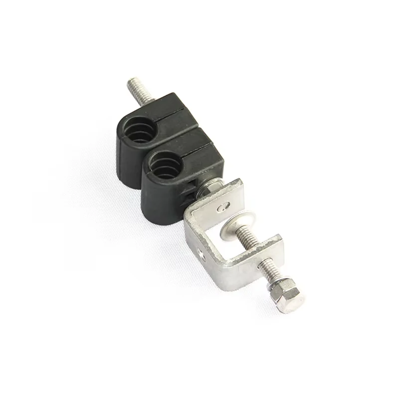
This dual position coax cable clamp is designed for securing multiple RF cables in electronic assemblies. It improves cable routing, reduces vibration stress, and helps protect connectors from mechanical load.
The first support should not be placed simply as close to the connector as possible. It belongs after the connector’s working zone.
An SMA coupling nut needs room to rotate. BNC interfaces need bayonet access. TNC and N-type connectors may require wrench clearance. Snap-on connectors need removal space. The technician also needs to inspect, clean, remate, and replace the assembly without removing unrelated hardware.
Mark the connector reference plane, boot end, straight exit, first allowable bend, and tool-access zone. Place the first clip where it supports the cable without making the boot edge a hard bending point.
Add supports at panel entries, enclosure exits, direction changes, tray entries, and heavy adapter locations. Control service loops so maintenance slack does not swing, rub, or hang from the connector.
Do not copy one fixed spacing value. Cable weight, stiffness, orientation, vibration, wind, mounting surface, connector position, and acceptable sag all matter. For important assemblies, record the trial spacing and measured sag. If a shake or pull check loads the connector, add support or transfer the load to a bulkhead.
What Changes Between Horizontal, Vertical, and Overhead Runs?
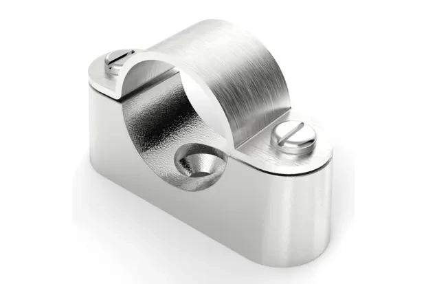
A metal P clamp is used to secure coaxial cables in equipment, vehicles, and industrial systems. Its wide contact surface helps distribute holding force and reduce cable deformation.
Horizontal routing is mainly a sag and abrasion problem. Prevent sharp-edge contact, panel vibration, connector side load, and outdoor low points that trap water.
Vertical routing adds accumulated weight. The upper connector or top clip should not carry the complete drop. Use intermediate load-bearing supports and check for slippage after thermal cycling.
Overhead and mobile routes need closed retention. Open guide clips can release during shock or service; use bolted P-clamps, locking clips, secondary retainers, or brackets where a dropped cable creates risk.
The orientation should be written into the drawing and RFQ. A clamp approved on a horizontal bench route may not be approved for a vertical drop using the same spacing.
Which Materials Survive the Installation Environment?
Material choice is not a cosmetic detail. A polymer clip that works in an indoor rack may become brittle on an outdoor mast. A rubber cushion that controls vibration in a vehicle may soften or swell after chemical exposure.
Polymer options include nylon, polypropylene, acetal, UV-stabilized plastic, and high-temperature grades. Check temperature, UV, humidity, chemicals, fuel or oil, and flammability. Black color alone does not prove UV resistance.
Cushioned clamps may use stainless steel, plated steel, or aluminum with EPDM, silicone, or another liner. Both band and liner must suit the environment and the FEP, PTFE, PVC, PE, or PUR jacket.
Inspect the closed edge. A shifted liner, plastic mold seam, exposed metal, or trapped contamination can become an abrasion point under vibration.
How Do RG316 and RG58 Change the Hardware Choice?
RG316 is usually a compact jumper used in module-to-panel links, SMA assemblies, GNSS pigtails, and test setups. Its small diameter makes it vulnerable to point compression even at modest closing force.
An RG316 cable clamp should provide controlled contact area, avoid forcing a sharp exit bend, and preserve access to the connector. The clip does not need to be heavy, but it must be dimensionally suitable. For broader cable-family context, see the RG316 coaxial cable selection guide.
RG58 is larger and heavier, creating more lever load at SMA, BNC, TNC, or panel interfaces. It usually needs wider support, a stronger fastener, and more clearance. The RG58 cable guide covers loss and routing; clamp selection still follows finished OD and installed load.
LMR-240, LMR-400, corrugated feeder, and other heavy runs may need dedicated hangers, trays, or brackets rather than larger general-purpose clips.
Cable crossing inside a shared clamp changes pressure and bend geometry.
Do not let a larger cable carry a smaller one or force future cables under an existing fastener. Reserve designed positions instead.
How Should Clips Interact With Connectors, Bends, and Service Loops?
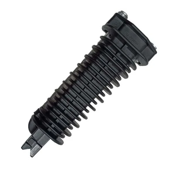
This plastic coax cable clip is designed for cable routing applications where lightweight retention and easy installation are required. It helps maintain cable position while protecting the cable jacket.
A good support system creates a smooth load path from connector, through a straight working section and compliant bend, into the structure.
At every clip exit, the cable should leave on a smooth tangent. Avoid hard bends, reverse bends, kinks, and sharp panel edges. The clip must not reduce the permitted bend radius.
Service loops need maintenance slack without becoming tight coils or uncontrolled moving loops. Use light guides or spaced supports to hold shape without flattening the cable.
Grommets and bulkheads should be coordinated with the clamps. A robust layout often follows this sequence:
RF module → supported internal coax → internal clip → panel bulkhead or grommet → supported external coax
Avoid an unsupported internal cable crossing a sharp panel opening and carrying a heavy external route. The RF cable assemblies guide helps coordinate support with connector count, length, and assembly construction.
What Installation Errors Can Disturb the RF Path?
The cable may still pass continuity after being damaged by a clip. That is why visual and RF checks should be connected.
Look for dents, ovalization, visible shield pattern, cracked sleeves, displaced liners, and compressed overmolds. A permanent mark does not prove RF failure, but it shows local geometry changed.
Forced twist occurs when a clip sits off the natural route, the fastener pulls sideways, or a crossed bundle changes connector clocking.
Hidden compression may appear only after a cover, PCB, heat sink, neighboring cable, or fastener head closes around the route. Inspect the final assembly, not only the open chassis.
| Installation fault | Mechanical symptom | Possible RF symptom |
| Clip too tight | Jacket indentation | S11 or VSWR change |
| Clip too loose | Sliding and abrasion | Intermittent variation |
| Clip misaligned | Cable twist | Phase or loss change |
| Spacing too wide | Sag and vibration | Connector instability |
| Clip at bend tangent | Local kink | Return-loss degradation |
| Exposed metal edge | Jacket wear | Shield damage |
| Hidden cover pressure | Flattening | Position-sensitive result |
| Unsupported vertical run | Connector tension | Intermittent contact |
The RF column is a troubleshooting direction, not a diagnosis; termination, adapters, other cable damage, and test repeatability can cause similar symptoms.
How Can You Verify Retention Without Damaging the Cable?
Start with a baseline: cable identity, OD, clip model and location, route, jacket condition, and electrical results. For critical assemblies, record S11 and S21 over the operating band rather than continuity alone.
Vibration and thermal cycling are application-dependent. They are more relevant for vehicles, outdoor equipment, industrial machinery, portable systems, and high-reliability assemblies. NASA-STD-8739.4 treats clamps as part of mechanical support and strain relief, while Spacecraft Electrical Harness Design Practice emphasizes controlling harness movement with clamps or ties. Those references are useful design context, but they do not replace a commercial RF project’s own dimensions, loads, and acceptance limits.
After the mechanical check, inspect again and repeat RF measurements in the same fixture. Compare return loss, insertion loss, position sensitivity, and phase where required. A meaningful change is a reason to resize or relocate the support before blaming the connector.
A practical acceptance record includes:
- measured cable OD and clip effective ID;
- initial and post-installation jacket condition;
- initial and post-test S11 and S21;
- applied force and hold time;
- measured cable movement;
- clamp rotation or fastener movement;
- final disposition: approve, resize, relocate, or retest.
What Must the Drawing, BOM, and RFQ Specify?
“Install clips where convenient” is not a controlled instruction. It leaves the assembler to decide the hardware, position, orientation, and spacing after production starts.
The drawing should name type, nominal size, effective ID, contact width, material, liner, fastener, finish, and equivalent rules. Dimension the clip centerline from a connector plane, panel edge, or bulkhead center—not a flexible cable feature.
The BOM should state cable nominal and maximum OD, sleeve OD, route orientation, first support position, spacing, temperature, environment, retention, and inspection level. State the frequency range when RF verification is required.
A usable RFQ block looks like this:
Control substitutions. Products with the same listed size can differ in actual ID, liner thickness, stiffness, contact width, hole size, and closing force. Verify approved equivalents.
The broader RG cable guide can help confirm cable family and dimensions before the support hardware is frozen. The 50 ohm coaxial cable guide is also relevant when the route includes several cable families with different mechanical behavior.
When Should a Clip Be Replaced by a Clamp, Hanger, or Bracket?
Upgrade to a clamp when the cable slips, vibration is significant, or connector load rises. Use a hanger or bracket when weight accumulates over a long vertical or outdoor route.
Use a bulkhead or load-transfer bracket when the RF port should not carry the external route. Support the short internal jumper and external cable independently.
Use this decision path:
The final choice should be based on the complete installed system, not the cable name alone.
FAQ
Can a clip sized for bare coax still fit after heat shrink is added?
Not necessarily. Heat shrink, labels, braided protection, repairs, and overmolding increase finished diameter. Measure the largest installed section against the clip’s effective ID; a clip that fits bare cable may crush the sleeved section.
Should a cable clip touch the connector boot?
It should not block coupling, wrenching, cleaning, inspection, or remating, or make the boot edge a hard bend. Position depends on boot length, stiffness, bend direction, and support load.
Can plastic nail-in clips be used inside RF equipment?
They can suit lightweight fixed routing when material, fastener, temperature, and mounting surface match. They are weaker choices for vibration, frequent service, strong retention, or precise positioning.
Why can return loss become worse after the cable is clamped?
The clamp may compress, bend, twist, or load the cable. Compare S11 with the clamp loosened, inspect the route, and confirm the fixture is unchanged. Continuity will not reveal this geometry problem.
Can several RG316 cables share one mounting clip?
Yes, when the support is designed for compatible diameters and no line is crossed, crushed, or blocked from service. Individual clips are better when destinations, labels, replacement schedules, or loads differ.
How can you tell whether coax cable clamp spacing is too wide?
Warnings include sag, vibration movement, panel rubbing, connector side load, and excessive motion. Verify spacing in the installed orientation with the enclosure closed; horizontal spacing may fail vertically or overhead.
Is a rubber-lined cable clamp always safer than a plastic clip?
No. The wrong diameter, liner, contact width, or closing force can still damage the jacket. Check compatibility, edge coverage, temperature, chemicals, movement, and post-installation condition.
Final Buying and Installation Note
Specify coax cable clips as part of the RF route, not as generic hardware after assembly. Provide cable type, maximum finished OD, sleeves, orientation, mounting surface, support positions, spacing, environment, retention, and inspection method.
The clip is acceptable only when it holds the route without crushing the cable, reducing the bend radius, blocking connector access, or transferring mechanical load into the RF interface. Measure it, install it in the final geometry, and verify both the mechanical result and the RF baseline when the application justifies the test.
