
A coaxial cable can pass continuity, mate correctly, and still be damaged by the time the equipment cover is closed.
This usually happens after the bench sample has already passed. The cable is nearly straight during testing, but production routing is tighter. A clamp moves closer to the connector, another harness presses against the bend, or an installer forces the cable around a bracket to gain a few millimeters. The unit may still power up, yet return loss changes, insertion loss becomes position-sensitive, or the cable fails after repeated servicing.
The issue is not simply whether the jacket looks smooth. The real question is whether the installed route preserves the internal coaxial geometry of the exact cable construction.
This coax cable bend radius guide explains how to measure a bend, distinguish static and dynamic conditions, reserve enclosure space, compare RG316 and RG58 routing, inspect hidden damage, and verify the completed assembly with RF measurements. It is written for RF engineers, mechanical designers, production teams, quality inspectors, installers, and buyers who need a bend requirement that can be placed on a drawing or RFQ.
The exact cable model, movement profile, connector exit, and support method all matter.
How Do You Measure the Radius of an Installed Coax Bend?
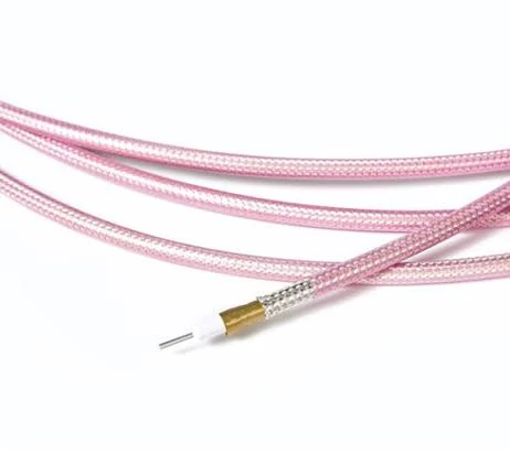
This image illustrates the internal structure of a semi-flexible coaxial cable, including the center conductor, dielectric layer and shielding. Cable construction directly affects bend radius, flexibility and RF performance stability.
The first error is often a measurement error.
A drawing may show centerline radius while an inspector measures the inside jacket surface. A supplier may also state diameter rather than radius. For drawings, centerline radius is normally the clearest reference. If the inside edge is easier to measure, convert it:
Where:
- is the cable centerline radius.
- is the inside jacket radius.
- is the cable outer diameter.
Keep radius and diameter separate:
A 25 mm radius is a 50 mm bend diameter. If a drawing says only “25 mm bend,” production may interpret it either way and create a route twice as tight as intended.
Measure the completed route after connectors, clamps, neighboring harnesses, and the enclosure cover are in place. A loose cable may relax outward but be compressed below its limit after assembly.
Coax Bend Measurement Card
| Field | Required entry |
| Cable manufacturer and model | Exact part number |
| Cable outer diameter | mm |
| Measurement reference | Inside / Centerline / Outside |
| Measured inside radius | mm |
| Calculated centerline radius | mm |
| Manufacturer minimum radius | mm |
| Actual-to-required ratio | Actual ÷ Required |
| Condition | Loose / Installed / Clamped / Closed |
| Inspection method | Gauge / Template / CAD / Photo |
| Result | Pass / Review / Fail |
A route that exactly equals the published minimum has no margin for tolerance, spring-back, or operator variation.
Which Bend Limit Applies to the Actual Motion Profile?
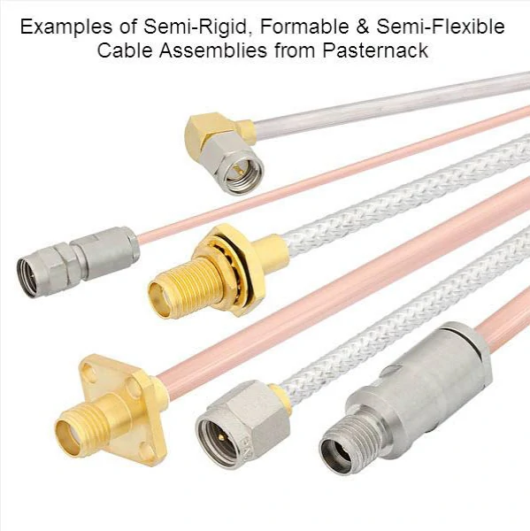
This image shows different types of semi-rigid, formable and semi-flexible coaxial cable assemblies with various RF connectors. These cable constructions are commonly used where controlled bending, compact routing and reliable microwave signal transmission are required.
“Minimum bend radius” is incomplete unless the operating condition is stated.
The same cable may have different limits for installation, fixed routing, repeated flexing, and continuous motion. Using the smallest number without its condition can shorten cable life.
Installation radius
Installation radius applies while the cable is routed, pulled, repositioned, or moved for connector access. It must be considered with pull tension, twist, edge pressure, and temporary kinking. A one-time over-bend can still compress the dielectric or deform the shield.
Static radius
Static radius applies in enclosure harnesses, rack wiring, fixed feeders, and permanently clamped assemblies. ANSI/SCTE 39 establishes or verifies static minimum bending radius for coaxial distribution cable products, tying the limit to a defined product and method rather than a universal multiplier. Thermal cycling, vibration, cable weight, or a tight clamp can still load a fixed route.
Repeated-flex and continuous-flex radius
Use a repeated-flex value for test leads, maintenance loops, hinged covers, and cables moved during calibration. Continuous motion requires a cable designed for the duty, with a suitable conductor, shield, jacket, torsion allowance, dynamic radius, and cycle rating.
| Application state | Radius to control | Additional check |
| Temporary installation | Installation radius | Pull tension and twist |
| Fixed final route | Static radius | Clamp and cover position |
| Occasional maintenance | Repeated-flex radius preferred | Expected service cycles |
| Continuous movement | Dynamic cable rating | Flex-cycle life and torsion |
| Vehicle vibration | Project-qualified value | Vibration test |
| Precision test lead | Repeated-flex radius | Phase and loss stability |
| Unknown movement | Conservative moving condition | Clarify before release |
If the motion profile is unknown, the RFQ is not complete.
How Much Space Must the Enclosure Reserve for the Bend?
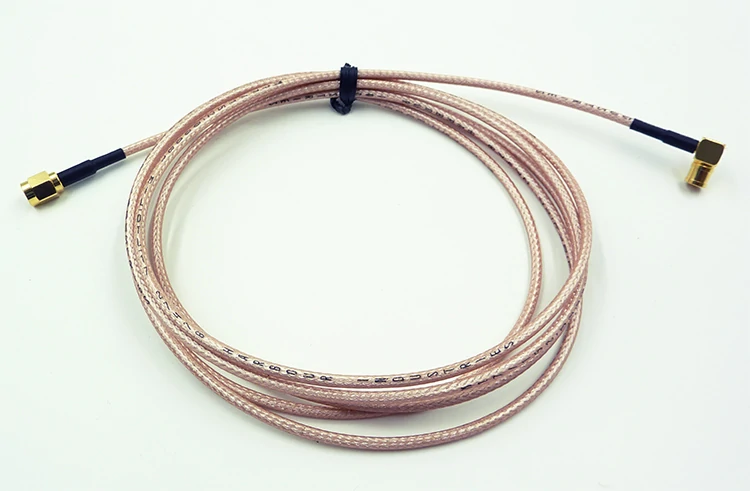
This image shows an RG316 coaxial cable assembly with RF connectors. RG316 cables are frequently used in compact RF systems where small diameter, flexible routing and reliable high-frequency performance are required.
A CAD centerline does not show the full space required by the cable, connector, boot, clamp, and assembly tolerance.
For a 90-degree bend with centerline radius and cable diameter, the outer bend envelope is:
The route also needs room for the connector body, mating access, straight exit, boot, first bend point, clamp, and connector rotation.
Hidden interference often appears only after final assembly, when a cover, heat sink, or adjacent harness reduces the radius. Use a full CAD model or physical mock-up with the real cable and connector, then calculate:
A small positive margin may still be unsafe. Allow for housing tolerance, cable stiffness, connector clocking, and installation variation.
Why Do Two Cables With the Same Diameter Need Different Radii?
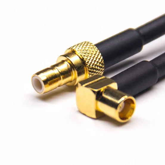
This image shows right angle RF coax connectors used for compact installations. Although right angle connectors change the cable direction, the cable still requires sufficient bend radius, strain relief and proper mechanical support.
Outer diameter is visible, so it is often used as a shortcut for flexibility. That shortcut is unreliable.
Two cables with similar OD may use different conductors, dielectrics, shields, and jackets, changing spring-back, fatigue life, and impedance stability.
A solid center conductor may suit fixed routing but fatigue under repeated movement. A stranded conductor is generally more tolerant of flexing, although “stranded” does not automatically mean continuous-flex rated.
Solid, foamed, and air-spaced dielectrics respond differently to compression. Tight bending may shift the conductor, flatten the cross-section, or change local impedance.
Single braid, double braid, foil-braid, wrapped, and corrugated shields differ in stiffness, crush sensitivity, fatigue, and ferrule load.
PVC, PE, FEP, PTFE, PUR, and low-smoke jackets also behave differently with temperature. A cable routed warm may become much stiffer in cold service.
Cable-Construction Radius Scorecard
| Construction field | Cable A | Cable B |
| Outer diameter | mm | mm |
| Center conductor | Solid / Stranded | Solid / Stranded |
| Dielectric | Solid / Foamed / Air-spaced | Solid / Foamed / Air-spaced |
| Shield layers | — | — |
| Jacket material | — | — |
| Installation radius | mm | mm |
| Static radius | mm | mm |
| Repeated-flex radius | mm | mm |
| Flex-cycle rating | If specified | If specified |
| Application decision | Pass / Fail | Pass / Fail |
Compare exact cable models, not only nominal diameter.
How Should RG316 and RG58 Be Routed Differently?
RG316 and RG58 are often treated as if each name defines one bend-radius value. It does not.
Manufacturers may use different conductor constructions, braid coverage, jacket materials, tolerances, and flex classifications within the same broad RG family. The exact project SKU controls the route.
Use RG316 where compact routing is the main constraint
RG316 is common in compact SMA assemblies, GNSS pigtails, RF modules, fixtures, and short jumpers. Its smaller OD reduces the bend envelope and connector leverage.
For an RG316 bend radius requirement, confirm the manufacturer, exact model, OD, conductor construction, static or moving condition, jacket, connector termination, and first-bend distance. The RG316 coax guide provides additional cable-family context.
RG316 can still fail when movement is concentrated at the ferrule or boot edge.
Reserve more space and support for RG58
RG58 normally needs a larger envelope and applies more leverage to small connectors or PCB interfaces. Check weight, clamps, loop size, ferrule fit, and bulkhead support.
For an RG58 bend radius review, take the number from the selected datasheet and state whether it is an installation, static, or dynamic value. Use the RG58 cable guide to compare routing and application factors.
| Field | RG316 project SKU | RG58 project SKU |
| Cable manufacturer and model | — | — |
| Cable OD | mm | mm |
| Datasheet radius | mm | mm |
| Radius condition | Static / Dynamic | Static / Dynamic |
| Available space | mm | mm |
| Cable weight | g/m | g/m |
| Connector type | — | — |
| First-bend distance | mm | mm |
| Clamp required | Yes / No | Yes / No |
| Installed radius | mm | mm |
| Route decision | Approve / Change | Approve / Change |
Select in this order: available space, motion condition, connector compatibility, bend limit, attenuation, and complete-assembly verification. For broader family selection, refer to the RG cable guide.
Where Should the First Bend Start Behind the Connector?
The termination must not become a hinge.
Do not place a visible bend inside or directly against the crimp ferrule, solder joint, cable-entry shoulder, molded boot attachment, heat-shrink transition, or connector body. These areas already contain abrupt changes in stiffness and internal geometry.
The drawing should identify the connector reference plane, exit length, boot, straight relief, first bend tangent, first clamp, and required centerline radius. “Minimum bend radius 15 mm” does not tell the installer where bending may start.
A boot may soften the transition, but its edge should not become a hinge. Repeated movement can cause braid fatigue, jacket cracking, intermittent contact, or position-sensitive S11.
A right-angle connector changes direction but does not eliminate bending. The exiting cable still needs radius, torsion relief, support, and slack, while clocking and elbow height must fit the enclosure.
For a heavy external cable connected to a small PCB interface, consider a short supported pigtail and panel bulkhead. That prevents the external route from loading the board connector directly. The RF connector installation guide also helps define mating, torque, and routing controls near the interface.
How Can You Spot Hidden Damage From an Over-Tight Bend?
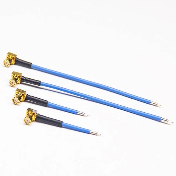
This image shows SMA connector semi-flexible coaxial cable assemblies commonly used in RF test equipment, laboratory measurement systems and microwave applications requiring stable impedance and controlled cable routing.
Visible damage is only the first inspection level.
Warning signs include jacket whitening, flattening, kinks, cracking, shield impression, permanent set, connector misalignment, or hard spring pressure against the housing.
Move the cable gently within its normal service range and watch for:
- signal interruption;
- insertion-loss fluctuation;
- return-loss spikes;
- receiver noise;
- intermittent continuity;
- phase shift;
- failure only near the highest operating frequency.
Continuity cannot prove stable 50-ohm geometry, shield shape, insertion loss, return loss, or electrical length.
Do not approve a kinked cable simply because it was straightened. The jacket may recover visually while the dielectric remains compressed and the center conductor stays displaced.
Over-Bend Inspection Decision Tree
For production inspection, use a radius template, gauge, or fixture rather than “looks smooth.”
Which RF Measurements Prove the Bend Is Acceptable?
Sensitive assemblies need more than mechanical inspection.
Record a relaxed-state baseline: cable ID, connector torque, reference planes, adapters, sweep, temperature, cable position, S11, S21, and phase where relevant.
Place the cable at the required radius using a smooth mandrel, fixture, or representative enclosure. Keep connector mating, clamp position, orientation, test ports, and sweep settings unchanged.
Useful comparisons are:
These calculations show bend-related change but do not define a universal limit. The project must set limits from its band, loss budget, return-loss target, and sensitivity.
Test three states when possible:
- relaxed baseline;
- cable held at the required installed radius;
- cable released after bending.
The third state reveals permanent deformation when the response does not return close to baseline.
Phase testing is relevant to matched assemblies, arrays, radar, beamforming, and precision test cables. IEC 61196-1-111:2024 includes methods for phase behavior with bending and twisting.
Bend Qualification Test Sheet
| Test field | Baseline | Bent state | Post-recovery |
| Bend radius | — | mm | — |
| Bend angle | — | degrees | — |
| Worst-case S11 | dB | dB | dB |
| Worst-case VSWR | ratio | ratio | ratio |
| S21 | dB | dB | dB |
| Electrical phase | degrees | degrees | degrees |
| Continuity | Pass / Fail | Pass / Fail | Pass / Fail |
| Permanent set | — | — | Yes / No |
| Final decision | — | — | Approve / Reject |
Phase may be unnecessary for a general jumper but essential for a phase-sensitive microwave path.
How Should Clamps, Grommets, and Service Loops Shape the Route?
Routing hardware should preserve the required radius, not create a new sharp bend.
A clamp can solve pull load while causing a radius problem. Check its position, entry and exit angles, width, jacket compression, and radius on both sides.
Use a grommet for abrasion and edge protection, not as a substitute for a smooth bend. The opening and approach angle must not force a sharp local radius.
Size service loops from centerline radius. Provide maintenance slack without reverse bends, vibration, heat-sink contact, or cable weight hanging from the port.
Extra cable is not always safer. A large unsupported loop may vibrate and repeatedly load the connector.
| Routing element | Radius risk | Required check |
| Cable clamp | Sharp exit | Clamp angle and spacing |
| Grommet | Small local edge | Opening and liner shape |
| Cable tie | Jacket compression | Tie width and tightness |
| Service loop | Reverse bend or vibration | Loop diameter and support |
| Bulkhead | Bend near termination | Straight exit distance |
| Enclosure cover | Hidden compression | Closed-condition inspection |
| Cable bundle | Route distortion | Final assembled radius |
Strain relief and bend radius are separate checks. Both must pass after final assembly.
What Bend-Radius Data Must the Drawing Control?
A usable drawing identifies the exact cable, the bend condition, and the acceptance method.
Include the manufacturer or approved equivalent, model, RG designation, impedance, OD, conductor, shield, and jacket. “RG58, 50 ohm” does not control flexibility.
Do not write only:
State whether the value is:
- minimum installation bend radius;
- minimum static bend radius;
- minimum repeated-flex bend radius;
- minimum continuous-flex radius;
- minimum radius at the connector exit.
Dimension the bend centerline, tangent points, angle, connector reference plane, straight exit, first clamp centerline, service loop, panel opening, and mechanical tolerance.
Mechanical compliance should connect to RF acceptance:
Coax Bend-Radius RFQ Block
This information prevents the supplier from quoting a cable that mates correctly but cannot survive the real route.
When Should the Cable or Connector Architecture Change?
Reject a route that works only when the cable is forced into position.
A smaller cable may solve space, but recheck attenuation, power, shielding, temperature, connector availability, mechanical life, and length.
Repeated movement may require stranded or ultra-flex construction, a dynamic-rated jacket, documented cycle life, and a motion-capable termination.
For a right-angle connector, verify body height, orientation, clocking, mating access, exit radius, and added RF transition.
For a heavy cable connected to a PCB port, use:
PCB RF Port→ Short Supported Pigtail→ Panel Bulkhead→ External Coax Cable Redesign is required when the cable springs against the enclosure, the cover compresses the bend, the bend starts inside the crimp, a clamp forces a kink, mating requires twist, the installed radius cannot be inspected, or S11 and S21 change with normal cable position.
| Problem | Preferred change |
| Required radius does not fit | Smaller or more flexible cable |
| Downsizing causes excessive loss | Shorter route or lower-loss cable |
| Bend starts at connector | Right-angle connector or rerouting |
| Heavy cable loads PCB port | Bulkhead pigtail |
| Repeated movement damages cable | Flex-rated assembly |
| Service loop does not fit | Reposition ports |
| Clamp creates a kink | Move or redesign support |
| Tight route changes RF results | Increase radius or change assembly |
The correct fix may involve the cable, connector, enclosure, or all three.
FAQ
Is coax cable bend radius measured from the inside edge or the cable centerline?
Centerline radius is usually the clearest drawing reference, but datasheets may use another convention. Confirm the basis before comparing a supplier number with a mechanical drawing. If the inside radius is measured, add half the cable OD to obtain the centerline radius. State the reference on the drawing and inspection report.
Can a coax cable be bent below its specified radius once if it will never move again?
It should not be assumed safe. A single over-tight bend can compress the dielectric, flatten the shield, shift the center conductor, or create a permanent set. The cable may still pass continuity while return loss, insertion loss, or phase has changed. Reroute and test it when the application is sensitive.
Can a kinked coax cable be reused after it is straightened?
Straightening the jacket does not prove that the dielectric, shield, and center conductor returned to their original positions. For low-risk service, inspect and test the cable. For microwave, phase-sensitive, high-power, or reliability-critical use, replacement is usually safer.
Should bend radius be inspected before or after the cable is clamped?
Both checks are useful, but final acceptance must use the completed installed condition. Clamps, ties, covers, panel edges, and neighboring harnesses can reduce the radius after the cable initially passes. The closed enclosure is the condition that matters in service.
When should phase stability be tested in addition to insertion loss?
Phase testing is valuable for phase-matched assemblies, antenna arrays, radar, beamforming, precision test systems, and other paths where electrical length affects accuracy. Define the radius, bend angle, cable position, frequency sweep, and maximum permitted phase change.
Final Practical Guidance
Do not approve a route because the cable looks smooth or because another cable with the same RG name worked before.
Use the exact datasheet. State whether the limit is installation, static, repeated-flex, or continuous-flex. Measure the final centerline radius with the cable mated, clamped, and enclosed. Keep the first bend outside the termination. Reserve space for the connector, straight exit, clamp, and service loop. For tight or sensitive RF paths, compare S11, S21, and phase in relaxed, bent, and recovered states.
For purchasing, send the supplier the cable model, connector interfaces, length, impedance, operating frequency, movement condition, required installed radius, first-bend distance, and inspection level.
A bend-radius requirement is not a minor mechanical note. It is part of the RF specification.
