
The adapter threaded onto both ports, so the installer assumed the connection was correct. The outdoor antenna used an N-Type connector, the wireless bridge used what looked like SMA, and the adapter body sat neatly between them.
The link still failed.
A closer inspection found that the device port was RP-SMA rather than standard SMA. The threads could engage, but the center contacts did not form the intended RF path. This is one of the more expensive mistakes hidden inside a small, inexpensive component.
An N to RP-SMA adapter must match more than two connector names. Buyers need to confirm the N-Type gender, the RP-SMA thread and center-contact arrangement, the operating frequency, mechanical loading, installation environment, and RF acceptance limits.
Can You Identify RP-SMA Without Trusting the Label?
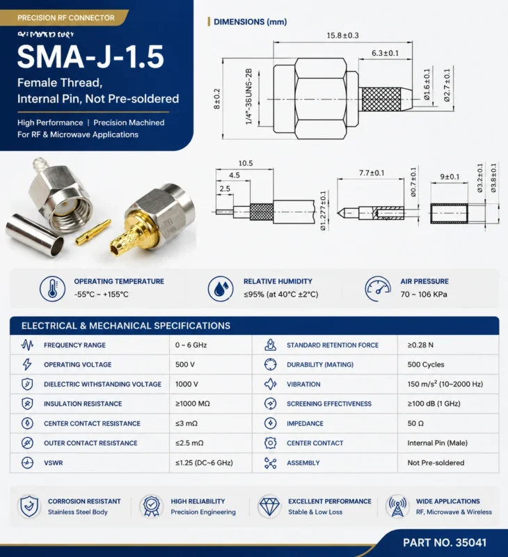
Product titles are not always reliable. Some marketplace listings describe any small threaded RF connector as “SMA,” even when the center-contact polarity has been reversed. Others use male and female terminology based only on the visible thread.
That shortcut causes ordering errors.
For SMA and RP-SMA interfaces, identify two features separately:
- Is the thread external or internal?
- Is the center contact a pin or a socket?
Standard SMA male normally has an external thread and center pin. Standard SMA female normally has an internal thread and center socket.
RP-SMA keeps the general thread arrangement but reverses the center-contact configuration. A common RP-SMA male has an external thread and center socket. RP-SMA female has an internal thread and center pin.
The word “reverse” refers to the center-contact polarity. It does not mean that the male and female thread arrangement is simply swapped.
The practical identification grid below is more useful than a product title.
A buyer reviewing an unknown port should record all four of these fields:
- Thread position
- Center-contact type
- Port location
- Expected mating interface
A clear front-facing photograph helps. A drawing is better. For production orders, the drawing should control the decision.
The RP-SMA polarity guide provides more detail on recognizing reverse-polarity interfaces. It is useful when a router, radio, antenna cable, or wireless module is poorly labeled.
Reject incomplete purchasing descriptions
This description is risky:
N to SMA adapter
It does not identify:
- Standard or reverse polarity
- Gender at either end
- Impedance
- Orientation
- Frequency range
A workable description would be:
N-Type Male to RP-SMA Female Adapter 50 Ohm Straight Operating Frequency: DC to 6 GHz or supplier-confirmed range
The exact frequency rating must come from the selected part, not from the connector-family name.
Which N-to-RP-SMA End Pair Matches the Installed Hardware?
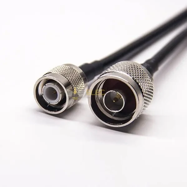
Close-up view of a coaxial cable assembly with an N-Type connector and a smaller threaded RF interface. Cable assemblies can reduce mechanical stress on an RP-SMA equipment port compared with a rigid N to RP-SMA adapter.
Start with the installed ports. Do not start by browsing adapter listings.
For the N-Type side, record:
- N male or N female
- Center pin or center socket
- Equipment port or cable end
- Nominal impedance
- Indoor or outdoor location
N-Type connectors are often used on outdoor antennas, feeders, base-station equipment, wireless bridges, and protected enclosures because their threaded coupling is mechanically stronger than a small SMA-family interface. That does not make every N-Type connector identical. Different impedance and frequency configurations exist.
Next, inspect the RP-SMA side independently:
- External or internal thread
- Center pin or socket
- Device-mounted or cable-mounted
- Straight or recessed location
- Available clearance around the port
The required adapter has the mating interface for each installed port.
| Existing N-Type Port | Existing RP-SMA Port | Required Adapter |
| N Female | RP-SMA Female | N Male to RP-SMA Male |
| N Female | RP-SMA Male | N Male to RP-SMA Female |
| N Male | RP-SMA Female | N Female to RP-SMA Male |
| N Male | RP-SMA Male | N Female to RP-SMA Female |
| Unknown | Unknown | Inspect both ports before ordering |
The keyword order does not determine the physical direction. An “RP-SMA female to N male adapter” and an “N male to RP-SMA female adapter” may describe the same interface pair.
What matters is the geometry at both ends.
For an installed N female antenna port and an RP-SMA male radio port, the adapter must provide:
Connector A: N-Type Male Connector B: RP-SMA Female
The buyer should still verify that the RP-SMA female end has an internal thread and center pin. Naming errors do occur in catalog data.
Why Can the Threads Fit While the Signal Path Still Fails?
Thread engagement is only one part of mating.
A mismatched SMA and RP-SMA pair may appear to tighten normally while the center contacts are wrong. Two center pins can interfere mechanically. Two center sockets can leave the RF path open. Marginal contact can produce intermittent behavior that changes when the cable is moved.
Typical symptoms include:
- No RF output despite a tightened connector
- Unstable received signal strength
- Link failure after vibration
- Continuity that changes when the adapter is touched
- High return loss
- Unexpected insertion loss
- Damaged or recessed center contact
Mechanical inspection and electrical inspection must be separate.
A basic first check should cover:
- Thread engagement
- Center-contact pairing
- Shell continuity
- Center continuity
- Center-to-shell isolation
- RF response across the operating band
A continuity test can identify a completely open path, but it does not prove acceptable RF performance. A poorly aligned contact may still pass a low-frequency resistance test and fail near 5 or 6 GHz.
The SMA versus RP-SMA comparison is useful when the port family remains uncertain after visual inspection.
Avoid repairing the interface with an adapter chain
This arrangement is possible, but usually poor:
It introduces another interface, another body joint, and another opportunity for a polarity or gender mistake.
Will the Adapter Meet the 2.4, 5, or 6 GHz Link Budget?
A connector-family rating is not the same as a finished-adapter rating.
The usable system frequency is limited by the lowest-rated component:
A radio may support a 6 GHz band while the selected adapter, cable, or antenna was validated only to a lower frequency. The component can still mate mechanically. The RF result is the problem.
Use the manufacturer’s data for the exact SKU. For commercial sourcing, request a drawing and measured or specified RF limits. Do not assume that every RP-SMA to N-Type adapter shares the same frequency range.
The Amphenol RF RP-SMA connector information provides useful reference material for common RP-SMA applications and configurations. It should not replace the selected supplier’s part-specific data.
Add every passive loss to the same budget
A passive adapter does not increase antenna gain. It adds a transition and normally introduces some loss.
A simplified estimate is:
At 2.4 GHz, a short cable may be acceptable. At 5 or 6 GHz, the same cable type and length can consume more of the link margin.
The Wi-Fi antenna cable loss guide explains why cable length, cable family, and interface count should be reviewed together.
If the remaining margin is small, do not solve the problem by selecting a part with a more optimistic product title. Shorten the cable, reduce interface count, select a lower-loss feeder, or request measured data.
Convert VSWR into a usable return-loss requirement
Some RFQs state only “low VSWR.” That is not measurable enough.
The limit should apply across the required frequency range, not only at one convenient test point.
Where Should the Indoor-to-Outdoor Boundary Be Placed?
The N-Type side usually belongs near the mechanically demanding part of the installation. The smaller RP-SMA side normally belongs near the radio, access point, router, or compact enclosure.
A common layout is:
Outdoor Antenna→ N-Type Connection→ Outdoor Low-Loss Feeder→ Protected Enclosure Boundary→ Short RP-SMA Transition→ Radio This arrangement keeps the heavy feeder load away from the radio’s small connector.
Do not assume that the complete connection is waterproof because the N-Type end is described as weather resistant.
The entire assembly must be checked:
- N-Type mating seal
- Adapter body joints
- RP-SMA connection
- Panel seal
- Cable entry
- Connector orientation
- Drain path
- Environmental test evidence
An exposed RP-SMA joint may become the weak point. It is smaller, often less protected, and may not include the sealing structure required by the installation.
For permanent outdoor work, a bulkhead or cable assembly may be safer than a rigid inline adapter. It allows the enclosure wall or bracket to carry mechanical load and provides a defined location for sealing.
When Does a Rigid Adapter Overload the RP-SMA Port?
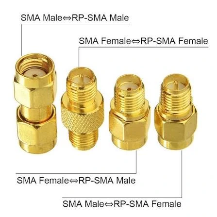
Visual comparison explaining the difference between standard SMA and reverse-polarity SMA connectors. RP-SMA retains the general thread arrangement of SMA while reversing the center pin and socket configuration, so thread appearance alone cannot confirm compatibility.
A rigid N-to-RP-SMA adapter places the larger N-Type body and attached cable directly onto a much smaller connector. The assembly may be electrically correct and mechanically poor.
The approximate bending moment at the equipment port is:
Where:
- (M) is the bending moment at the RP-SMA port
- (F) is the side force or cable load
- (d) is the distance from the panel to the load point
A longer adapter increases (d). A heavier or stiffer feeder increases (F).
High-risk layouts include:
- LMR-400 or similarly stiff cable
- Unsupported horizontal feeder
- Long straight adapter
- PCB-mounted radio port
- Vehicle vibration
- Industrial machinery
- Repeated equipment movement
- Sideways cable routing
- Tight cable bends immediately behind the adapter
A simple screening score can help during design review:
Port Stress Score =Adapter Length+ Feeder Weight+ Cable Stiffness+ Side Pull+ Vibration+ Port Support Weakness Rate each item from 1 to 5.
6–10 points: Rigid adapter may be acceptable. 11–18 points: Add support and repeat the mechanical inspection. 19–30 points: Use a flexible pigtail, supported bulkhead, or bracketed transition.
This is an engineering screening tool, not an industry standard. Its purpose is to force the installation team to discuss mechanical load before field failure.
Which Architecture Fits the Installation Best?
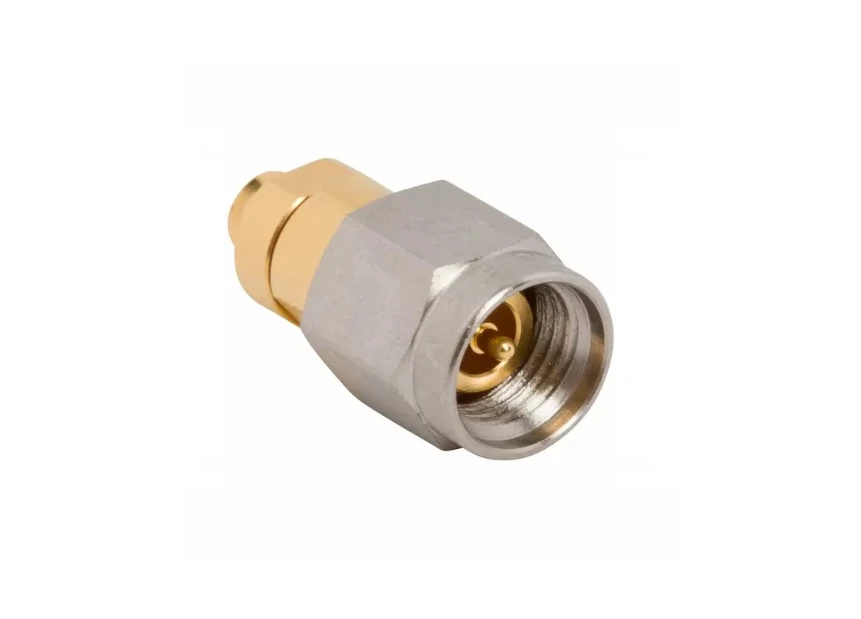
Detailed product image showing the thread and center-contact structure of an RP-SMA female interface. Buyers should inspect both features because an SMA and RP-SMA connector may appear mechanically compatible while the center contacts do not mate correctly.
A straight adapter is compact and keeps the interface count low. It works well when both ports are aligned, the attached cable is light, and there is enough axial clearance.
It becomes a poor choice when the feeder is stiff or the RP-SMA port is recessed.
A right-angle adapter can solve clearance problems, but its final direction is not always obvious from a product photo. Thread tightening changes orientation. Adjacent ports may interfere with the elbow body.
A pigtail provides routing freedom and mechanical isolation. It adds cable loss, so length and cable family matter.
A bulkhead transition is useful when the enclosure wall should carry the cable load or define the indoor-to-outdoor boundary.
| Installation Requirement | Straight Adapter | Right Angle | Flexible Pigtail | Bulkhead Transition |
| Aligned ports | Best fit | Optional | Suitable | Layout-dependent |
| Heavy feeder | Poor | Poor | Better | Best with support |
| Tight enclosure | Limited | Good | Good | Good |
| Vibration isolation | Low | Low | Better | Better |
| Custom routing | Low | Medium | High | High |
| Minimum interface count | Good | Good | Good | Layout-dependent |
| Defined outdoor boundary | SKU-dependent | SKU-dependent | Assembly-dependent | Preferred |
A straight adapter is not automatically the lowest-risk option. It may minimize RF interfaces while creating the highest mechanical stress.
The final architecture should be selected from both RF and mechanical requirements.
How Can You Remove N–SMA–RP-SMA Adapter Chains?
Adapter chains often grow one purchase at a time.
The installer has an N-to-SMA adapter in stock. A polarity changer is added later. A coupler is inserted because both ends have the same gender. The final path works on the bench, so it becomes the production solution.
A typical chain may look like this:
N Antenna→ N-to-SMA Adapter→ SMA Coupler→ SMA-to-RP-SMA Adapter→ Router Every added transition creates:
- Another mating interface
- Another contact pair
- Another possible loosened joint
- Additional mismatch
- Additional insertion loss
- More labeling risk
- More parts in the BOM
Then compare it with:
N Antenna→ Direct N-to-RP-SMA Adapter→ Router or:
N Antenna→ One-Piece N-to-RP-SMA Cable Assembly→ Router The RG cable guide can help when a one-piece cable assembly is being considered. Cable selection should account for attenuation, diameter, flexibility, and route length rather than connector names alone.
The best redesign is not always the one with the fewest metal bodies. If a direct rigid adapter overloads the radio port, a short pigtail may be the more reliable system despite adding cable length.
What Evidence Should the First Article Provide?
The first article should prove that the supplier and buyer are discussing the same interface.
Begin with identity checks:
- N-Type gender
- RP-SMA thread position
- RP-SMA center pin or socket
- Standard or reverse polarity
- Straight or right-angle body
- Overall dimensions
- Product marking
- Drawing revision
Then verify the DC path:
N center to RP-SMA center: Continuity required N shell to RP-SMA shell: Continuity required Center to shell: Isolation required
Move the adapter lightly during the continuity check. A marginal center contact can pass while stationary and open during handling.
RF testing should cover the actual operating band. Record:
- VNA calibration method
- Reference-plane location
- Sweep start and stop frequencies
- Return loss
- VSWR
- Insertion loss
- Sample identification
- Test fixture or mating cable
- Remating result
A single test at 2.4 GHz is insufficient for an assembly intended to support 2.4, 5, and 6 GHz operation.
Where vibration, temperature, or outdoor exposure matters, add those tests to the project plan rather than assuming that a bench RF sweep covers the field environment.
How Must the BOM and RFQ Name the Adapter?
The purchasing description should separate connector family, gender, polarity, orientation, and RF requirements.
A poor BOM note reads:
N to SMA Wi-Fi adapter
A usable BOM note reads:
Use the following RFQ block.
For repeat production, add:
- Approved drawing number
- Supplier part number
- Buyer part number
- Lot identification
- Inspection level
- Packaging quantity
- Change-notification requirement
A substitution that preserves the visible connector ends may still change the body length, plating, contact retention, dielectric, or measured RF response. The BOM should control the characteristics that matter to the application.
When Should You Avoid a Rigid N-to-RP-SMA Adapter?
Do not use a rigid adapter simply because it is the shortest option.
Avoid it when:
- The N-Type feeder is heavy
- The feeder exits sideways
- The RP-SMA port is PCB-mounted
- The radio enclosure provides weak connector support
- The equipment is moved frequently
- Vibration is present
- The ports are misaligned
- Weather sealing is required across an enclosure boundary
A short pigtail or panel-supported N-Type bulkhead can move the mechanical load away from the radio.
Also avoid an RP-SMA adapter when the installed device port is standard SMA. Reverse polarity is not an upgrade. It is a different interface configuration.
For standard SMA equipment, use a normal N-Type-to-SMA transition. The N-Type to SMA adapter guide covers that selection path.
A passive adapter should not be treated as an impedance transformer. If the two systems do not share the required impedance, selecting a mechanically compatible adapter does not correct the electrical mismatch.
Finally, use a purpose-built cable assembly when the installation requires:
- A long physical offset
- Flexible routing
- High vibration isolation
- Outdoor-to-indoor transition
- Panel sealing
- Strain relief
- Controlled cable length
- Permanent equipment integration
FAQ
Is an N-to-RP-SMA adapter electrically directional?
No. A passive straight-through adapter normally carries an RF signal in either direction. The naming order identifies the two connector interfaces. It does not define an input and output.
The installed ports determine the required genders. Buyers should describe both ends explicitly rather than relying on whether a listing says “N to RP-SMA” or “RP-SMA to N.”
Does RP-SMA female have a center socket?
No. Under the common RP-SMA convention, RP-SMA female has an internal thread and center pin. Standard SMA female has an internal thread and center socket.
This is why the thread alone cannot identify the interface. The center contact must also be inspected.
Can standard SMA be used when the RP-SMA threads engage?
No. Thread engagement does not prove correct center-contact mating. A standard SMA and RP-SMA combination may create two pins, two sockets, or marginal contact.
The result can be an open RF path, contact damage, intermittent signal, or poor RF performance.
Is every N to RP-SMA adapter automatically 50 ohms?
No. RP-SMA is commonly associated with 50-ohm wireless equipment, but the complete specification must still be confirmed. N-Type products also exist in different configurations.
The adapter, antenna, radio, feeder, and test equipment should all match the required system impedance.
Can the adapter improve Wi-Fi range?
No. An adapter does not add antenna gain. It changes the physical interface and introduces a passive transition.
Range depends on transmit power, receiver sensitivity, antenna gain, feeder loss, adapter loss, installation position, interference, and the complete link budget.
When is a pigtail safer than a rigid adapter?
A pigtail is safer when the N-Type feeder is heavy, the RP-SMA port is mounted directly to a PCB, the ports are offset, vibration is present, or routing requires a sharp change in direction.
The cable type and length still need to be selected for the operating frequency.
Which tests catch most first-article problems?
Check the connector gender, RP-SMA polarity, thread engagement, center continuity, shell continuity, center-to-shell isolation, return loss or VSWR, insertion loss, remating stability, dimensions, and body looseness.
For outdoor or mobile use, add the environmental and mechanical tests required by the project.
Final Buying Guidance
An N to RP-SMA adapter is a small part with several independent selection variables.
Before issuing the order, confirm:
N-Type gender RP-SMA gender RP-SMA center pin or socket Nominal impedance Operating frequency Maximum VSWR or minimum return loss Maximum insertion loss Orientation Overall length Indoor or outdoor location Cable weight and stiffness Mechanical support Required drawing and test evidence
Do not approve the adapter from its thread fit alone.
For a light, aligned, indoor connection, a direct rigid adapter may be the cleanest solution. For a heavy feeder, recessed port, vibrating assembly, or outdoor transition, a flexible pigtail or supported bulkhead is usually easier to control.
Send the supplier photographs of both installed ports, the required mating interfaces, operating band, feeder type, layout dimensions, and RF acceptance limits. That information is more useful than the phrase “Wi-Fi adapter,” and it gives both engineering and procurement teams a specification they can inspect.
