
An N-to-UHF connection often begins as a simple purchasing request: one device has an N-type port, another cable ends in PL-259, and a small adapter appears to solve the problem.
Then the adapter arrives and does not mate.
In other cases, it fits perfectly but places a heavy feeder cable directly on the radio port. The connection passes continuity, yet the antenna system shows a higher SWR than expected. A buyer may blame the adapter, although the real cause is an incorrect gender description, an unsupported cable load, an impedance problem, or several unnecessary transitions stacked together.
Selecting an N to UHFadapter requires more than matching two connector names. You need to identify the mating gender on both sides, distinguish PL-259 from SO-239, confirm the RF requirements, and decide whether a rigid adapter is mechanically safe.
Which N and UHF Ports Are You Trying to Connect?
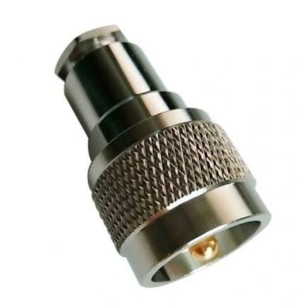
This image shows a straight N male to UHF female coaxial adapter with a knurled coupling body. Before installation, confirm the connector gender, system impedance, operating frequency, and mechanical load on the equipment port.
“Send an N-to-UHF adapter” is not a complete specification.
There are four basic gender combinations, and each produces a different part. Before checking frequency, plating, or price, identify the ports already installed on the equipment and cable.
Identify the N-type connector first
An N male normally has a center pin and a coupling nut with internal threads. An N female normally has a center receptacle and external coupling threads.
Do not identify the connector only from the center contact. Look at the complete mating interface:
- Center pin or center socket
- Internal or external coupling thread
- Cable-mounted or panel-mounted construction
- Equipment port or cable-end connector
- 50-ohm or 75-ohm specification
N-type connectors commonly appear on antenna systems, wireless equipment, RF instruments, outdoor feeders, repeaters, and higher-power radio equipment. That does not mean every N-type port has the same impedance or usable frequency range.
A 50-ohm N port and a 75-ohm N port may look similar enough to create a sourcing mistake. The specification, drawing, or equipment manual should settle the question.
For more detail on identifying the interface, see the N-Type Connector Guide.
Recognize PL-259 and SO-239 correctly
On the UHF side, the traditional connector pair is:
- PL-259: UHF male plug
- SO-239: UHF female socket
A PL-259 cable plug mates with an SO-239 socket. Two PL-259 connectors do not connect directly, and two SO-239 sockets require a male-to-male transition.
The word “UHF” causes additional confusion. In this context, UHF is the historical name of the connector family. It is not a guarantee that every connector sold under that name will perform well across the entire UHF radio-frequency band.
Mini-UHF is also a separate interface. It is not a smaller version that can mate with a standard PL-259 or SO-239.
Translate equipment ports into the adapter you must order
The adapter interfaces must be the opposite gender of the two ports being connected.
| Existing N-side port | Existing UHF-side port | Required adapter |
| N female | PL-259 male | N male to UHF female |
| N male | SO-239 female | N female to UHF male |
| N female | SO-239 female | N male to UHF male |
| N male | PL-259 male | N female to UHF female |
| Unknown | Unknown | Stop and verify with a drawing or clear photo |
The phrase N female to UHF male adapter should describe the adapter itself, not the ports installed on the equipment. This distinction matters when buyers, engineers, and suppliers use different naming habits.
A practical request should include photographs of both existing interfaces. One front view and one side view are usually more useful than a product name copied from an old purchase order.
Record these fields before releasing the order:
- Gender of each equipment port
- Connector family
- Center-contact style
- Coupling-thread structure
- Mounting style
- Final mating direction
Is UHF the Same as a High-Frequency UHF-Rated Connector?
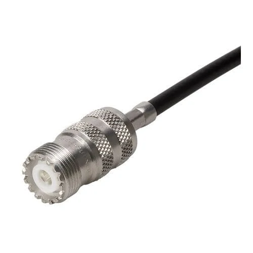
This image shows an SO-239 UHF female connector installed on a flexible black coaxial cable. A short cable assembly can reduce side loading and bending stress compared with attaching a long rigid adapter directly to the radio or instrument port.
No. The name and the electrical rating are separate matters.
The UHF connector family dates from an earlier period of radio engineering. PL-259 and SO-239 connectors remain common in amateur radio, CB radio, HF equipment, antenna tuners, meters, and some VHF installations. Their continued use does not make every UHF adapter a controlled-impedance microwave component.
A connector can mate mechanically and still create a visible discontinuity on a VNA sweep.
Check the adapter specification, not just its name
At minimum, request:
- Impedance
- Tested frequency range
- VSWR or return-loss limit
- Insertion-loss limit
- Power rating
- Body and contact materials
- Plating
- Environmental rating, where relevant
Avoid applying one universal frequency limit to every UHF adapter. Geometry, dielectric support, body construction, machining consistency, mating condition, and measurement method all affect the result.
A basic nickel-plated adapter intended for HF bench use should not automatically be substituted into a low-VSWR VHF or UHF measurement path. Conversely, an expensive precision transition provides little benefit if the cable, antenna, or termination already dominates the system loss.
Know when N-type is the safer RF interface
| Application | Practical interface preference | Higher-risk condition |
| HF amateur-radio station | PL-259/SO-239 remains common | Long or stacked |
| General VHF antenna connection | Check measured adapter and system performance | Heavy feeder |
| Higher-frequency outdoor feeder | N-type is usually the safer starting point | Large solid-center cable |
| Weather-exposed antenna port | Sealed N-type construction is commonly preferred | Unsupported lateral routing |
| Laboratory RF measurement | Select by test frequency and required repeatability | Vehicle, mast, or machinery |
| Legacy transceiver connection | UHF may be retained to avoid replacing equipment ports | Small PCB or thin panel |
| Final measurement | Confirm SWR or return loss in the installed system | Flexible jumper |
| Final decision | Review | Approve/Revise |
| Return loss | VNA | Project requirement |
| Insertion loss | VNA | Project requirement |
| Retention | Repeated mating | Pass or fail |
| Installed SWR | Actual antenna system | Recorded value |
| Final approval | Engineering review | Accept or reject |
The decision is not “N good, UHF bad.” It is whether the complete transition meets the operating band and measurement target.
The SMA to UHF Adapter Guide provides additional context on UHF gender naming and legacy radio interfaces without treating the UHF name as a frequency guarantee.
Does the N-to-UHF Adapter Keep a 50-Ohm RF System?
It can be used in a 50-ohm system, but the adapter does not create impedance matching.
A passive adapter changes the mechanical interface. It does not function as an impedance transformer, matching network, attenuator, or active compensation device.
Every part in the path still matters:
- Radio output
- N-type connector
- N-to-UHF adapter
- Coaxial cable
- Antenna feed point
- Couplers or lightning protectors
- Antenna matching network
Verify impedance across the complete path
Most amateur-radio antenna systems are designed around a nominal 50-ohm impedance. The N-type parts, cable, and equipment ports should therefore be specified accordingly.
UHF connectors require more care because their geometry is not a fully controlled constant-impedance transmission line. That does not prevent practical use, particularly at HF and in many VHF applications. It does mean that a “50-ohm” label should not replace actual RF verification where low VSWR is important.
Estimate a true impedance mismatch
This produces a return loss of approximately 14 dB and a VSWR of approximately 1.5:1 before cable loss, connector discontinuities, or antenna detuning are considered.
An adapter marked “50 ohm” cannot remove that mismatch. A real matching circuit or correctly designed transformer is needed.
Use a 50-ohm compatibility checklist
A continuity test cannot complete this checklist. It only confirms that the conductors are electrically connected.
When Should You Use a Rigid Adapter Instead of a Jumper?
A rigid adapter is compact, inexpensive, and easy to install. It is also a mechanical lever.
That second point is often ignored.
Connecting a heavy coaxial feeder through a long metal adapter transfers cable movement directly into the equipment port. A connector that survives for years on a fixed test bench may loosen or damage a panel when installed on a vibrating rack or outdoor radio.
Use a rigid adapter for short, supported connections
A rigid N type to UHFadapter is practical when:
- The connection is indoors
- The cable is light and flexible
- The adapter is supported
- The equipment remains stationary
- The connection is short
- Side loading is negligible
- Frequent movement is unlikely
Bench testing is a typical case. An adapter can connect an N-port instrument to a PL-259 cable without requiring a dedicated jumper for every temporary setup.
Choose a jumper when the cable creates stress
A short N-to-UHF cable assembly is safer when the installation includes:
- Heavy RG8, RG213, LMR-400, or similar feeder
- A fragile radio or instrument port
- Vibration
- Repeated equipment movement
- Side pull
- Tight cabinet routing
- Outdoor installation
- Limited panel strength
The jumper moves the heavy-cable transition away from the equipment connector. It also allows proper strain relief and a controlled bend radius.
Calculate the port-loading risk
A simplified bending-moment estimate is:
Where:
- (M) is the bending moment at the equipment port
- (F) is the cable load or side force
- (d) is the distance from the port to where that force acts
A longer adapter increases (d). A heavier or stiffer cable increases (F). The resulting port load can rise even though the adapter itself weighs very little.
Which Antenna and Radio Applications Need This Transition?
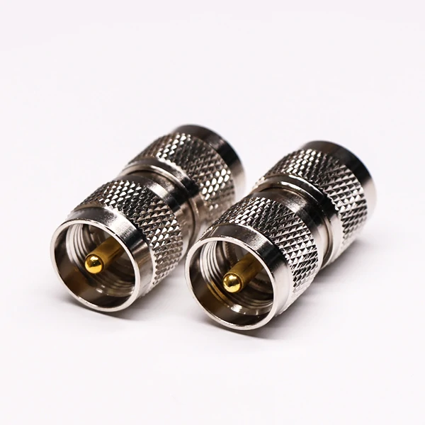
The image shows two straight UHF male-to-male adapters with PL-259-style interfaces. This configuration can bridge two SO-239 female connectors, but the complete signal path should still be checked for impedance, frequency, and mechanical support.
N-to-UHF transitions are most useful when two generations or classes of RF hardware must work together.
A modern outdoor antenna may use an N-type connector for mechanical strength and weather resistance. The transceiver, tuner, power meter, or legacy feeder may still use PL-259 and SO-239.
Bridge modern antenna hardware and legacy radio equipment
Common applications include:
- Amateur-radio transceivers
- Base-station antennas
- Repeaters
- Antenna analyzers
- RF power and SWR meters
- Feed-line test equipment
- Antenna tuners
- Custom laboratory fixtures
- Temporary field-radio installations
An N to PL259 adapter may be used where an N-type antenna or instrument must connect to a cable terminated with a PL-259 plug. The adapter configuration still depends on the exact N-side gender.
Use the actual system during approval
An adapter that performs acceptably with a short bench cable may behave differently after installation.
The final setup can add:
- Longer cable
- Smaller bend radius
- Water ingress risk
- Lightning protection
- Grounding hardware
- Cable movement
- Antenna detuning
- Additional couplers
For an antenna analyzer or low-power test instrument, compare the adapter against a known reference connection. For a transmitter, check the installed SWR at the intended power level while following the radio and antenna manufacturers’ operating limits.
Do not use the adapter as an antenna-matching device
An adapter cannot correct:
- An antenna cut for the wrong band
- A damaged feed line
- Incorrect cable impedance
- Poor grounding
- Water inside the connector
- An unsuitable balun or matching network
- Excessive connector loss
- A high-SWR antenna installation
If the SWR is already high, adding an adapter may slightly change the reading, but it does not repair the underlying problem.
How Do You Avoid Adding Too Many RF Interfaces?
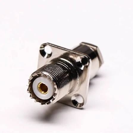
This is a panel-mount SO-239 UHF female connector with a four-hole square flange. The flange supports secure installation on radio equipment, test fixtures, antenna systems, and custom RF enclosures.
Adapter stacks are easy to build because each additional part solves one immediate mechanical problem.
The final path may look like this:
N antenna→ N-to-UHF adapter→ UHF barrel coupler→ PL-259 jumper→ another adapter→ radio The signal may pass, but the chain now contains several contact pairs, threaded joints, and possible weather-entry points.
A cleaner path is:
N antenna→ correctly configured N-to-UHF cable assembly→ radio Or, where the equipment is directly adjacent and mechanically supported:
N antenna port→ one N-to-UHF adapter→ radio port
Estimate the complete insertion loss
A simple path budget is:
The “other” term may include switches, lightning protectors, filters, meters, or poorly characterized couplers.
Do not assign a universal loss figure to every adapter. The result changes with frequency, construction, mating condition, and test method. Use supplier data when available, then verify samples when the remaining link margin is small.
Connector count also affects maintenance. Every exposed joint can loosen, oxidize, collect contamination, or admit moisture.
Simplify the path before approving the BOM
Record:
The RF Adapter Guide is useful when the signal path includes other transitions such as N-to-SMA, N-to-BNC, or reverse-polarity interfaces.
How Should Samples Be Tested Before Approval?
A sample should be checked mechanically, electrically, and inside the intended RF system.
Passing only one of those stages is not enough.
Verify mechanical compatibility
Inspect:
- Correct N gender
- Correct UHF gender
- Full thread engagement
- Smooth coupling
- Center-contact alignment
- No loose body sections
- No damaged plating
- No burrs or metal debris
- Suitable body length
- Adequate wrench or finger clearance
Do not force a connector that becomes tight after only partial engagement. Cross-threading can damage both the adapter and the equipment port.
Verify continuity and isolation
Use a digital multimeter to confirm:
- Center contact to center contact: continuity
- Outer conductor to outer conductor: continuity
- Center contact to outer body: isolation
A continuity result does not confirm impedance, insertion loss, or return loss. It is only the first electrical screening step.
Measure RF performance where the application requires it
A VNA test should use suitable calibration, fixtures, and reference adapters. Record:
- Test-frequency range
- VSWR
- Return loss
- Insertion loss
- Port configuration
- Calibration plane
- Sample quantity
- Repeat-mating result
For production approval, test more than one “golden” sample. A single carefully selected part does not show batch consistency.
Test repeated mating and the actual antenna path
Mate and unmate the adapter several times, then repeat the measurement. Large variation may indicate unstable contact pressure, loose construction, contamination, or inconsistent mating torque.
A practical acceptance record can use the following structure:
What Should Be Written in the Purchase Specification?
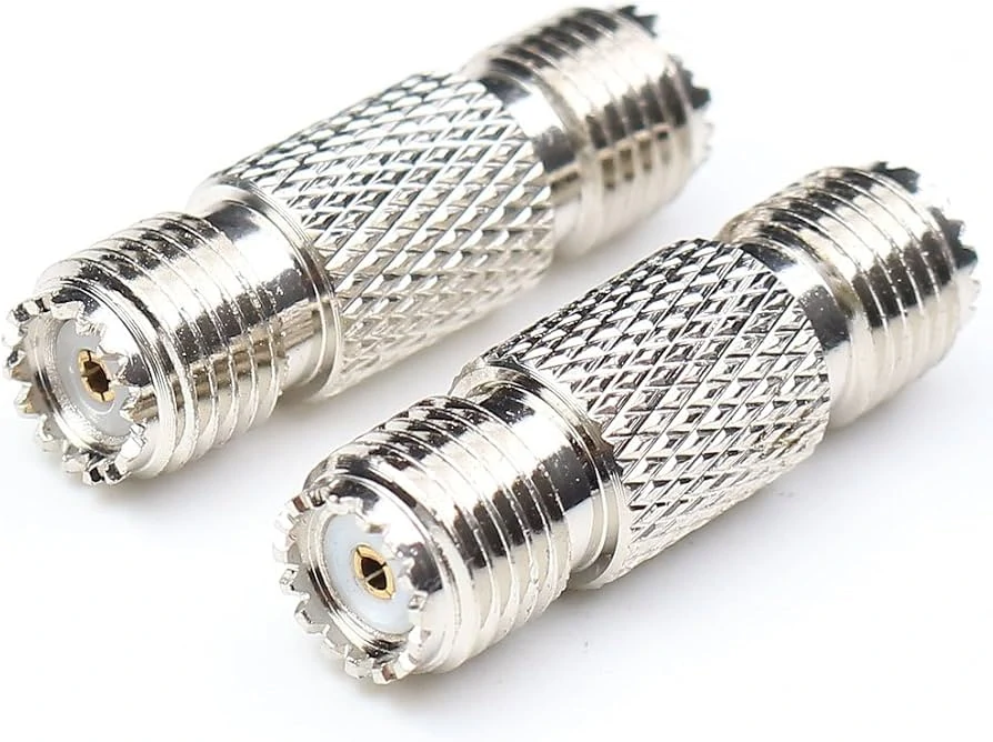
The image shows two straight UHF female-to-female barrel adapters with SO-239 interfaces. These couplers can connect two PL-259 cable plugs, although each additional adapter introduces another contact pair and possible maintenance point.
A clear purchase specification separates the interface description from the RF and mechanical requirements.
Do not write:
N-UHF adapter
That description leaves the supplier to guess the gender, impedance, body arrangement, and application.
A better basic description is:
N Female to UHF Male Adapter 50 Ohm Straight Body Indoor Ham-Radio Application
Define both connector sides
State:
- N male or N female
- UHF male/PL-259 or UHF female/SO-239
- Straight or right-angle body
- Rigid adapter or flexible cable assembly
- Cable or panel mounting, where applicable
Include a drawing when body length, panel clearance, thread engagement, or surrounding hardware is restricted.
Separate RF requirements from mechanical requirements
RF requirements
- Nominal impedance
- Operating-frequency range
- Required VSWR
- Required return loss
- Maximum insertion loss
- Power requirement
- Test method
- Required test report
Mechanical and environmental requirements
- Connector gender
- Body style
- Body material
- Contact material
- Plating
- Insulator
- Thread requirement
- Waterproofing
- Temperature requirement
- Vibration requirement
- Mating-cycle requirement
“Gold plated” is not a complete specification. Clarify whether the requirement applies to the center contact, body, or both.
Use this RFQ template
For a broader connector-family comparison, the RF Connector Guide can help procurement teams decide whether retaining UHF is practical or whether a direct N-type cable assembly is the cleaner long-term solution.
FAQ
Is an N-to-UHF adapter used only for amateur radio?
No. Amateur radio is a common application because many transceivers, meters, tuners, and feed lines use PL-259 or SO-239. The same transition may also appear in antenna testing, communication equipment, RF measurement fixtures, repeaters, and temporary field systems. Suitability still depends on the operating frequency, impedance, required RF performance, and mechanical installation.
Does an N-to-UHF adapter improve antenna performance?
No. The adapter changes the connector interface. It does not tune the antenna or correct impedance mismatch. Antenna performance depends on the antenna design, operating band, cable loss, connector condition, grounding, feed-point matching, and installation. An unsuitable adapter can make results worse, but a suitable adapter does not improve a poorly tuned antenna.
Can a PL-259 cable connect directly to an N connector?
No. PL-259 and N-type connectors have different dimensions, threads, and contact geometry. They require a correctly configured adapter or a dedicated cable assembly. Before ordering, confirm whether the N port is male or female. Saying only “PL-259 to N adapter” does not fully define the required part.
Why is N-type generally preferred at higher frequencies?
N-type connectors provide a more controlled coaxial geometry than the traditional UHF connector family. They are also available in mechanically strong and weather-sealed constructions. Actual performance still depends on the specific connector, manufacturing quality, mating condition, cable, and test frequency. Do not rely only on the connector-family name.
Can a 50-ohm N connector connect to any UHF connector?
Not automatically. Confirm the intended impedance and operating frequency of the full path. A passive adapter does not convert 50 ohms to 75 ohms or repair an antenna mismatch. When the system has a strict return-loss requirement, test the actual adapter and cable combination rather than relying only on catalog wording.
When should I use an N-to-UHF cable instead of a rigid adapter?
Use a flexible cable assembly when the feeder is heavy, the equipment port is fragile, the installation vibrates, or the cable must turn immediately after the connector. A short jumper reduces leverage at the port and allows better strain relief. A rigid adapter is better reserved for supported, short, stationary connections.
What should be tested before installation?
Confirm connector gender, thread engagement, center-contact alignment, continuity, isolation, impedance, and mechanical retention. For frequency-sensitive work, measure VSWR, return loss, and insertion loss. The final check should be made in the actual antenna system because cable routing, additional accessories, weatherproofing, and antenna tuning can change the result.
An N-to-UHF adapter is a useful transition when the interface direction, RF limits, and mechanical load are known. Before ordering, send the supplier clear port photographs, gender information, operating frequency, impedance, cable type, application environment, and test requirement. Those details are more valuable than the connector-family name alone.
For neutral technical reference, buyers can also consult the Amphenol RF N-Type connector information and the ARRL coaxial connector reference.
