
How Should You Select a BNC Adapter for an RF System?
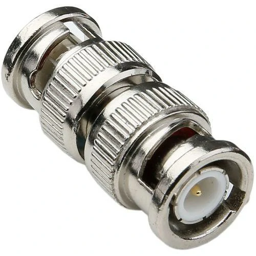
Close-up image of a BNC female-to-female coaxial adapter. This straight barrel adapter can join two BNC male connectors and is commonly used for cable extension, RF testing, signal measurement, and temporary laboratory connections.
In many RF test setups, the connection problem appears before the signal problem.
A signal generator may use a BNC port, while the device under test uses an SMA interface. A measurement cable may already be installed with one connector type, but the instrument available in the laboratory requires another. In these situations, replacing the whole cable assembly is often unnecessary. A suitable BNC adapter can provide a practical connection solution.
Although a BNC adapter looks like a simple mechanical part, its role in an RF path should not be overlooked. The adapter becomes part of the transmission line after installation. Its connector design, contact quality, and impedance matching can influence the final measurement result.
When selecting a BNC adapter, engineers normally check several points:
- Interface type and connection direction
- Male or female configuration
- 50Ω or 75Ω impedance
- Operating frequency
- Installation space
- Required RF performance
A correct selection helps maintain a stable connection. A wrong choice may cause unexpected problems during testing, especially when the system operates at higher frequencies.
Why Does a BNC Adapter Matter in RF Connection Design?
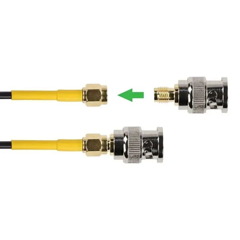
BNC connectors have been used in electronic measurement applications for many years because of their convenient locking structure.
For example:
- An oscilloscope may provide a BNC input.
- An RF module evaluation board may use SMA connectors.
- A coaxial cable assembly may have another interface requirement.
Instead of preparing a separate cable for every combination, adapters allow engineers to reuse existing equipment.
However, adding an adapter also adds another transition point in the RF chain. Each transition has the possibility of affecting signal behavior.
The main factors engineers pay attention to include:
- Impedance continuity
- Contact reliability
- Mechanical fit
- Signal reflection
- Additional insertion loss
For systems involving RF measurements, the adapter should be considered together with the cable and connected equipment. A high-quality connector cannot compensate for an incorrect impedance match elsewhere in the signal path.
Before selecting an adapter, many engineers first review the complete connection structure, including the cable type and interface requirements. TEJTE also provides related information about RF adapter selection guide to help compare different connector conversion solutions.
How Can You Identify the Right BNC Adapter Specification?
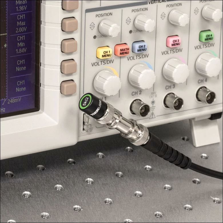
BNC adapter installed on an oscilloscope input with a coaxial test cable. This type of connection is used for waveform testing, signal monitoring, impedance verification, and electronic laboratory measurements.
Choosing a BNC adapter usually starts with the physical connection, but the electrical requirements decide whether the adapter is suitable for the application.
Check the connector interface first
The first step is confirming what needs to be connected.
Common BNC adapter combinations include:
- BNC male to female
- BNC female to female
- BNC male to male
- BNC to SMA
- BNC to N type
Different structures solve different connection problems.
For instance, a BNC female to female adapter is often used when two BNC male cables need to be connected together. A BNC to SMA adapter is more suitable when traditional test equipment needs to connect with compact RF modules.
The interface direction should always be confirmed before ordering. A connector that looks similar may not provide the correct mating structure.
Check impedance before connecting RF equipment
One of the most important specifications of a BNC adapter is impedance.
BNC products are commonly available in:
- 50 ohm versions
- 75 ohm versions
The two versions may look almost identical from the outside, but they are designed for different systems.
50Ω BNC adapters are commonly used in:
- RF test equipment
- Wireless communication systems
- Signal measurement applications
75Ω BNC adapters are more common in:
- Video systems
- Broadcast equipment
- Some transmission applications
Using an adapter with the wrong impedance can create signal reflection. In measurement environments, this may appear as unstable readings or unexpected RF performance changes.
For RF systems, impedance matching should always be checked together with the cable and equipment specifications.
RF module testing
Many modern RF modules use smaller connectors such as SMA because of space limitations. However, development equipment may still rely on BNC interfaces.
A BNC adapter allows these different systems to work together during:
- Prototype evaluation
- Signal testing
- Design verification
In this type of application, connector conversion is not only a mechanical requirement. Maintaining signal quality through the adapter is equally important.
BNC Adapter Basic Selection Reference Table
| Adapter Structure | Connection Purpose | Common Usage |
| BNC Male to Female | Change connection direction or extend interface | Equipment connection |
| BNC Female to Female | Join two BNC male cables | Cable extension |
| BNC Male to Male | Connect two BNC female ports | Test setup |
| Right Angle BNC Adapter | Reduce cable bending space | Compact installation |
| Bulkhead BNC Adapter | Panel mounting connection | Equipment enclosure |
| BNC Tee Adapter | Add measurement point | Signal monitoring |
This basic selection table can help narrow down the suitable structure before checking detailed RF specifications.
When Should You Use a BNC to SMA Adapter?
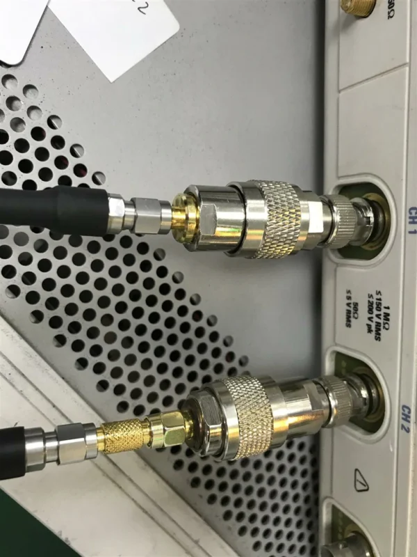
In many RF laboratories, the equipment and the device under test do not always use the same connector.
A signal generator may come with a BNC output. The RF board being tested may only provide an SMA port. A cable already prepared for one project may not match the connector used in another project.
This is where a BNC to SMA adapter becomes useful.
Instead of preparing a new cable assembly, the adapter creates a connection between the existing BNC equipment and SMA devices. It is a small component, but it can save time during development, debugging, and production testing.
A typical application may involve:
- Connecting a BNC oscilloscope input to an SMA cable
- Linking laboratory equipment with RF modules
- Testing antenna interfaces
- Building temporary measurement setups
The important point is that the adapter is not only a mechanical converter. Once installed, it becomes part of the RF signal path.
How Do BNC and SMA Interfaces Create Different Adapter Requirements?
BNC and SMA connectors are often seen together in RF work, but they come from different application environments.
BNC was designed for fast connection.
Common SMA applications include:
- Wireless modules
- Antenna connections
- RF evaluation boards
- Microwave components
When a BNC device needs to communicate with an SMA device, the adapter has to handle both sides correctly.
The mechanical connection is only the first check.
The electrical side also matters:
- Is the impedance matched?
- Is the frequency range suitable?
- Does the adapter maintain acceptable RF performance?
A connector transition that works well at a lower frequency may not provide the same result in a more demanding RF application.
What Should You Check Before Ordering a BNC to SMA Adapter?
Many adapter selection mistakes happen because the product name looks correct, but one specification does not match the actual requirement.
Confirm the connector gender
BNC to SMA adapters are available in different combinations.
For purchasing teams, providing a connector drawing or a photo of the existing interface can often avoid unnecessary communication problems.
Check the impedance of the whole connection
RF systems normally require impedance consistency.
A BNC interface can exist in both 50Ω and 75Ω versions.
The connector appearance may look similar, but the application is different.
50Ω systems are commonly used for:
- RF testing
- Wireless communication
- Antenna measurement
- Signal analysis
75Ω systems are more common in:
- Video equipment
- Broadcast applications
Using the wrong impedance adapter may introduce reflection into the transmission path.
In practical testing, this may appear as:
- Unstable measurement values
- Higher VSWR
- Reduced repeatability
This is why RF engineers normally check the cable, adapter, and equipment specifications together.
Consider frequency requirements
Frequency is another factor that cannot be ignored.
A BNC to SMA adapter used for general electronic testing may have different requirements from one used in RF measurement equipment.
When the working frequency increases, small differences in:
- Contact design
- Material quality
- Internal structure
- Manufacturing accuracy
can affect the signal.
For applications involving precise measurement, parameters such as VSWR and return loss should also be considered.
How Are 50Ω and 75Ω BNC Adapters Selected?
One common misunderstanding is assuming every BNC adapter can be used in every BNC system.
The connector interface may be identical, but the electrical design can be different.
50Ω and 75Ω BNC Adapter Comparison
| Item | 50Ω BNC Adapter | 75Ω BNC Adapter |
| Main Application | RF testing and communication | Video and broadcast |
| System Impedance | 50 ohm | 75 ohm |
| Common Equipment | RF instruments | Video equipment |
| Main Concern | Signal reflection | Signal transmission quality |
| Typical Use | RF connection | Video connection |
For RF applications, 50Ω matching is normally the expected choice.
A mismatch does not always cause an immediate connection failure. The problem usually appears in the electrical performance of the system.
During measurement work, even a small reflection introduced by an unsuitable adapter can affect test accuracy.
How Does a BNC Tee Adapter Help During Testing?
A standard adapter connects two interfaces.
A BNC Tee adapter has another purpose — it creates an additional connection point.
This structure is useful when a technician needs access to an existing signal without removing the original connection.A Tee adapter provides a practical way to add that measurement point.
The additional branch also creates another transition in the RF path.
For low-frequency applications, this may have little influence.
For sensitive RF measurements, the extra connection should be evaluated carefully.
Important points include:
- Operating frequency
- Adapter quality
- Cable arrangement
- Measurement accuracy requirement
BNC Tee Adapter Selection Reference
| Application Situation | Suitable Choice |
| Need temporary signal access | BNC Tee adapter |
| Need quick equipment switching | Standard BNC adapter |
| Need panel installation | Bulkhead adapter |
| Limited installation space | Right-angle adapter |
| High-frequency measurement | Reduce unnecessary transitions |
A BNC adapter is a practical solution for many RF connection problems, but the best choice depends on the complete application environment.
How Can You Avoid Problems When Selecting BNC Adapters?
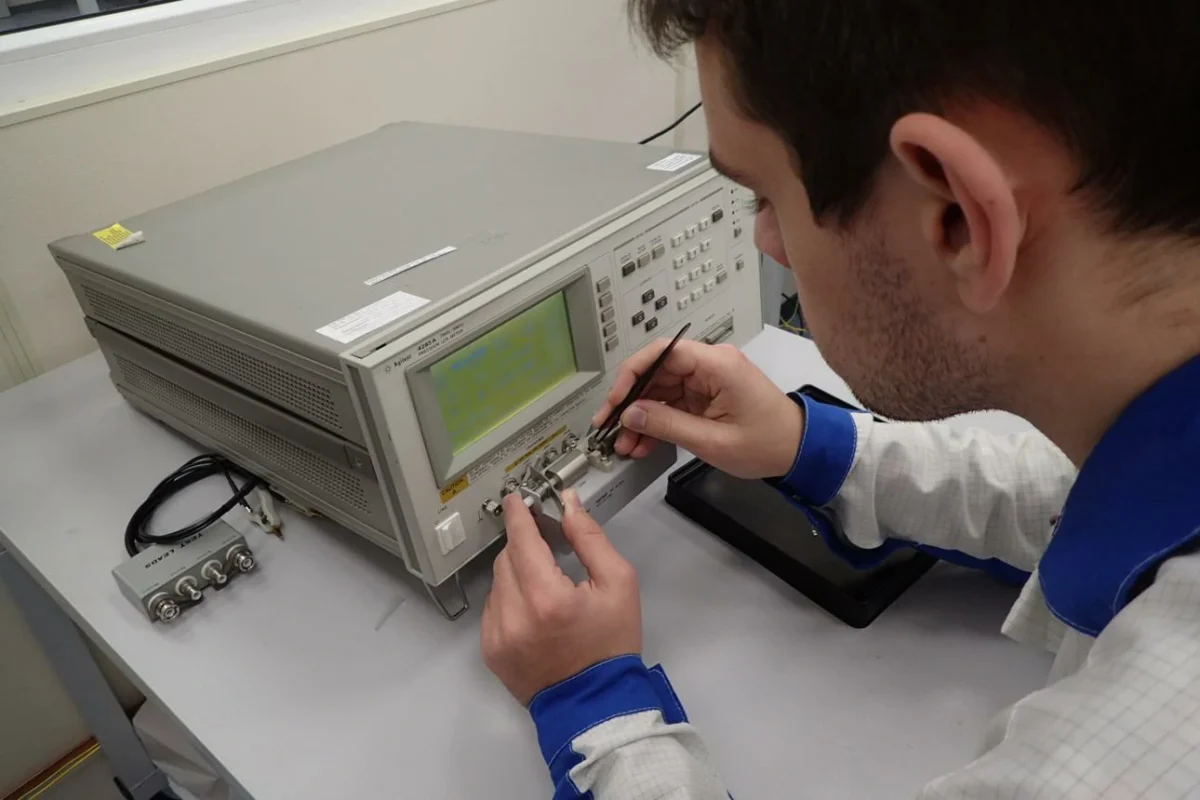
A BNC adapter is usually not the first component people think about when building an RF connection.
Most attention goes to the instrument, cable, or device under test. The adapter is often added at the last step when two interfaces do not match.
This is also where many connection problems start.
A connector may fit mechanically, but that does not always mean it is suitable for the RF system.
For example, a BNC adapter used between a signal generator and a test cable may work normally during basic testing. The same adapter may create unexpected changes when the setup moves to higher-frequency measurements.
Before using a BNC adapter in an RF system, it is worth checking a few basic details:
- What connector interfaces are being connected?
- Is the adapter used temporarily or installed for long-term operation?
These questions are simple, but they prevent many unnecessary replacements later.
What Should Be Checked During BNC Adapter Testing?
A BNC adapter does not work independently.
Its performance depends on the equipment, cable, and other connectors connected around it.
A practical inspection normally starts from the physical side.
Mechanical inspection
The first check is usually appearance and fitting.
Common points include:
- BNC locking movement
- Connector alignment
- Contact condition
- Housing damage
- Surface finish
A loose connection may not always cause a complete signal failure. Sometimes it appears as unstable measurements or intermittent contact.
This is especially noticeable in test environments where cables are frequently connected and removed.
Electrical verification
For RF applications, mechanical checking is only the beginning.
Depending on the project requirement, users may check:
- VSWR
- Return loss
- Insertion loss
- Frequency response
A simple continuity test can confirm whether the signal path is connected.
It cannot show whether the adapter maintains good RF performance.
When the adapter is used with measurement equipment, testing the complete assembly often gives more useful information than testing the adapter alone.
How Do Additional Adapters Change an RF Signal Path?
In real projects, one adapter is sometimes not enough.
A test setup may include:
Instrument → Adapter → Cable → Adapter → Device
Every added connection creates another transition.
At lower frequencies, the influence may be small.
At higher frequencies, small differences in connector structure and contact quality become easier to notice.
In many situations, they are the fastest and most practical solution.
The key is keeping the connection path reasonable.
If a direct cable can solve the problem, adding multiple adapters may not provide much value.
Which RF Parameters Matter When Choosing a BNC Adapter?
VSWR
VSWR is commonly used to check whether the connection introduces significant reflection.
A poor transition between components can increase mismatch and affect measurement accuracy.
Return Loss
Return loss shows how much RF energy is reflected back toward the source.
It is often reviewed together with VSWR when evaluating connector transitions.
Insertion Loss
Insertion loss describes the signal loss through the connection.
For a single adapter, the effect may be limited.
For systems containing several adapters and cables, total loss becomes more important.
For users comparing RF connection performance, TEJTE also provides related technical information about RF adapter return loss measurement and signal evaluation methods.
How Should Buyers Communicate BNC Adapter Requirements?
A quotation request with only “BNC adapter” usually leaves many details unclear.
Different customers may mean completely different products:
- BNC to SMA adapter
- BNC to N adapter
- BNC female adapter
- BNC Tee adapter
- Bulkhead BNC adapter
Providing the application information first usually makes supplier communication easier.
A practical request may include:
- Existing equipment interface
- Required adapter structure
- Connector gender
- Impedance
- Frequency range
- Expected quantity
For custom projects, additional information can include:
- Installation environment
- Mechanical dimensions
- RF test requirements
The more complete the initial information is, the easier it is to confirm the correct product.
Where Are BNC Adapters Still Used Today?
Although many modern RF devices use smaller connector families, BNC adapters remain common in many existing systems.
Measurement equipment
BNC interfaces are still widely found on:
- Oscilloscopes
- Signal generators
- Counters
- Laboratory instruments
Adapters help connect older equipment with newer RF components.
Product development
During prototype stages, connector selection may change several times.
Using adapters allows engineers to continue testing without immediately changing cables or modifying hardware.
This flexibility is one reason BNC adapters continue to be used in development environments.
FAQ
I have BNC equipment but my cable uses SMA. What can I do?
A BNC to SMA adapter can be used to connect the two interfaces.
My equipment connection is loose. Should I change the adapter?
Check the connector type first. A wrong mating structure may cause poor contact.
Can this adapter be used in a test setup?
Yes, BNC adapters are commonly used with laboratory instruments and RF testing equipment.
