
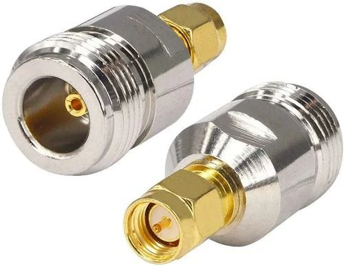
Pair of straight coaxial adapters featuring an N female interface and an SMA male interface. These RF adapters are suitable for antenna testing, wireless communication equipment, laboratory instruments, and coaxial connector conversion
During RF system development, connector mismatch happens more often than many engineers expect.
A new antenna may come with an N connector, while the existing test cable in the laboratory uses SMA. A communication device may already have a fixed interface, but the selected cable assembly does not match. Replacing the complete cable or redesigning the interface is usually unnecessary.
In these situations, an RF adapter provides a practical connection solution.
But there is one detail that is easy to overlook.
An adapter is not only a mechanical part. In an RF transmission path, every additional connection may influence electrical performance. The internal contact design, impedance control, and machining accuracy can affect signal reflection and transmission loss.
For low-frequency applications, these differences may not be obvious. As frequency increases, however, the adapter becomes an important part of the RF chain.
How Should You Select an RF Adapter for a Coaxial System?
The right RF adapter usually starts with understanding the actual connection requirement.
These details determine whether a standard adapter is suitable or whether a customized solution is needed.
For example, connecting a laboratory instrument to an antenna cable may only require a simple connector conversion. However, a microwave test system operating at higher frequencies requires more attention to adapter specifications, because small mechanical differences can influence measurement results.
A good selection process normally considers both sides of the connection:
Mechanical side
- Connector series
- Male or female interface
- Installation method
- Available space
Electrical side
- Impedance
- Frequency range
- VSWR
- Insertion loss
A connector that fits physically does not always mean it is the correct RF solution.
Check the Connector Interface Before Choosing an Adapter
The first thing to confirm is the connector family.
Common RF connector systems include:
- SMA
- N Type
- BNC
- TNC
- MMCX
- MCX
- SMP
Each connector has its own application background.
When two different connector systems appear in one project, an RF adapter becomes the connection bridge.
For example:
An antenna cable with an N male connector may need to connect to a measurement device using an SMA female port. An N to SMA adapter can complete this transition without replacing the existing cable.
This type of solution is common during:
- Prototype testing
- Equipment upgrades
- RF verification
- Antenna replacement
Why Does Adapter Gender Matter in RF Connections?
Many installation problems come from overlooking connector gender.
RF adapters are available in different combinations:
- Male to male
- Male to female
- Female to female
The center contact structure is different between male and female connectors.
A male connector normally contains a center pin, while a female connector provides the receiving contact.
Choosing the wrong combination may result in:
- Unable to connect
- Additional adapter requirements
- Incorrect mechanical fit
For example, an N female adapter is often used when connecting to an N male cable. If the equipment side already has an N female port, the selected adapter needs to provide the correct opposite interface.
This seems like a simple detail, but it becomes important when systems contain multiple cables and adapters.
Consider Adapter Structure Before Installation
The physical shape of an adapter also affects how easily it can be installed.
A straight RF adapter is commonly selected for general connections where enough space is available.
A right-angle adapter can be useful when:
- Equipment panels are crowded
- Cable bending needs to be reduced
- The installation depth is limited
For fixed equipment panels, a bulkhead adapter provides another option.
A bulkhead design allows the connector to pass through a mounting panel and remain fixed in position. This structure is often used in:
- Enclosures
- Test panels
- Communication equipment
The best structure depends on the installation environment, not only the connector specification.
How Do Coaxial Adapters Fit Different RF Connector Systems?
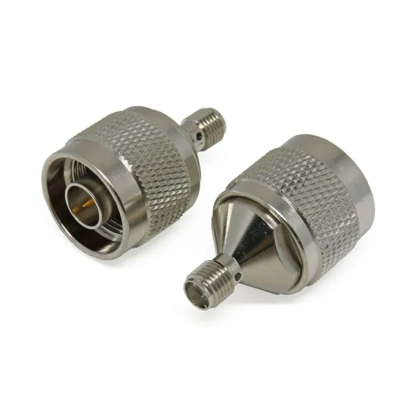
A coaxial adapter is widely used in RF applications where different coaxial interfaces need to be connected.
In practical projects, engineers rarely work with only one connector standard.
A wireless system may include:
- Antenna connector
- RF cable assembly
- Test interface
- Module connection port
Different components may use different connectors because each connector family has its own advantages.
The role of a coaxial adapter is to maintain the connection between these different parts.
Selecting Coaxial Adapters Based on Application
SMA Adapter
SMA adapters are often used in compact RF systems.
They are commonly used in:
- Embedded wireless products
- Small antenna modules
- Space-limited devices
Coaxial Adapter Selection Matrix
| Adapter Type | Common Application | Selection Focus |
| SMA Adapter | RF modules, test systems | Compact size, frequency capability |
| N Adapter | Antenna and communication equipment | Mechanical strength, outdoor use |
| BNC Adapter | Laboratory measurement | Fast connection |
| TNC Adapter | Industrial RF equipment | Threaded stability |
| MMCX Adapter | Compact wireless devices | Space limitation |
How Do RF Adapter Structures Change the Connection Method?
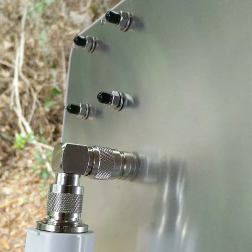
Close-up of a right-angle coaxial RF adapter connected to an outdoor metal equipment panel. The angled structure supports compact cable routing, reduces excessive cable bending, and provides a stable RF connection.
In many RF projects, the connector choice is decided before the equipment is installed. The problem usually appears later, when engineers start assembling cables and discover that the available space does not match the original design.
A connector may be technically correct but impossible to install because the cable has no room to bend. A straight adapter may extend too far from the equipment panel. A fixed device interface may need a stronger mounting method.
This is why RF adapter structure matters.
Two adapters may have the same connector combination but work very differently in the actual system.
For example, an SMA male to SMA female adapter and a right-angle version may provide the same electrical connection, but the installation result can be completely different inside a compact RF module.
Straight Adapter or Right-Angle Adapter: Which One Fits Your Installation?
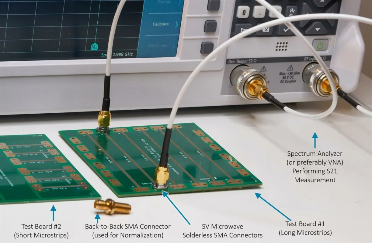
A straight adapter is usually the first option engineers consider.
The reason is simple: the signal path is direct, the mechanical structure is straightforward, and it works well for general connections.
However, equipment design is not always that convenient.
Inside a communication device or test fixture, the connector may be close to a housing wall or another component. Forcing a cable into that position can create unnecessary stress on the connector.
This is where a right-angle RF adapter becomes useful.
A 90-degree structure changes the cable direction immediately after the connector. It helps reduce:
- Cable bending radius problems
- Mechanical pressure on the connector
- Installation space requirements
For compact assemblies, the physical layout sometimes decides the adapter structure before electrical specifications do.
When Does a Bulkhead Adapter Become a Better Choice?
A normal adapter relies on the connected cable and equipment port for support.
A bulkhead adapter is different.
It is designed to be fixed through a panel, enclosure, or mounting plate. The connector becomes part of the equipment structure instead of remaining a loose connection point.
This design is commonly seen in:
- RF test panels
- Communication cabinets
- Outdoor equipment boxes
- Custom electronic enclosures
For example, an equipment manufacturer may need an external RF port on the housing. Instead of leaving a cable passing through the enclosure, a bulkhead N adapter can create a fixed connection interface.
This improves installation consistency and makes repeated connection easier.
When selecting a bulkhead adapter, engineers usually check:
- Panel thickness compatibility
- Mounting hole size
- Connector orientation
- Environmental requirements
The mechanical details are just as important as the RF specifications.
RF Adapter Structure Decision Table
| Structure | Suitable Situation | Selection Point |
| Straight Adapter | General cable connection | Simple installation |
| Right Angle Adapter | Limited installation space | Reduce cable bending |
| Bulkhead Adapter | Equipment panel mounting | Fixed connector position |
| Tee Adapter | RF testing and monitoring | Additional measurement access |
| Gender Adapter | Interface conversion | Solve connector mismatch |
When Should You Use an N Type Adapter?
The engineer needs to confirm:
- N male or N female interface
- Straight or bulkhead structure
- Operating frequency
- Impedance requirement
- Installation environment
How Do N Male Adapter and N Female Adapter Differ?
The difference between N male adapter and N female adapter comes from the contact structure.
An N male interface uses a center pin.
An N female interface uses a socket contact.
This difference determines how two components connect.
For example:
An RF cable with an N male connector needs a compatible N female interface. If both sides are male, an additional adapter configuration is required.
| Interface | Contact Style | Common Situation |
| N Male | Pin contact | Cable connection side |
| N Female | Socket contact | Equipment interface side |
In practical RF projects, checking gender before ordering can avoid unnecessary replacement or additional conversion parts.
This is especially important for large installations where hundreds of cable connections may be involved.
How Can N to SMA Adapters Connect Different RF Systems?
Different RF equipment manufacturers often use different connector standards.
Antenna systems commonly use N connectors because of their robust structure.
Test equipment often uses SMA connectors because they are compact and suitable for measurement applications.
This creates a common connection requirement:
N interface equipment + SMA interface equipment
An N to SMA adapter solves this type of interface difference.
Typical applications include:
- Antenna measurement
- RF prototype testing
- Wireless module evaluation
- Laboratory equipment connection
For example, an engineer may need to connect an N type antenna cable to a VNA test port using SMA. The adapter allows the measurement to proceed without changing the original cable assembly.
But the adapter should still match the RF requirements of the system.
Important specifications include:
- 50 ohm impedance
- Frequency range
- VSWR
- Insertion loss
A simple mechanical connection is not enough for accurate RF testing.
How Does Impedance Influence RF Adapter Selection?
Impedance problems are often invisible during installation.
The connector may appear correctly installed, but the RF performance can still be affected.
Most RF systems are based on a 50 ohm environment.
This can influence:
- VSWR results
- Return loss performance
- Measurement repeatability
Why Should Frequency Range Be Checked Before Ordering?
A connector series does not automatically define the complete RF capability.
Two adapters with the same connector type may have different frequency performance because of:
- Internal structure
- Material selection
- Manufacturing accuracy
- Contact design
For example, an adapter used in a basic wireless system may have very different requirements from one used in microwave testing.
Before selecting an RF adapter, engineers normally review:
- Working frequency
- Required VSWR level
- Expected insertion loss
- Application environment
The adapter should match the whole RF path, not just the connector interface.
How Do RF Adapters Affect Real RF System Performance?
When an RF adapter is installed between two devices, the connection often looks simple from the outside.
Two connectors are joined together, and the equipment starts working.
However, RF engineers know that the signal path does not end at the connector surface.
Inside the adapter, the center conductor, dielectric support, and mechanical alignment all influence the transition between two interfaces. A small difference in structure may not be visible during installation, but it can appear during measurement.
This is why adapters used for laboratory testing, antenna verification, and microwave applications usually require more attention than general connection parts.
A complete RF path may include:
Signal source → cable → adapter → device
The adapter is one section of this path.
Why Do RF Adapters Matter During RF Testing?
During RF testing, repeatability is often more important than simply making a connection.
For example, when an engineer measures several antenna samples, the test setup needs to remain stable. If the adapter connection changes from one measurement to another, the result may include variation from the connection itself.
Typical problems caused by unsuitable adapters include:
- Unstable contact
- Different measurement results after reconnection
- Increased reflection
- Additional signal loss
This is why test engineers normally select adapters according to the measurement system instead of choosing only by connector appearance.
A small adapter used between an SMA port and an N connector may look like a simple conversion piece, but its electrical characteristics still need to match the test environment.
How Do VSWR and Return Loss Relate to RF Adapter Selection?
VSWR and return loss are common indicators used when checking RF connection quality.
If the transition inside an adapter does not maintain good impedance continuity, part of the signal may be reflected.
This reflected energy affects measurement results.
A simple communication connection and a precision RF measurement setup do not necessarily need the same adapter grade.
Does Adding More RF Adapters Increase Signal Loss?
In many systems, one adapter is unavoidable.
The issue usually appears when multiple adapters are added together.
A typical test setup may involve:
- Connector conversion
- Cable extension
- Equipment interface change
- Test fixture connection
Each additional transition creates another interface.
The total effect depends on the adapter quality and the operating frequency.
For low-frequency applications, the difference may be small.
For higher-frequency systems, unnecessary connection points can make testing more complicated.
A practical approach is to select the correct adapter at the beginning instead of combining several adapters to solve one connection problem.
Where Are RF Adapters Used in Engineering Projects?
RF adapters appear in many situations where different connector standards need to work together.
The requirement is common in:
- RF laboratories
- Wireless communication equipment
- Antenna systems
- Embedded RF modules
- Prototype development
Connecting Test Equipment With Different Interfaces
Laboratory equipment from different suppliers may not use the same connector.
A VNA may provide an SMA interface.
A tested component may use an N connector.
An adapter allows these two systems to connect without replacing the existing cable or modifying the equipment.
Supporting Antenna and Communication Systems
Outdoor communication equipment often uses larger coaxial connectors.
N type connectors are frequently found in:
- Antenna feeders
- Wireless communication systems
- Base station equipment
In these applications, the adapter is not only responsible for signal connection.
Mechanical factors also matter:
- Installation position
- Cable direction
- Environmental conditions
- Connection frequency
A bulkhead N adapter, for example, can be used when the connector needs to be fixed through an equipment panel.
Helping During Prototype and Product Changes
During development, connector requirements may change.
A new module may use SMA while the original cable system uses another connector.
Changing the complete structure may affect cost and development schedule.
An RF adapter provides a flexible way to verify the design before making permanent changes.
This is common during:
- Engineering validation
- Prototype testing
- Equipment upgrades
What Should Be Checked Before Using an RF Adapter?
Before an adapter enters a project, two parts usually need to be confirmed.
The first is mechanical compatibility.
The second is electrical performance.
What Information Is Needed for Custom RF Adapter Production?
Many custom adapter projects start with a simple request:
“Need an adapter for this connector.”
For standard products, this may be enough.
For customized parts, more information is required.
The supplier normally needs to know:
- Existing connector model
- Required conversion interface
- Installation method
- Working frequency
- RF performance requirement
A drawing or sample is also helpful when mechanical dimensions are important.
For example, two adapters may both convert N to SMA, but their mounting method, length, and internal structure can be completely different.
Custom RF Adapter Specification Template
| Specification | Details |
| Connector Combination | Example: N to SMA |
| Gender | Male / Female |
| Structure | Straight / Right Angle / Bulkhead |
| Frequency Range | Required operating frequency |
| Impedance | 50Ω or other requirement |
| Material | Housing and contact material |
| Plating | Surface treatment |
| Mounting | Panel or cable connection |
| RF Requirement | VSWR / Loss requirement |
| Application | Equipment usage |
FAQ
Can an adapter replace changing the whole RF cable?
In many cases, yes. If the connector difference is the only problem, an adapter can provide a simpler connection method.
Why does the adapter specification include frequency range?
Because connector structure and internal design affect RF performance. An adapter suitable for one frequency range may not work well in another application.
