
When a wireless device becomes smaller, the RF connection inside the product often becomes one of the first design challenges.
A laptop wireless card, IoT module, or compact GNSS board may only leave a few millimeters of installation space for an antenna connection. In these situations, traditional RF connectors are usually too large, and miniature interfaces become a more practical choice.
The IPEX connector is one of the miniature RF connectors widely used in these designs. It connects the RF circuit on a PCB with an external antenna through a small coaxial cable assembly.
At first glance, an IPEX connector may look like a simple snap connector. However, in an RF system, its mechanical structure, cable selection, and impedance matching all influence the final signal performance.
Before selecting a miniature RF solution, many designers first review a complete RF connector guide to understand connector types, interface differences, and application limitations.
Unlike SMA or N-type connectors that are normally installed on the outside of equipment, an IPEX connector is designed for internal RF paths.
A typical IPEX cable assembly contains three main parts:
- PCB-side miniature RF connector
- Flexible micro coaxial cable
- Antenna-side connection interface
The connector uses a push-on or snap-on mating structure. A thin coaxial cable allows designers to position the antenna in a better location while keeping the internal structure compact.
The same design approach can also be found in:
- Bluetooth modules
- Smart IoT devices
- Industrial wireless terminals
- GNSS positioning equipment
- Embedded communication products
However, miniature does not mean universal. A connector that fits physically may not always be electrically suitable.
Understand why IPEX names appear differently in the RF industry
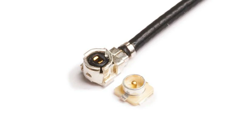
A close-up comparison of an IPEX micro coaxial cable plug and PCB socket used in compact wireless products with limited installation space.
One common problem during RF component sourcing is inconsistent naming.
A buyer searching for an ipex connector may also find descriptions such as:
- IPEX MHF connector
- MHF series connector
- U.FL connector
- U.FL compatible connector
This happens because miniature RF connector families often have similar appearances and overlapping application areas.
For example, two connectors may both use:
- Small snap-on structures
- Micro coaxial cables
- PCB mounting designs
But differences can exist in:
| Checking Item | Why It Matters |
| Connector series | Determines whether mating is possible |
| Height specification | Affects mechanical clearance |
| Cable diameter | Influences routing and loss |
| Contact structure | Affects RF stability |
| Assembly tolerance | Impacts production consistency |
A replacement decision should not be based only on pictures.
In practical projects, engineers usually confirm the original connector drawing or sample before changing suppliers. This avoids problems such as:
- Connector cannot fully mate
- Cable direction does not match PCB layout
- Antenna performance changes after replacement
- Assembly workers experience installation difficulty
This is especially important when moving from prototype production to larger quantities.
Match IPEX selection with the complete RF design
An IPEX connector does not work independently. The connector, cable, PCB layout, and antenna together form the RF transmission path.
A suitable selection normally starts from the complete application requirement.
Consider the operating frequency first
Although many IPEX connectors are used in wireless products, different applications may operate at different frequency bands.
Examples:
- WiFi 2.4 GHz
- WiFi 5 GHz
- Bluetooth
- GNSS L1 band
- Cellular communication bands
The connector and cable assembly need to maintain stable impedance through the complete signal path.
Important RF parameters include:
- 50 ohm impedance
- VSWR
- Return loss
- Insertion loss
A connector with a suitable mechanical size but poor RF matching may create unnecessary signal reflection.
Select the cable according to installation conditions
The cable connected to an IPEX connector is usually a miniature coaxial cable.
For applications requiring lower signal loss, designers often evaluate the cable together with the connector and compare different miniature coaxial cable solutions before finalizing the design.
Consider the mechanical environment during installation
IPEX connectors are small, and their mechanical limitations need attention during assembly.
Common problems include:
- Excessive cable pulling
- Repeated connector mating
- Sharp cable bending
- Incorrect assembly angle
During production, operators usually need to apply force directly above the connector instead of pressing from the cable side.
For products that require frequent maintenance, the number of mating cycles and connector protection should also be considered.
Why IPEX Connector Selection Is More Than Finding a Small Connector
In miniature wireless designs, the connector occupies only a small area on the product drawing, but it can influence the entire RF path.
A reliable IPEX solution requires matching:
- Connector series
- Cable specification
- Frequency requirement
- Antenna position
- Mechanical structure
Choosing the correct connector at the beginning of a project can reduce later changes during testing and mass production.
In the next section, we will continue with IPEX vs U.FL connector comparison, IPEX cable selection methods, and practical identification tables to help engineers avoid common replacement mistakes.
How Are IPEX and U.FL Connectors Related?
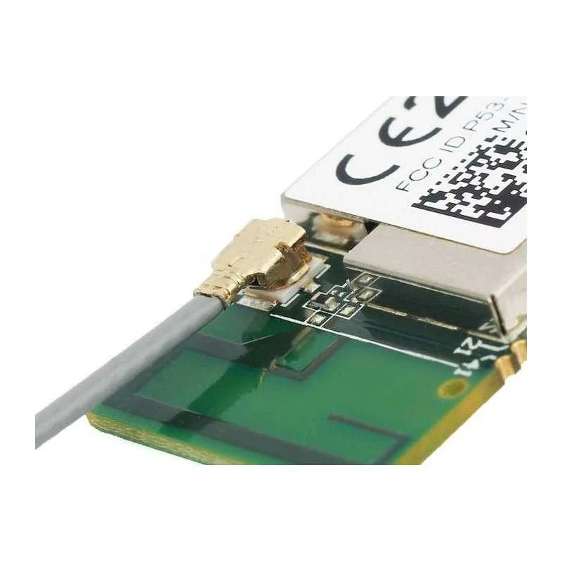
Close-up of an IPEX cable connection on a wireless module PCB, showing how miniature RF connectors route signals from the module to an internal or external antenna.
In miniature RF projects, one question appears again and again during component selection:
Can an IPEX connector be replaced by a U.FL connector?
The short answer is: sometimes, but not always.
The reason this question exists is simple. Both connectors are very small, both are used with micro coaxial cables, and both can be found on wireless modules.
A product photo may show two connectors that look almost identical. A purchasing team may even receive a quotation using a different name for what appears to be the same part.
However, RF connectors are not selected by appearance alone.
A few small differences can decide whether the assembly works correctly:
- Contact structure
- Mating height
- Connector series
- Cable routing direction
- Mechanical tolerance
In a wireless product, the connector is the transition point between the PCB RF circuit and the antenna cable. A mismatch here may not stop the device from turning on, but it can affect antenna efficiency, signal stability, and production consistency.
Why Do Engineers Compare IPEX and U.FL Connectors?
The comparison between IPEX connector and U.FL connector usually appears in compact wireless hardware.
Typical products include:
- WiFi modules
- Bluetooth boards
- Laptop wireless cards
- GPS receivers
- Industrial IoT terminals
The reason is related to the internal structure of these devices.
The antenna is often not placed directly beside the RF chip. Designers may need to move the antenna to another area of the product because of:
- Housing limitations
- Metal shielding
- Signal interference
- Industrial design requirements
A small coaxial cable solves this layout problem.
The signal path becomes:
RF chipset → PCB trace → IPEX/U.FL connector → micro coax cable → antenna
The connector itself takes very little space, but its connection quality affects the whole path.
For example, a wireless module installed inside a gateway may use a miniature connector because there is limited room around the PCB. The cable then runs toward an external antenna location.
This is where miniature RF connectors are valuable: they solve a mechanical problem without creating a large RF transition.
Why Cannot You Select a Replacement Only From the Connector Appearance?
One common situation during sourcing is finding a connector that looks similar and assuming it can replace the original model.
This approach often creates problems later.
A miniature RF connector needs to match the complete assembly.
Before replacement, check:
| Item to Confirm | Possible Problem If Ignored |
| Connector series | Plug and socket cannot mate |
| Mating height | Connector position does not match PCB |
| Cable diameter | Cable routing becomes difficult |
| Cable direction | Antenna installation changes |
| RF specification | Signal performance may change |
| Mechanical tolerance | Production yield decreases |
A connector may physically attach to the board but still fail in actual use.
Examples:
A cable exits in the wrong direction and cannot fit inside the enclosure.
A connector locks but has excessive movement after assembly.
A similar-looking part changes the antenna matching condition.
These problems are difficult to identify from product pictures alone.
In many development projects, the safest method is checking:
- Original part number
- Connector drawing
- Mating sample
- Cable assembly specification
before approving a replacement.
IPEX vs U.FL Identification Table
The following table can be used during the first stage of connector evaluation.
| Comparison Item | IPEX Connector | U.FL Connector |
| Connector Type | Miniature RF connector | Miniature RF connector |
| Main Application | Internal RF connection | Internal antenna connection |
| Mounting Method | Snap-on PCB connection | Snap-on PCB connection |
| Cable Compatibility | Micro coaxial cable | Micro coaxial cable |
| Typical Product Area | Wireless modules, embedded devices | Wireless cards, antenna modules |
| Replacement Check | Confirm exact series | Confirm mating specification |
| Main Risk | Similar-looking connector versions | Wrong mechanical matching |
This table is not a replacement for a drawing review. It is mainly used to quickly identify whether two connector options belong to the same application category.
How Should You Select an IPEX Cable for a Miniature RF System?
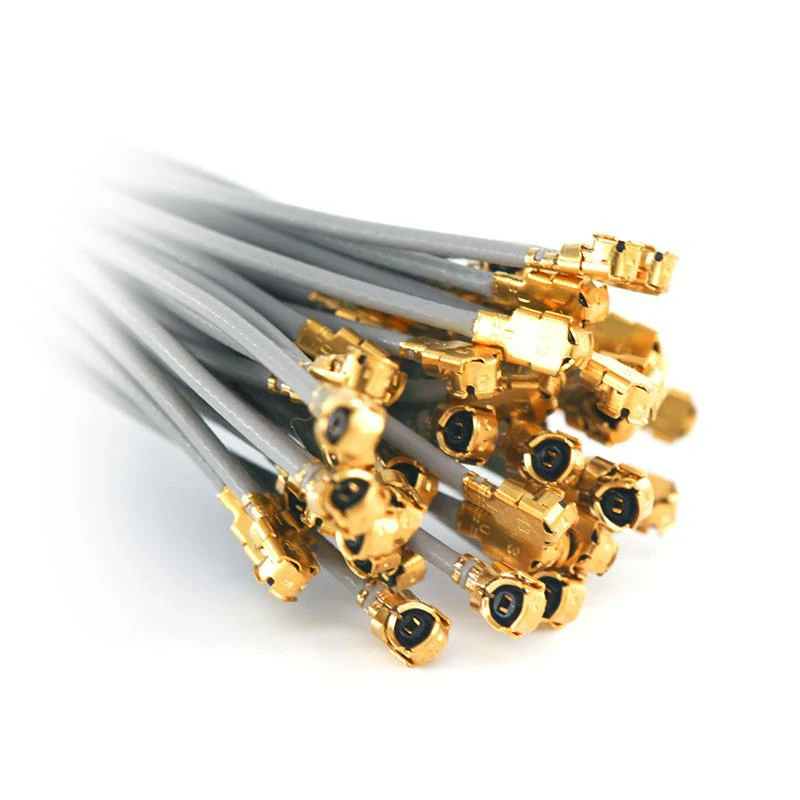
A bundle of micro coaxial cables terminated with miniature IPEX-style RF connectors for WiFi modules, Bluetooth equipment, GNSS receivers, and compact IoT devices.
After confirming the connector interface, the next issue is usually the cable.
An ipex cable is not just a connector with a wire attached. The cable becomes part of the RF transmission path.
In compact products, cable selection often involves a compromise between three things:
- Installation space
- Mechanical flexibility
- RF performance
A cable that works well in one device may not be suitable for another product with different internal structure.
How Does Cable Diameter Affect IPEX Applications?
Miniature RF cable assemblies usually use small coaxial cables.
However, a smaller diameter also means the cable construction has less space for shielding and conductor structure.
When cable length increases or frequency rises, designers usually pay more attention to:
- Attenuation
- Shielding performance
- Mechanical durability
The smallest cable is not always the best choice.
How Should You Balance Flexibility and RF Performance?
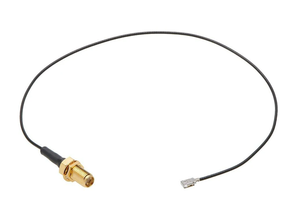
A miniature IPEX to SMA female bulkhead coaxial cable assembly commonly used in WiFi, Bluetooth, GNSS, IoT, and embedded wireless equipment.
In a prototype stage, flexibility is often the first concern.
A longer cable used in a communication device may need more attention to RF loss.
The final selection depends on the complete system rather than the connector alone.
IPEX Cable Selection Matrix
| Application Situation | Cable Selection Direction |
| Laptop wireless card | Flexible thin micro coax |
| Compact IoT equipment | Small diameter cable |
| Prototype RF testing | Easy replacement cable assembly |
| External antenna connection | IPEX to SMA cable |
| Higher frequency system | Lower loss miniature coax |
| Limited installation space | Small bend-radius cable |
This type of selection table is useful when preparing an RF cable assembly specification because it converts the product requirement into measurable cable requirements.
When Is an IPEX to SMA Cable Needed?
An IPEX connector is usually installed inside the device.
But during testing, debugging, or antenna evaluation, engineers often need to connect the internal RF port with external equipment.
This is where an IPEX to SMA cable becomes useful.
Connect Internal Wireless Modules With External RF Equipment
SMA connectors are common on:
- RF test instruments
- External antennas
- Development boards
IPEX connectors are common inside:
- Wireless modules
- Embedded systems
- Compact electronics
The conversion cable connects these two environments.
Typical applications include:
- Antenna tuning
- Prototype testing
- Signal measurement
- Wireless module evaluation
During development, this type of cable saves engineers from redesigning the PCB just to add a larger RF connector.
Why Should Cable Length Be Controlled?
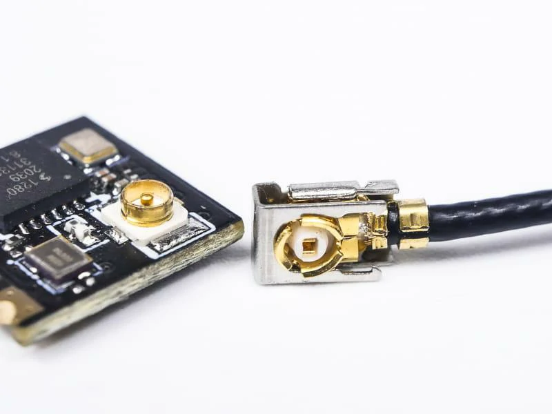
Detailed view of a miniature IPEX-style RF connector and PCB socket used for connecting wireless modules to internal antennas in compact electronic devices.
Every additional cable length changes the RF path.
Possible effects include:
- Additional insertion loss
- Phase variation
- Different measurement results
For simple prototype testing, a longer cable may be acceptable.
For accurate RF measurements, cable length usually needs to be controlled.
Before ordering an IPEX cable assembly, it is better to confirm:
- Required length
- Frequency range
- Connector type
- Test requirement
This avoids selecting a cable that fits mechanically but does not meet the RF requirement.
How Do MHF Series Connectors Fit Into IPEX Applications?
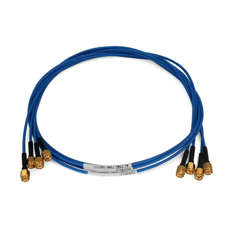
A miniature IPEX to SMA female bulkhead coaxial cable assembly commonly used in WiFi, Bluetooth, GNSS, IoT, and embedded wireless equipment.
When purchasing miniature RF cable assemblies, many buyers do not search only for “IPEX connector”.
They may also use terms such as:
- MHF connector
- IPEX MHF connector
- U.FL compatible connector
This often happens because different suppliers describe miniature RF products in different ways.
In a project discussion, one engineer may call it an IPEX connector, while another supplier may describe the same application using an MHF series name.
However, RF purchasing cannot rely only on naming.
A cable assembly that looks similar in a product image may still have differences in:
- Plug dimensions
- PCB connector height
- Cable type
- Mating force
- Frequency capability
Understand the Relationship Between IPEX and MHF Naming
The reason MHF appears frequently in IPEX discussions is that both are related to miniature RF connection solutions.
These connectors are designed for situations where traditional RF interfaces cannot fit.
For example:
A wireless module inside a smart device may only have a small area available near the antenna port.
A large threaded connector would occupy unnecessary space.
A miniature snap connector combined with a thin coaxial cable provides a more practical solution.
In actual projects, suppliers usually identify the product by:
- Original connector model
- Drawing number
- Matching socket specification
- Cable assembly requirement
rather than only the product title.
This is especially important when replacing an existing supplier.
A replacement connector may connect successfully during sample testing but create problems after entering production because the assembly tolerance is different.
Verify the Connector Series Before Ordering
A small RF connector contains several precision parts.
Before mass production, the following details normally need confirmation:
| Check Point | Why It Needs Confirmation |
| Connector series | Avoid incompatible mating |
| Cable diameter | Match internal routing space |
| Connector direction | Fit the product structure |
| Cable length | Control installation position |
| Frequency range | Match RF application |
| Test requirement | Confirm acceptance standard |
A typical mistake happens when a customer provides only a photo.
The supplier can identify the approximate connector type, but cannot always confirm:
- Exact series
- Mechanical height
- Internal contact structure
- Required cable specification
For customized IPEX cable assemblies, a drawing or sample is usually the most reliable reference.
How Do IPEX Connectors Support Wireless Applications?
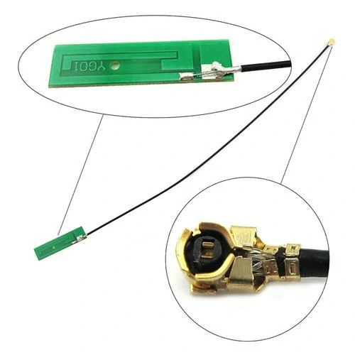
An internal PCB antenna assembly using an IPEX micro coaxial cable, with an enlarged view of the miniature RF connector termination
The reason miniature connectors remain popular is not only their small size.
The bigger advantage is design flexibility.
Modern wireless products often separate the RF module and antenna because the best antenna position is not always next to the main PCB.
An IPEX cable assembly provides this connection.
Apply IPEX Connectors in WiFi and Bluetooth Modules
WiFi and Bluetooth devices are common examples.
Inside these products, the antenna location affects:
- Wireless range
- Signal stability
- Product layout
A miniature cable gives designers more freedom.
For example:
A smart gateway may place the communication module in the center of the PCB, while the antenna needs to stay close to the plastic housing.
Instead of redesigning the whole PCB, an IPEX cable can route the RF signal to the antenna position.
This approach is widely used in:
- Wireless routers
- Smart home devices
- Industrial controllers
- Embedded communication products
Use IPEX Connectors in Laptops and Compact Devices
Thin products create another challenge: space.
Laptop wireless cards and embedded computers usually have strict limitations:
- Low internal height
- Limited cable routing space
- Small antenna area
In these products, cable assembly quality becomes important.
A connector that works well in a laboratory sample may still require careful evaluation before production.
Connect IPEX With GNSS and Antenna Modules
GNSS equipment often requires stable antenna connections.
A longer cable creates additional signal attenuation.
Therefore, when selecting an IPEX cable assembly, buyers usually need to provide:
- Required cable length
- Working frequency
- Installation environment
- Expected RF performance
A suitable cable specification helps avoid unnecessary changes during testing.
How Can You Maintain RF Performance With IPEX Connections?
A miniature connector is only one part of the RF system.
The actual signal path includes:
- PCB layout
- Connector
- Coaxial cable
- Antenna
Any part of this path can influence the final result.
Control Impedance in Miniature RF Paths
Most wireless RF systems are designed around 50 ohm impedance.
For an IPEX cable assembly, impedance consistency depends on:
- Connector design
- Cable structure
- Assembly process
A poor connection may cause:
- Higher reflection
- Increased VSWR
- Reduced transmission efficiency
This is why RF cable suppliers usually test finished assemblies instead of checking only the raw components.
Check RF Parameters After Cable Assembly
For customized IPEX cable assemblies, common inspection items include:
- Continuity
- VSWR
- Return Loss
- Insertion Loss
Different customers may have different acceptance standards.
For example:
A prototype customer may only require basic electrical confirmation.
An industrial customer may require complete RF test data before shipment.
The inspection method should match the final application.
Protect Miniature Connectors During Installation
The small size of IPEX connectors also means they need careful handling.
During assembly:
Do:
- Press vertically when mating
- Keep the cable close to the designed bending area
- Avoid unnecessary reconnection
Avoid:
- Pulling the cable directly
- Bending the connector area repeatedly
- Applying side force during installation
Many connector failures are not caused by the connector itself, but by incorrect assembly methods.
How Can You Verify IPEX Cable Assembly Quality Before Shipment?
For customized RF cable production, shipment inspection is usually divided into two parts:
Mechanical inspection and electrical inspection.
A cable may look perfect but still require RF testing.
Inspect Mechanical Connection Quality
Before shipment, production teams normally check:
- Connector appearance
- Cable length
- Connector orientation
- Assembly position
- Cable damage
For customized products, the inspection also compares the finished product with the approved sample or drawing.
How Should Buyers Specify IPEX Connectors for Custom Production?
A common quotation problem is incomplete information.
For example:
“Please quote IPEX cable.”
This description is usually not enough.
A miniature RF cable assembly requires more details.
Define Connector Information Before Quotation
The basic information should include:
- Connector model
- Cable specification
- Cable length
- Connector direction
- Drawing or sample
A 100 mm cable and a 500 mm cable may use the same connector but have completely different production requirements.
Add RF Requirements to the Specification
For engineering projects, buyers should also provide:
- Frequency range
- Impedance
- VSWR requirement
- Insertion loss requirement
- Operating temperature
This helps suppliers select the correct cable and testing method.
How Are Miniature RF Connectors Evolving in New Wireless Devices?
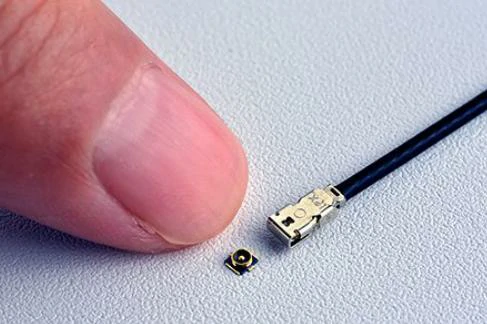
A scale comparison demonstrating the compact dimensions of an IPEX miniature RF connector used in laptops, wireless cards, IoT modules, and embedded devices.
Wireless products continue moving toward smaller designs.
At the same time, users expect:
- Faster communication
- Smaller equipment
- Better wireless stability
This creates higher requirements for miniature RF solutions.
Balance Miniaturization With Reliability
Smaller does not always mean better.
A successful RF design still needs:
- Stable connection
- Suitable cable performance
- Reliable assembly
- Consistent production quality
The correct connector is the one that matches the entire system.
Reduce Unnecessary Conversions in Compact RF Systems
Every additional adapter creates another RF transition.
For compact products, reducing unnecessary connections can simplify:
- Assembly
- Testing
- Maintenance
A properly selected IPEX cable assembly can provide a direct connection between the RF module and antenna.
FAQ
Are IPEX and U.FL connectors interchangeable?
Not always. They belong to similar miniature RF applications, but the exact connector series and mating specification need to be confirmed.
Why are IPEX connectors used in wireless products?
Because they provide a compact RF connection for PCB modules and antennas where installation space is limited.
Can IPEX connect directly to SMA equipment?
Usually an IPEX-to-SMA cable assembly is required for connection with external RF equipment.
What cable is normally used with IPEX connectors?
Micro coaxial cables such as 1.13 mm and similar miniature coax cables are common choices.
