
A connector takes very little space on an RF board, but a wrong connector choice can affect the entire design.
For compact wireless products, the antenna connection is often placed in a very limited area. GPS trackers, IoT terminals, and communication modules usually cannot reserve the same installation space as traditional RF equipment. A large threaded connector may provide strong mechanical retention, but it may not fit the mechanical structure of the product.
The MMCX connector was created for this type of compact RF application.
The cable diameter, operating frequency, impedance, installation environment, and required mating performance all influence the final choice.
A connector that works well on a laboratory bench may not be the right choice for a production device.
How Should You Choose an MMCX Connector for Miniature RF Devices?
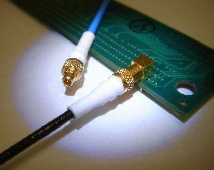
MMCX right-angle PCB connector and miniature coaxial cable used in a compact circuit board application where limited enclosure height and cable-routing space must be considered.
Explain mmcx connector from a compact RF design perspective
The mmcx connector belongs to the micro-miniature coaxial connector family.
Its main purpose is to provide a compact RF interface while maintaining the basic structure required for coaxial signal transmission.
Inside an MMCX connection, the RF signal travels through the center contact, while the outer conductor provides shielding and the return path.
This difference changes how the connector is used.
For example, inside a wireless module, the installer may need to connect an antenna cable after the PCB has already been assembled. A snap-on interface allows faster installation and requires less surrounding clearance.
Common MMCX applications include:
- GNSS receiver modules
- GPS tracking devices
- Wireless communication boards
- IoT sensor products
- Compact RF equipment
In a small positioning device, the RF cable may need to pass around the battery, enclosure wall, or other components. The small size of MMCX helps designers keep the internal layout more flexible.
Before finalizing a connector design, many engineers compare different RF connector structures through a complete RF connector guide to understand mechanical and electrical differences.
Match MMCX selection with space and electrical requirements
A miniature connector still needs to satisfy the electrical requirements of the RF system.
A common mistake in compact product development is choosing a connector based only on the external dimensions.
The actual RF connection depends on several combined factors.
| Parameter | Design Consideration |
| Connector size | Available PCB and housing space |
| Frequency range | Operating frequency of the RF system |
| Impedance | Usually 50Ω RF matching |
| Cable type | RG178, RG316, micro coaxial cable |
| Cable length | Signal loss and routing distance |
| Environment | Vibration, temperature, installation condition |
Take a GPS module as an example.
The connector may only carry a few millimeters of RF path on the PCB, but the attached cable may run several centimeters to the antenna position. At this point, cable loss and bending performance become as important as the connector itself.
For internal connections, flexible miniature coaxial cable is often preferred.
For external antenna ports, mechanical protection and connection reliability may become more important.
The final solution is normally a combination of connector, cable, and assembly process.
Understand where MMCX fits among miniature RF connectors
MMCX is often compared with MCX because both use snap-on coupling.
The difference is mainly related to size and mechanical requirements.
There is no universal “better” connector. The correct choice depends on the product structure and operating conditions.
How Do MMCX Male and Female Connectors Work Together?
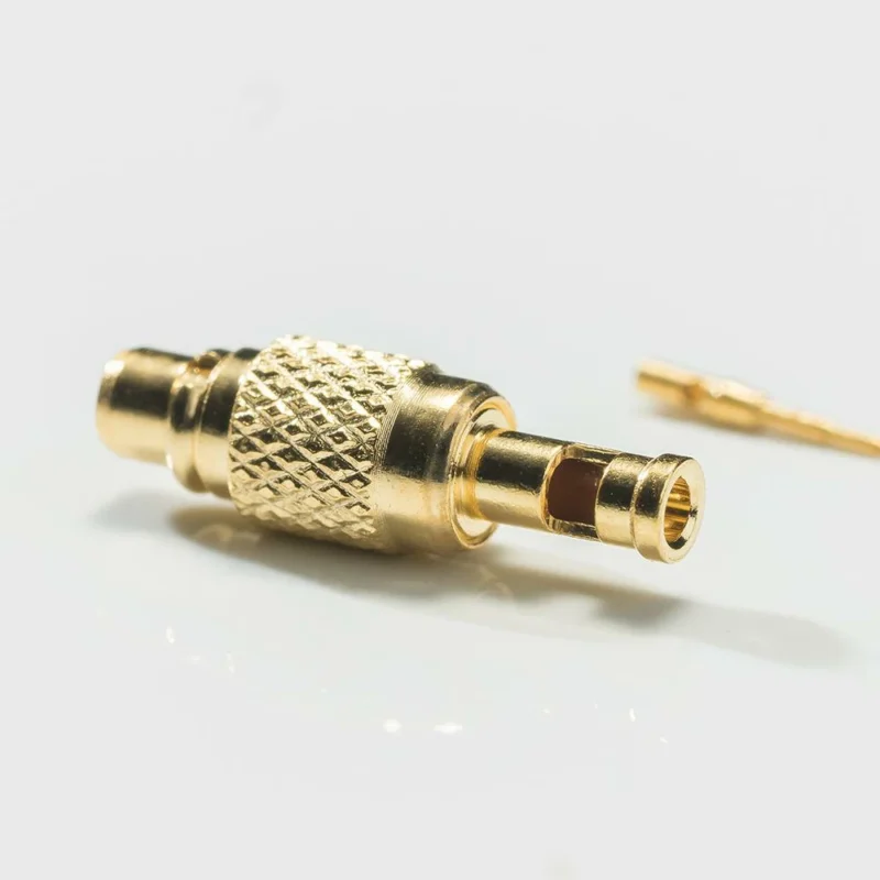
Identify the structure of an MMCX male connector
The MMCX male connector is normally attached to the coaxial cable.
Its main parts include:
- Center pin
- Cable termination section
- Outer metal body
- Snap connection structure
During installation, the male connector is pressed into the female socket.
Compared with threaded RF connectors, there is no tightening process. This makes MMCX convenient for applications where assembly space is restricted.
Typical uses include:
- Antenna extension cables
- Internal module connections
- Custom RF cable assemblies
Cable matching is an important part of MMCX design.
A connector designed for a small diameter cable cannot simply be installed on another cable type without considering the termination structure.
For example, RG178 and RG316 cables have different dimensions and electrical characteristics. The connector selection should match the actual cable specification.
MMCX Male vs Female Selection Table
| Field | MMCX Male | MMCX Female |
| Contact | Pin | Socket |
| Typical Location | Cable side | PCB/device side |
| Connection Method | Plug | Receptacle |
| Common Use | Antenna cable | RF module |
| Main Risk | Wrong mating | Port mismatch |
Verify MMCX interface matching before assembly
Before starting production, several details should be confirmed:
- MMCX male or female
- Straight or right-angle design
- Cable model
- Cable length
- Operating frequency
- Impedance requirement
- Required RF test items
For custom RF products, incomplete specifications are one of the most common reasons for redesign.
A complete requirement usually includes both mechanical information and electrical requirements.
For example:
- Connector model
- Cable specification
- Assembly length
- Frequency range
- VSWR requirement
- Test method
This information allows the cable assembly to be produced according to the actual application instead of only matching the connector appearance.
Why Does MMCX Cable Selection Matter in Compact RF Systems?
A lot of RF problems do not start from the connector itself.
During product testing, engineers sometimes find that the MMCX interface is working correctly, but the complete antenna path still shows unexpected loss or unstable signal performance.
The reason is usually related to the cable.
This creates a common design trade-off:
A thinner cable is easier to install, but it may have higher loss.
A thicker cable may provide better electrical performance, but it can make internal assembly difficult.
That is why choosing an MMCX cable requires looking at the whole application instead of only checking the connector interface.
Choose MMCX cable based on routing limitations
Small wireless products leave very little room for cable routing.
A GPS module installed inside a vehicle tracker is a typical example. The antenna may be placed several centimeters away from the main PCB, and the cable needs to travel around batteries, shielding covers, or mounting structures.
In this situation, cable flexibility becomes important.
Common points to confirm include:
Cable diameter
A smaller cable is easier to install in compact products.
It is commonly used for:
- Wearable devices
- Miniature IoT equipment
- Internal antenna connections
However, reducing cable size also changes the conductor and shielding structure. This can affect attenuation and mechanical durability.
Bending condition
A cable that looks suitable on a drawing may behave differently during actual assembly.
Repeated bending near the MMCX connector can create stress on the termination area.
For products that experience movement or vibration, the cable construction needs to be considered together with the connector design.
Cable length
RF loss increases as cable length increases.
A 50 mm internal cable and a 1 m antenna extension cable have completely different requirements.
Short internal connections usually focus more on:
- Installation space
- Flexibility
- Assembly convenience
Longer connections require more attention to:
- Insertion loss
- Shielding
- Frequency characteristics
Match MMCX connectors with miniature coaxial cables
MMCX connectors are usually paired with small coaxial cables.
Common choices include:
- RG178
- RG316
- Micro coaxial cable
Each option has its own application preference.
| Cable Type | Typical Characteristics | Suitable Application |
| RG178 | Small diameter, lightweight | Space-limited internal connection |
| RG316 | More durable structure | General RF cable assembly |
| Micro coaxial cable | Extremely compact | Miniature electronic products |
RG178 is often selected when the available installation space is very limited.
RG316 is commonly considered when the product needs a balance between flexibility and mechanical reliability.
Micro coaxial cables are used in some highly integrated devices where traditional coaxial cables cannot fit.
There is no single cable that works for every MMCX application.
The final choice depends on the product structure, frequency requirement, and expected operating environment.
When Should You Use an MMCX Adapter?
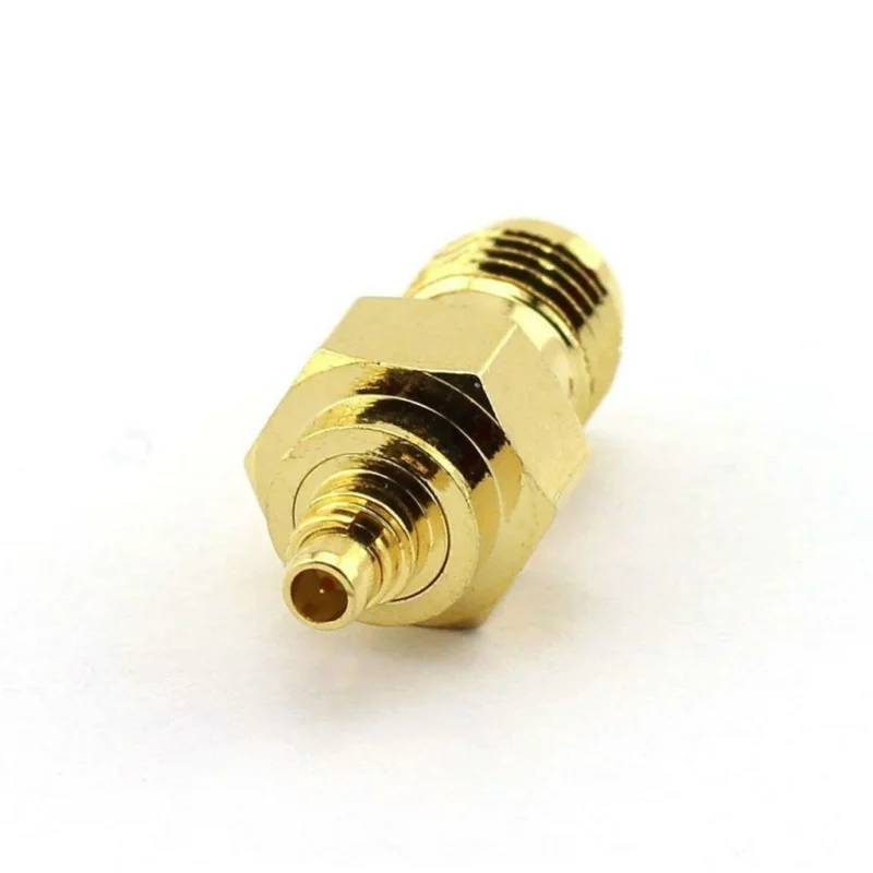
During prototype development, different RF devices often use different connector interfaces.
A wireless module may provide an MMCX port, while the test equipment on the bench uses SMA.
The two connectors cannot mate directly.
This is where an MMCX adapter becomes useful.
Convert MMCX interfaces in mixed RF systems
A common development situation:
A customer receives a wireless module with an MMCX female connector but already has SMA test cables available.
Replacing the whole cable system may not be practical.
An MMCX to SMA adapter creates a temporary connection between the two interfaces.
This approach is often used for:
- Prototype testing
- Antenna evaluation
- RF debugging
- Laboratory measurement
However, production products usually avoid unnecessary adapter combinations.
Every additional connector creates another mechanical joint in the RF path.
Verify impedance and frequency before adding adapters
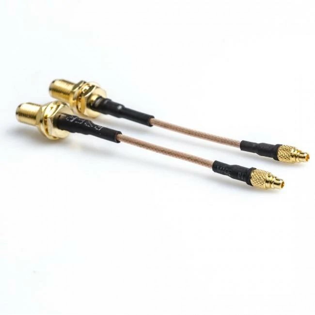
MMCX to SMA female RF cable assemblies using flexible miniature coaxial cable, suitable for GPS modules, embedded antennas, wireless communication boards, and compact RF equipment.
An adapter is a small component, but electrically it is still part of the transmission line.
Before selecting an MMCX adapter, confirm:
- 50Ω impedance
- Required frequency range
- Male/female interface
- Straight or angled structure
- Installation requirements
An incorrect adapter may introduce:
- Additional insertion loss
- Poor return loss
- Higher VSWR
This becomes more noticeable at higher frequencies.
For RF systems above several GHz, connector matching and assembly quality become increasingly important.
Reduce unnecessary adapter transitions
Adapters are useful during testing.
They are less attractive as a permanent production solution.
A chain like:
Module → MMCX adapter → SMA adapter → Cable
creates more interfaces than:
Module → Custom MMCX cable assembly
A shorter signal path usually makes production control easier.
For volume products, a dedicated cable assembly can reduce:
- Assembly steps
- Connection points
- Potential failure locations
How Does MMCX Compare With MCX in RF Applications?
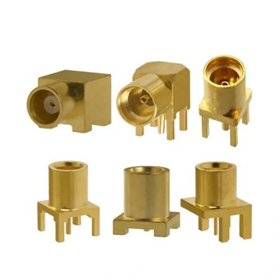
A selection of straight and right-angle MMCX PCB mount connectors designed for compact wireless modules, GPS receivers, IoT devices, and embedded RF circuit boards.
MMCX and MCX are sometimes confused because both use snap-on coupling.
The difference is mainly the mechanical size.
MMCX was designed for applications where installation space is limited.
MCX keeps a larger structure, providing more mechanical margin.
Compare MMCX and MCX mechanical designs
MMCX vs MCX Comparison Table
| Field | MMCX | MCX |
| Size | Smaller | Larger |
| Connection | Snap-on | Snap-on |
| Mechanical Strength | Medium | Higher |
| Space Requirement | Lower | Higher |
| Typical Use | Mini PCB/modules | GPS/modules |
Choose MMCX when size is the priority
MMCX is often found in products where the connector location is difficult to access after assembly.
Examples:
- Compact wireless modules
- Embedded antennas
- Portable electronic devices
The smaller footprint gives designers more freedom when arranging the PCB and enclosure.
For highly integrated products, saving several millimeters can affect the entire mechanical design.
Choose MCX when handling strength matters more
MCX provides a larger interface.
It may be a better fit when:
- The connector is exposed externally
- The cable may be moved frequently
- Mechanical loading is higher
A connector used inside a sealed IoT device and a connector used on an external test port face completely different conditions.
That difference should guide the selection.
How Does MMCX Compare With SMA for RF Connections?
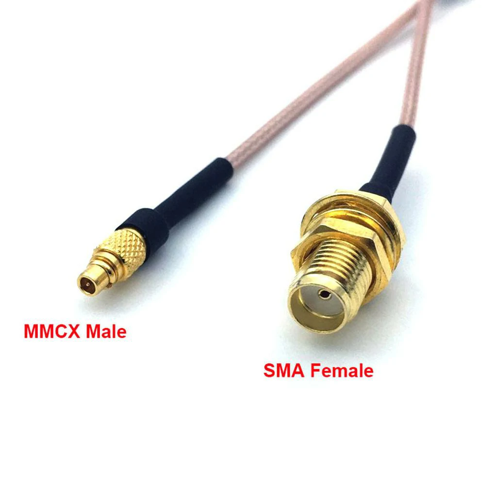
Flexible MMCX male to SMA female coaxial cable assembly designed for RF modules, GNSS receivers, GPS trackers, wireless boards, and antenna extension applications.
In RF projects, SMA is often the first connector that comes to mind.
It is familiar, easy to test, and widely supported by RF instruments. During early development, many engineers use SMA connectors simply because test equipment, adapters, and cables are easy to find.
The situation changes when the product becomes smaller.
A prototype board may have enough space for SMA. After moving into a finished enclosure, the same connector can become difficult to install because of height limitations, PCB layout restrictions, or cable routing problems.
This is one reason MMCX connectors are used in compact RF products.
The difference between MMCX and SMA is mainly related to design purpose.
SMA was developed around secure threaded connection.
MMCX was designed for applications where space is limited and quick connection is needed.
Compare MMCX and SMA interfaces
| Item | MMCX | SMA |
| Interface size | Compact | Larger |
| Locking method | Snap connection | Threaded connection |
| Installation space | Small electronic devices | General RF equipment |
| Mechanical fixing | Suitable for internal applications | Suitable for repeated connection |
| Typical use | GPS modules, wireless boards | Test cables, antennas, RF equipment |
Select based on the working environment
A common mistake is choosing a connector only from the electrical specification.
Two connectors may both support a 50Ω RF system, but the mechanical environment can be completely different.
For example:
A GNSS module inside a tracking device may never be touched after assembly.
The priority is usually:
- Small footprint
- Simple installation
- Flexible cable routing
An RF test cable used in a laboratory may be connected hundreds of times.
The priority changes to:
- Strong mechanical locking
- Stable repeated connection
- Easy maintenance
In these two situations, MMCX and SMA solve different problems.
Where Are MMCX Connectors Used in Modern Wireless Devices?
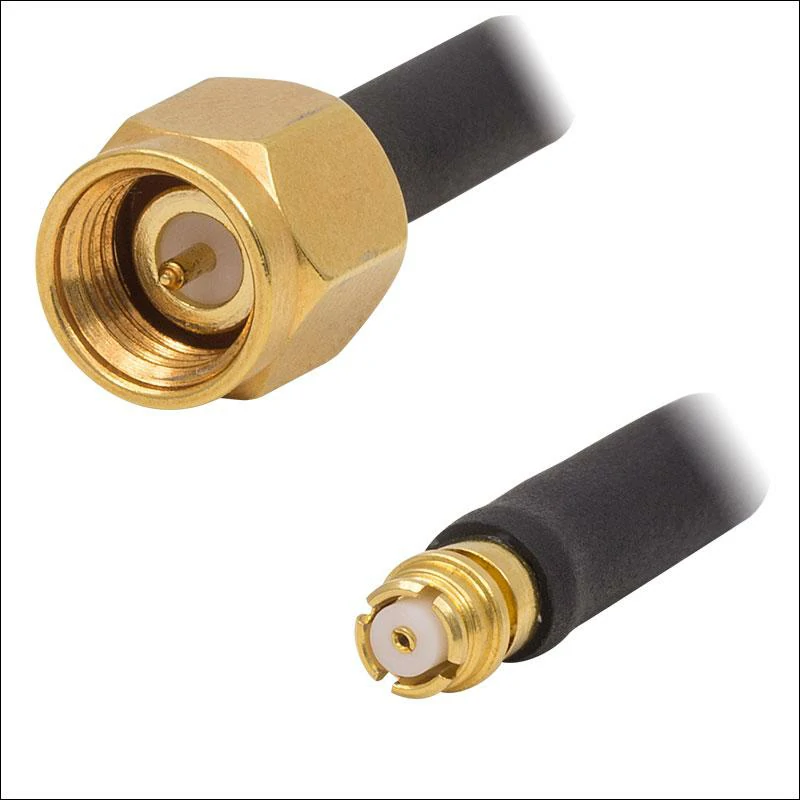
SMA male to MMCX male coaxial cable assembly for connecting RF test equipment, external antennas, communication modules, and miniature wireless devices.
The use of MMCX is closely related to product miniaturization.
Many wireless products now place the RF module, power supply, antenna, and control circuit inside very limited spaces.
The connector cannot be considered separately from the mechanical design.
A few millimeters of difference can affect:
- PCB arrangement
- Housing design
- Antenna position
- Cable routing method
Apply MMCX connectors in GPS and GNSS systems
GPS and GNSS modules are typical examples.
The RF module is usually installed on the main board, while the antenna may be positioned somewhere else.
The cable between them needs to pass through the available internal space.
A practical MMCX cable design needs to consider:
- Cable diameter
- Cable length
- Minimum bending radius
- Frequency requirement
A short cable inside a navigation module and a longer antenna cable outside the enclosure have different requirements.
For short internal connections, flexibility may be more important.
For longer connections, signal loss becomes a bigger concern.
Many GPS applications use MMCX because the connector size allows more freedom in mechanical layout.
Use MMCX connectors in IoT and embedded electronics
IoT products usually have strict size limitations.
A small wireless sensor may need to contain:
- Battery
- Communication module
- Antenna
- Sensor components
- Control circuit
Space is limited, and every component affects the final structure.
MMCX connectors are often used on these products because they can connect the antenna system without taking up much board area.
Common applications include:
- Industrial sensors
- Wireless monitoring devices
- Smart terminals
- Embedded communication products
The cable direction is also important.
A right-angle MMCX assembly may work better than a straight version when the enclosure height is restricted.
Support compact antenna designs with MMCX interfaces
The antenna location is not always determined only by the PCB.
In many products, the antenna needs to be placed in an area with better signal conditions.
This creates a design requirement:
The RF module and antenna cannot always sit next to each other.
An MMCX cable connection provides more flexibility between these two positions.
The designer can adjust the antenna location without changing the complete PCB structure.
How Can You Maintain RF Performance With MMCX Connections?
Small connectors still need proper RF control.
A cable assembly may pass mechanical inspection but fail during RF measurement.
Typical reasons include:
- Incorrect cable termination
- Poor contact
- Impedance variation
- Assembly inconsistency
The connector is only one part of the complete RF path.
Control impedance in miniature RF paths
Most MMCX applications use 50Ω systems.
Maintaining impedance consistency requires attention to the entire connection.
Possible influencing factors include:
- Connector design
- Cable structure
- PCB grounding
- Assembly process
At lower frequencies, small differences may not be obvious.
As frequency increases, these details become easier to detect during testing.
Protect MMCX interfaces during repeated mating
MMCX uses a compact snap-on structure.
This makes installation convenient, but the connector should still be used within its intended environment.
Before selecting MMCX for an external connection, consider:
- Connection frequency
- Cable movement
- Installation accessibility
- Mechanical load
A connector hidden inside equipment and a connector exposed to daily operation should not follow the same selection standard.
How Can You Verify MMCX Connector Quality Before Production?
Before production quantities are released, MMCX products normally require both mechanical confirmation and RF verification.
A sample that looks correct does not always represent the final batch performance.
Test MMCX cable assemblies before shipment
Electrical tests normally depend on customer requirements.
Common items include:
- Continuity test
- VSWR test
- Return Loss test
- Insertion Loss test
For RF products, the test record is also important.
It helps customers confirm that the delivered cable assembly matches the approved sample.
How Should Buyers Specify MMCX Connectors for Custom Production?
For custom RF orders, the connector name is only the starting point.
A complete requirement usually needs more information.
For example:
“MMCX cable, 100 pcs”
does not define the final product.
Production still needs to know:
- Which MMCX interface?
- Which cable?
- How long?
- What frequency?
- What test standard?
Clear specifications reduce unnecessary modification after production.
Add RF requirements before manufacturing
Technical requirements should include:
- Frequency range
- Impedance
- VSWR
- Insertion loss
- Temperature requirement
- Test method
For customers using MMCX assemblies in larger projects, providing drawings or sample references can make production communication much easier.
Custom MMCX Cable Specification Template
| Field | Information Required |
| Connector Type | MMCX model |
| Gender | Male / Female |
| Cable Model | RG178 / RG316 / Micro coax |
| Cable Length | Finished length |
| Frequency Range | Working frequency |
| Impedance | 50Ω |
| Mounting Style | Straight / Right angle |
| Temperature Range | Operating condition |
| RF Test Requirement | VSWR / Loss |
| Drawing Requirement | Mechanical drawing |
How Do Miniature RF Trends Increase MMCX Usage?
Smaller wireless products continue to change RF connector selection.
The challenge is no longer only transmitting signals.
The connector also needs to fit:
- Smaller housings
- More compact PCBs
- More complicated internal structures
MMCX is one solution for this direction.
Connect MMCX with IoT and wearable electronics growth
Many portable devices require wireless communication while keeping the product size small.
The RF interface needs to occupy less space without creating additional assembly difficulty.
This makes miniature connectors increasingly common in:
- IoT devices
- Portable electronics
- Wireless modules
Balance miniaturization and RF reliability
Reducing size does not remove the need for quality control.
A reliable MMCX connection still depends on:
- Correct connector selection
- Suitable cable matching
- Proper assembly
- Electrical verification
Miniaturization and RF performance need to be considered together.
Reduce unnecessary conversions in miniature RF designs
Adapters are useful during testing and development.
For production products, fewer connection points usually make the system easier to control.
A customized MMCX cable assembly can combine:
- Required connector interfaces
- Cable length
- Electrical requirements
into one tested component.
FQA
Why are MMCX connectors used in compact RF products?
They provide a small RF interface suitable for limited PCB space and embedded antenna applications.
Can MMCX connect directly to SMA?
No. The two interfaces use different mechanical structures and require an adapter or cable assembly.
