
How Should You Select an MCX Connector for Compact RF Designs?
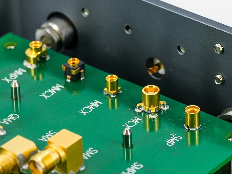
Close-up of multiple miniature RF connectors mounted on a printed circuit board, including MCX, MMCX, and SMP-style interfaces. The image illustrates differences in connector size, PCB footprint, mounting structure, and installation requirements.
When a new RF product enters the mechanical design stage, the connector is usually not the first component engineers think about.
The antenna, RF IC, shielding structure, and enclosure normally receive more attention. The connector becomes important later, especially when the available space around the RF interface becomes limited.
This is one reason the MCX connector appears frequently in compact electronic products.
MCX is a miniature coaxial connector designed for applications where a full-size RF connector would occupy too much space. Instead of a threaded locking structure, MCX uses a snap coupling interface. This makes the connection process faster and allows the connector height and footprint to remain relatively small.
In practical designs, MCX is often found near the antenna interface of GPS receivers, wireless modules, and embedded communication products.
The connector choice is rarely only about size.
A connector that fits the mechanical drawing may still create problems later if the cable routing, mating direction, or RF requirements are not considered at the beginning.
Why does connector selection become difficult in miniature RF systems?
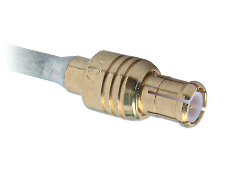
Close-up of a straight MCX crimp connector installed on a small-diameter coaxial cable. Proper cable termination, shielding contact, and center conductor alignment are important for maintaining reliable mechanical and RF performance.
Space reduction changes many design decisions.
A standard RF connector may perform well electrically, but its body size can interfere with:
- PCB placement
- enclosure height
- cable bending radius
- assembly operation
For example, a GPS tracking device may require the antenna cable to exit from a narrow corner of the housing. The connector needs to fit the available angle, but the cable also needs enough flexibility to avoid excessive stress.
This is where miniature interfaces such as MCX become useful.
However, smaller does not always mean easier.
The smaller contact structure requires better control during assembly.
A flexible coaxial cable such as RG178 or RG316 may be selected depending on the bending requirement, attenuation target, and available installation space.
How is an MCX male connector used in RF assemblies?
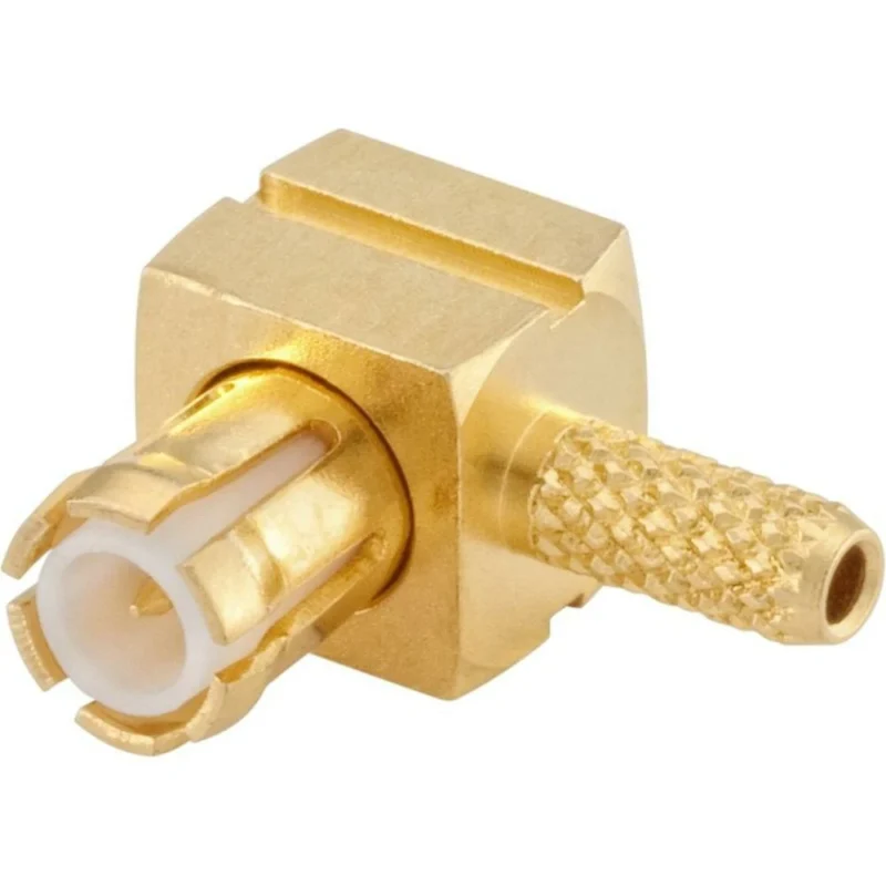
The MCX male connector is normally located at the cable end.
Its center contact connects with the signal conductor inside the coaxial cable. The outer shell maintains the shielding path required for coaxial transmission.
During assembly, the connector termination process has a direct influence on reliability.
For miniature RF cables, problems often appear during production rather than during initial design review.
How is an MCX female connector integrated into equipment?
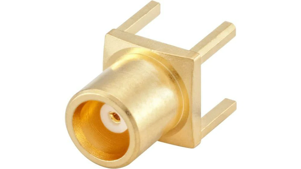
Gold-plated MCX female PCB mount connector featuring a socket contact and multiple mounting legs. It is designed for GPS boards, wireless communication modules, test boards, and other compact RF equipment.
The MCX female connector is commonly installed on the equipment side.
Typical locations include:
- RF modules
- GPS receiver boards
- wireless communication devices
- test boards
Unlike the cable-side connector, the female interface needs to work with the PCB layout.
The surrounding grounding area, mounting strength, and connector position can influence assembly quality.
In compact designs, a few millimeters of placement difference may affect whether the cable can be installed smoothly inside the final enclosure.
MCX Male vs Female Selection Table
| Item | MCX Male | MCX Female |
| Installation position | Cable side | Equipment / PCB side |
| Contact form | Pin contact | Socket contact |
| Main function | Connect cable assembly | Receive external connection |
| Common application | Antenna cable | RF module interface |
| Main risk | Cable termination issue | Interface mismatch |
How Does MCX Cable Selection Affect RF System Design?
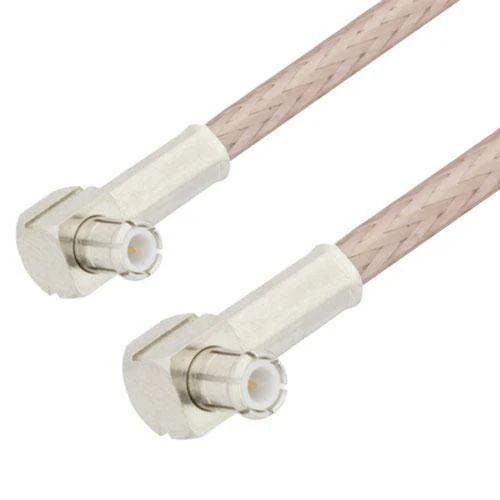
Miniature coaxial cable assembly terminated with right angle MCX connectors at both ends. The low-profile connector orientation helps reduce cable stress and simplifies routing inside GPS, IoT, automotive, and communication devices.
The connector is usually the first thing people notice in an RF interface, but the cable behind it often decides whether the assembly works well in the final product.
During prototype development, an MCX cable assembly may look simple:
connector → coaxial cable → connector
After moving into a real enclosure, more factors appear.
The cable may need to pass around a battery, avoid a shielding cover, or bend within a very limited area. A cable that performs well on a test bench may not be suitable for the production version.
This happens because RF design is not only about electrical specifications. The physical condition of the cable also becomes part of the signal path.
For miniature RF systems, the MCX connector is commonly paired with small coaxial cables such as RG178, RG316, or other micro coax options. The final selection depends on where the cable will be installed and how the product will be used.
Why does the cable become a limiting factor in compact devices?
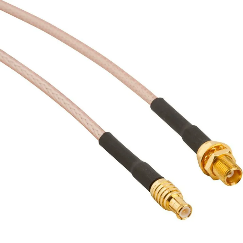
Reducing product size usually creates pressure on the RF cable.
A smaller enclosure means:
- less routing space
- tighter bending area
- shorter distance between components
- more difficult assembly access
A designer may choose a smaller cable because it fits better mechanically, but the thinner structure can also change attenuation, shielding effectiveness, and durability.
On the other hand, selecting a larger cable may improve mechanical strength but create problems during installation.
This is the trade-off often seen in GPS receivers, IoT devices, and vehicle communication products.
For example, an antenna cable inside a stationary device may use a flexible miniature coaxial cable with a small bending radius. A cable exposed to repeated movement may require a different construction even when both products use the same MCX interface.
The connector does not determine the complete RF performance. The cable and termination process need to be evaluated together.
Which cable specifications should be checked for MCX assemblies?
A cable drawing should provide more than the cable length.
For production evaluation, several details usually need confirmation:
| Item | Engineering Consideration |
| Cable diameter | Determines routing space and connector compatibility |
| Cable length | Influences signal loss and installation method |
| Shielding structure | Affects interference protection |
| Bend radius | Determines mechanical reliability |
| Conductor structure | Influences electrical consistency |
| Temperature rating | Matches product environment |
The same MCX connector can be used in different applications, but the cable selection may change completely.
A short cable inside a communication module and a one-meter antenna cable are not evaluated by the same criteria.
In high-frequency applications, even small differences in cable construction can appear during RF testing.
MCX Cable Selection Matrix
| Application Situation | Suitable Cable Direction | Main Concern |
| Compact PCB connection | Small diameter coaxial cable | Space limitation |
| Internal antenna connection | Flexible miniature coax | Routing and bending |
| Longer RF transmission path | Low loss coaxial cable | Attenuation control |
| Vibration environment | Strong mechanical structure cable | Connection reliability |
| Prototype testing | Flexible cable assembly | Easy modification |
How does cable installation affect MCX connection reliability?
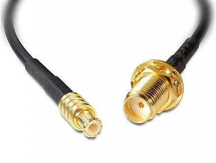
MCX-to-SMA female coaxial cable assembly designed for antenna extension and RF interface conversion. Commonly used in GPS receivers, wireless communication equipment, RF modules, routers, telemetry devices, and compact electronic systems.
Many RF problems are not caused by the connector itself.
They appear after the assembly is installed into the final product.
A cable that is forced into position can transfer mechanical stress directly to the connector interface.
Common situations include:
- cable bent immediately after the connector exit
- connector pulled during enclosure assembly
- insufficient clearance around the mating area
- repeated movement after installation
For MCX assemblies, the connection point is compact, so cable routing should be considered during mechanical design rather than after the PCB layout is finished.
A small change in cable direction can sometimes improve both assembly efficiency and product reliability.
What should be checked before selecting an MCX adapter?
Mechanical compatibility is only one part of adapter selection.
The important points include:
| Check Item | Reason |
| Impedance | Maintain RF matching |
| Frequency range | Avoid unsuitable operation range |
| Gender | Confirm correct mating direction |
| Connector structure | Prevent mechanical mismatch |
| Installation space | Ensure the adapter fits the enclosure |
A low-cost adapter may physically connect two interfaces but still create unexpected RF results if the electrical design is not suitable.
For measurement applications, adapter quality can also influence test repeatability.
Why should unnecessary adapters be avoided in production products?
Adapters are useful during development, but they are not always the best long-term solution.
Every additional connector interface adds:
- another mechanical tolerance
- another contact surface
- another possible source of loss
A prototype setup may contain several adapters because flexibility is more important than size.
A production product usually follows a different principle.
If the final design can use a direct MCX cable assembly instead of multiple conversions, the RF path becomes simpler and the assembly process becomes easier to control.
MCX Connector Selection in Real RF Projects: Size, Testing, and Production Considerations
How Does MCX Compare With MMCX During Real Product Design?
MCX and MMCX are often compared when engineers work on compact wireless products.
The two connectors solve a similar problem: providing an RF connection when PCB space is limited. However, the final selection is usually decided by more than the connector diameter.
During early prototype design, MMCX may appear attractive because it occupies less space. After moving into production, the situation can change.
A smaller connector also means:
- tighter assembly tolerance
- less room for handling
- more attention during cable installation
MCX takes a slightly different approach. It still keeps a compact structure, but the interface is easier to handle during assembly.
This difference becomes important when hundreds or thousands of units need to be assembled consistently.
A prototype built by an engineer and a production line operated by multiple workers are two different environments. The connector that works on a sample board may not always be the easiest choice for mass production.
MCX vs MMCX Comparison Table
| Item | MCX | MMCX |
| Physical size | Compact | More miniature |
| Connection method | Snap coupling | Snap coupling |
| Assembly handling | Easier | Requires more precision |
| Typical usage | GPS modules, communication equipment | Space-limited PCB applications |
| Cable assembly difficulty | Moderate | Higher tolerance requirement |
| Design priority | Balance between size and usability | Maximum space saving |
Why do some designers still choose MCX instead of smaller connectors?
In many projects, the smallest connector is not automatically the best solution.
A vehicle communication module is a good example.
The internal space may be limited, but the product also needs to handle:
- vibration
- repeated assembly
- cable movement
- temperature changes
A connector that is slightly larger may provide a more practical production solution.
MCX is often selected in these situations because it provides enough size reduction without making assembly unnecessarily difficult.
The same consideration applies to GPS receivers and industrial wireless equipment.
The connector needs to fit the product, but it also needs to fit the manufacturing process.
Where Are MCX Connectors Commonly Used?
MCX connection requirements in GPS and GNSS equipment
GPS and GNSS devices usually have strict space limitations.
The antenna interface is often placed close to:
- receiver IC
- shielding cover
- battery area
- communication circuits
The RF connection must fit without affecting other components.
This is one reason MCX is frequently used in positioning equipment.
The connector itself is only one part of the design. Cable length also matters.
A long antenna cable may increase transmission loss. A cable routed too tightly may create mechanical stress near the connector.
For GNSS products, the final cable assembly normally needs to consider both signal quality and installation conditions.
MCX applications in IoT and automotive electronics
Modern electronic products continue to reduce their size while adding more wireless functions.
A single device may include:
- GPS positioning
- cellular communication
- wireless data transfer
- sensor networks
This creates more pressure on internal RF routing.
MCX connectors are often used in these products because they allow designers to place antenna connections in smaller spaces.
However, applications such as automotive electronics require additional evaluation.
A connector inside a laboratory device and a connector inside a vehicle experience completely different conditions.
Mechanical reliability becomes part of RF reliability.
How Should MCX Cable Assemblies Be Tested Before Delivery?
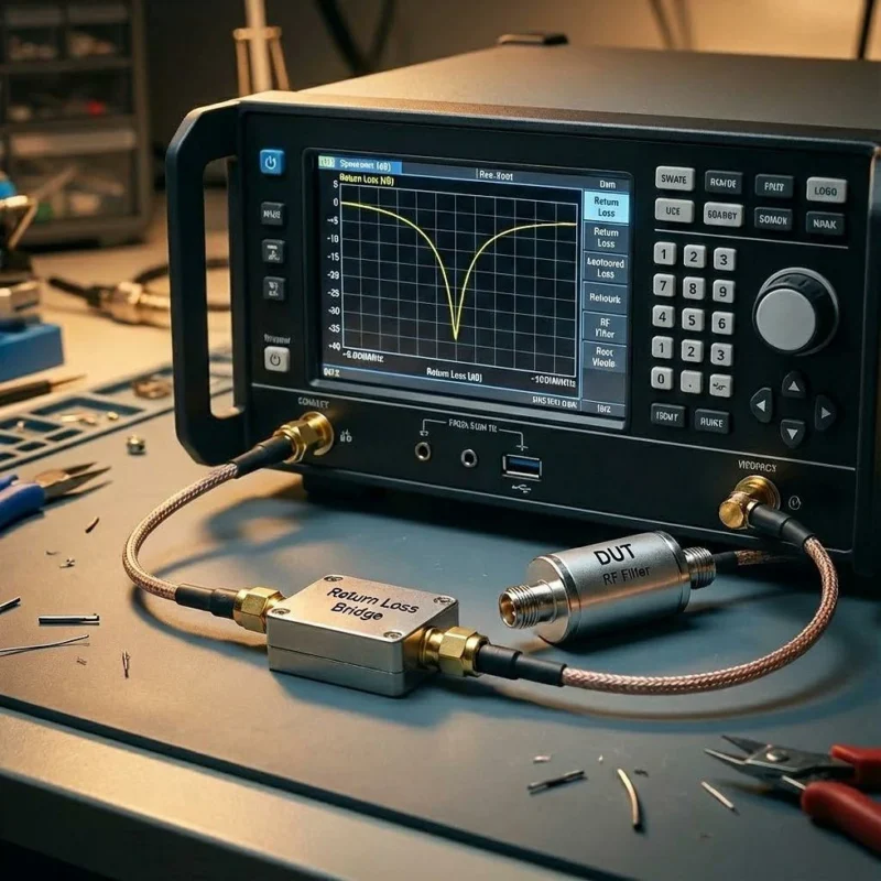
Mechanical inspection should come before RF measurement
Before connecting test equipment, the assembly itself needs to be checked.
Typical inspection points:
- connector appearance
- plating condition
- cable termination
- mating condition
- cable direction
A connector may pass an electrical test but still have a mechanical problem that appears during installation.
For production, both aspects need to be controlled.
MCX Connector Production Inspection Checklist
| Inspection Category | Check Content |
| Product information | Model, drawing, specification |
| Connector type | MCX male / female |
| Cable information | Cable model and length |
| Mechanical check | Mating and assembly condition |
| Appearance | Housing and plating inspection |
| Electrical check | Continuity test |
| RF check | VSWR, return loss, insertion loss |
| Production record | Test report and traceability |
What Information Is Needed for Custom MCX Cable Production?
Custom cable production usually starts with incomplete information.
A customer may provide only:
“Need MCX cable, 500 pieces.”
For manufacturing, this information is not enough.
The final product depends on several details:
- connector gender
- cable type
- cable length
- connector angle
- operating frequency
- testing requirements
A small missing detail can affect the sample approval process.
Custom MCX Cable Specification Template
| Specification | Required Information |
| Connector interface | MCX male / female |
| Cable model | RG178 / RG316 / Micro coax |
| Cable length | Finished assembly length |
| Connector orientation | Straight / right angle |
| Impedance | 50Ω system |
| Frequency range | Working frequency |
| Application | GPS, IoT, communication, testing |
| Test requirement | VSWR / insertion loss / other |
Final Considerations Before Selecting MCX
MCX is not selected simply because it is small.
In practical RF projects, the decision usually comes from several factors working together:
- available installation space
- cable routing condition
- production method
- testing requirement
- long-term reliability
A successful RF connection is not created by the connector alone.
The connector, cable, assembly process, and verification method all need to work together.
FAQ
Why is MCX commonly used in GPS equipment?
MCX provides a compact RF interface that fits well in GPS and GNSS products where antenna space is limited.
Is MCX smaller than SMA?
Yes. MCX is designed as a miniature RF connector, while SMA is generally larger and uses a threaded coupling structure.
