
Small RF products often face the same design problem: there is limited space around the circuit, but the connection still needs to remain stable.
A connector that works well on a laboratory bench may not fit inside a compact wireless device. The interface may be too large, the cable may not bend properly, or the connection may become unreliable after repeated assembly.
In these situations, SMB connectors are often considered as a compact RF connection option.
Typical uses include:
- GPS receiver modules
- Vehicle communication equipment
- Wireless sensor devices
- Embedded antenna systems
- Compact RF boards
In practical projects, the connector is rarely selected separately. The cable diameter, installation direction, operating frequency, and assembly method all influence the final choice.
For designers who are comparing different RF interfaces, checking a complete RF connector guide before selecting a part can reduce later redesign work.
SMB Connector Structure and Connection Method
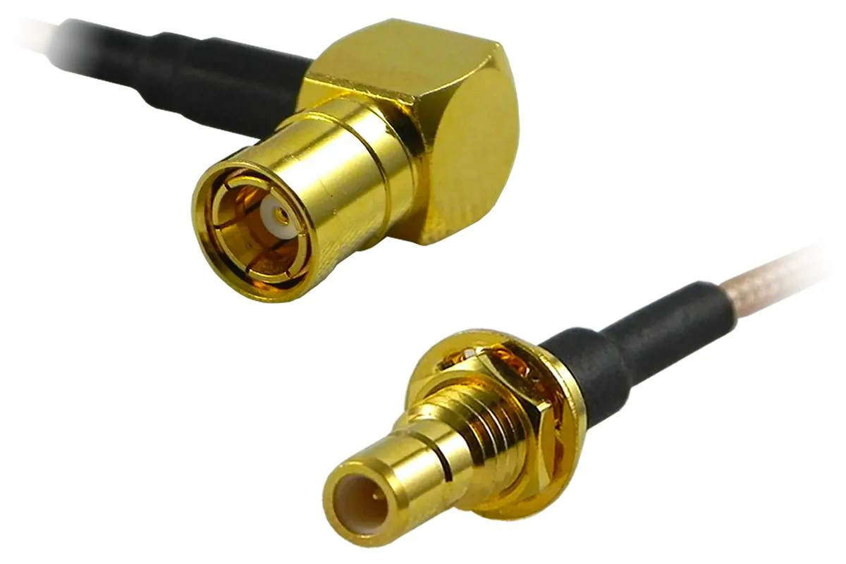
This custom SMB cable assembly combines a right-angle SMB connector with a bulkhead-mounted SMB interface. It is suitable for compact devices requiring controlled cable direction and secure panel installation.
Looking at an SMB connector from the outside, the structure appears simple. Internally, however, each part has a specific function.
The center contact carries the RF signal.
A basic SMB connector includes:
| Part | Function |
| Center pin or socket | Signal transmission |
| Outer conductor | Shielding and grounding |
| Insulator | Maintains electrical spacing |
| Housing | Provides mechanical protection |
| Cable termination section | Connects with coaxial cable |
For low-frequency applications, small differences in connector structure may not be obvious.
However, when the operating frequency increases, small mechanical variations can affect:
- VSWR
- Return loss
- Insertion loss
- Signal stability
This is also why SMB connectors used in RF equipment normally require consistent machining and assembly processes.
What Should Be Checked Before Choosing an SMB Connector?
A suitable SMB connector starts with the actual application rather than the connector catalog.
For example, a designer working on a GPS tracking device may focus on:
- Small installation area
- Flexible cable routing
- Lightweight assembly
A test equipment manufacturer may consider different factors:
- Repeat connection capability
- Stable measurement results
- Mechanical strength
The same SMB interface can have different requirements depending on where it is installed.
Before confirming a model, the following specifications should be reviewed:
| Item | Check Point |
| Frequency range | Confirm the connector supports the working band |
| Impedance | Match the RF system, commonly 50Ω |
| Cable type | Select suitable coaxial cable |
| Connector direction | Straight or right-angle structure |
| Mounting method | PCB, panel, or cable assembly |
| Working environment | Temperature and mechanical conditions |
One detail that is often overlooked is cable matching.
A compact connector combined with an unsuitable cable may create more problems than the connector itself. Cable diameter, shielding structure, and bending radius all affect the final assembly.
For this reason, SMB selection is usually completed together with cable selection instead of choosing the connector first.
Where Does SMB Fit Compared With Other RF Connectors?
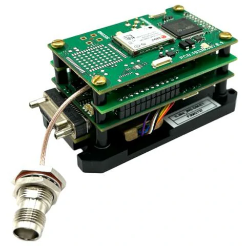
This application image shows an SMB coaxial cable assembly connecting a compact wireless PCB module to an externally mounted RF interface. Similar assemblies are used in GPS receivers, IoT terminals, embedded radios, and communication equipment
There are many RF connector families available, and each one solves a different design problem.
SMB is mainly used when space and assembly convenience are important.
SMB focuses on compact integration.
A simple comparison:
| Connector | Connection Style | Typical Use |
| SMB | Snap connection | Compact RF modules |
| SMA | Threaded connection | Test equipment and RF systems |
| BNC | Bayonet connection | Instruments and signal equipment |
| N Type | Threaded large interface | Outdoor RF systems |
There is no universal “better” connector. The correct choice depends on the working environment.
When a design requires smaller size and faster assembly, SMB can be a good option.
When mechanical locking is more important, designers may compare SMB with SMA connector comparison information before making the final decision.
Do Not Select SMB Connectors Only by Size
Miniature connectors are attractive because modern electronic products continue becoming smaller.
However, connector dimensions are only one part of the decision.
A complete evaluation should include:
- Electrical requirements
- Cable performance
- Mechanical installation
- Production method
- Testing requirements
For example, two SMB cable assemblies may use the same connector interface but show different RF results because of cable construction or assembly quality.
In production environments, consistency often matters as much as the nominal specification.
A connector that performs well in a single prototype also needs to maintain stable performance across repeated manufacturing batches.
How Do SMB Male and Female Connectors Match in RF Applications?
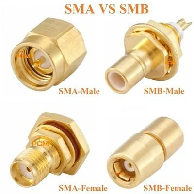
This image compares SMA male, SMA female, SMB male, and SMB female RF connectors, showing the differences in interface structure, coupling method, and connector size
In an RF project, choosing an SMB connector is not only about selecting the connector series. The interface direction is equally important.
A customer may provide a simple drawing showing an SMB interface, but for the supplier, “SMB” alone is not enough information. The production team still needs to confirm whether the required connector is male or female, where the connector will be installed, and how the cable will be routed.
This detail often affects the entire cable assembly.
For example, a short RF cable used inside a GPS module usually connects one PCB interface with another device interface. If the connector gender is selected incorrectly at the beginning, the finished cable may not match the customer’s equipment even though the cable length and electrical specifications are correct.
That is why SMB connector confirmation is normally completed together with the mechanical drawing.
Check the Difference Between SMB Male and SMB Female Connectors
The main difference between SMB male and SMB female connectors is the contact structure.
The SMB male connector uses a center pin, while the SMB female connector contains a socket contact that receives the pin.
Although this difference looks simple, it determines how two RF components can be connected.
An SMB male connector is often seen on cable ends.
The exposed center pin enters the female interface during connection, creating the signal path between the two components.
The female side is more commonly installed on:
- PCB boards
- RF modules
- communication devices
- embedded systems
Because the female connector is often part of the equipment, its mechanical position is usually decided during product design.
SMB Male Connector Structure
The center pin is one of the most important parts of an SMB male connector.
During assembly and transportation, the pin needs protection because even a small deformation can affect the mating condition.
For production inspection, suppliers normally pay attention to:
- Pin alignment
- Contact surface condition
- Plating quality
- Mechanical fit
In high-volume production, connector consistency is often more important than the performance of a single sample.
A prototype may work correctly, but unstable contact between batches can create problems after installation.
SMB Female Connector Structure
The SMB female connector is usually integrated into the equipment side.
For PCB applications, the designer needs to reserve enough space around the connector.
The actual design may involve:
- PCB layout position
- Connector height
- Nearby components
- Cable bending direction
- Assembly tools
This is especially important for compact products.
A connector may fit electrically but still create installation difficulties if the surrounding mechanical design is ignored.
SMB Male vs Female Selection Table
| Item | SMB Male Connector | SMB Female Connector |
| Contact structure | Center pin | Socket contact |
| Common location | Cable assembly end | PCB or equipment interface |
| Connection method | Insert into female side | Receive male contact |
| Main advantage | Easy cable connection | Suitable for equipment integration |
| Common mistake | Wrong pin interface | Incorrect PCB mounting selection |
| Inspection focus | Pin condition and alignment | Socket contact and mounting position |
How Does SMB Cable Selection Influence the Final RF Result?
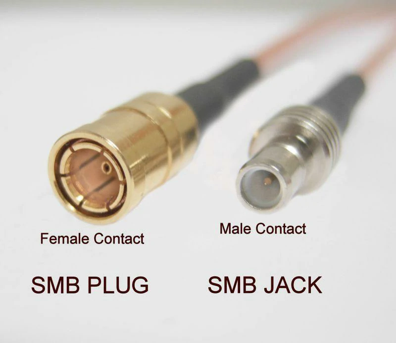
This SMB connector identification image explains the difference between an SMB plug and SMB jack by showing their center-contact structures. The coupling name and contact gender should both be checked before ordering.
The connector itself rarely determines the complete RF performance.
In many applications, the coaxial cable between two connectors has a greater influence on signal quality.
An SMB cable assembly usually contains:
- SMB connector
- Coaxial cable
- Termination structure
- Testing process
Changing the cable type may affect:
- Signal attenuation
- Flexibility
- Installation difficulty
- Working frequency
For example, a short cable inside a wireless module may prioritize flexibility and small diameter.
A longer RF connection may require lower loss characteristics.
There is no single cable that fits every SMB application.
Select SMB Cable Based on the Actual Installation Space
A common situation in electronic products is limited internal space.
The designer may know the required connector but still need to solve the cable routing problem.
A cable that is electrically suitable may not work mechanically.
The bending radius may be too large.
The cable diameter may interfere with nearby components.
The assembly process may become difficult.
Therefore, cable selection should consider both electrical and mechanical conditions.
How Do SMB Connectors Perform in Real RF Cable Assemblies?
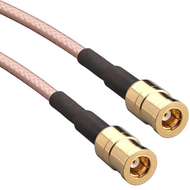
This image shows an SMB female-to-female RF cable assembly using flexible coaxial cable. It is suitable for compact wireless modules, embedded RF systems, GPS equipment, and internal signal connections.
When an RF cable assembly is tested, the connector is usually not the only thing being checked.
A customer may order an SMB cable because the interface matches their equipment, but after the sample arrives, the actual evaluation often involves much more than whether the connector can be plugged in.
The cable length, routing direction, termination method, and test results all become part of the acceptance process.
This situation is common in customized RF products.
A 100 mm SMB cable and a 500 mm SMB cable may use the same connector, but their application requirements can be completely different.
The shorter cable may be installed inside a compact module where flexibility matters more.
The longer cable may require better shielding and lower signal loss.
This is why SMB connector selection is normally considered together with the complete cable assembly.
Check the RF Path Instead of Looking at the Connector Alone
An SMB connector is only one section of the transmission path.
The complete RF route may include:
- Equipment interface
- SMB connector
- Coaxial cable
- Termination area
- Testing system
Any change in this path can influence the final measurement.
During production, some problems are not caused by the connector itself.
For example:
A cable stripping length that is slightly different can affect the connection quality.
An incorrect crimping process may create unstable contact.
A cable that is suitable mechanically may not provide the expected RF performance.
These details are difficult to judge only from appearance.
SMB Connector RF Testing Process
For RF cable assemblies, testing is usually performed after the assembly process is completed.
The common inspection items include:
Continuity
Used to confirm that the internal conductor is connected correctly.
VSWR
Used to check whether signal reflection is within the required range.
Return Loss
Used to evaluate reflected RF energy.
Insertion Loss
Used to measure signal attenuation through the assembly.
Different customers may set different requirements.
A cable used inside a consumer electronic device may focus on stable connection.
A cable used for RF testing equipment may require tighter electrical control.
How Should SMB and SMA Be Selected for Different Products?
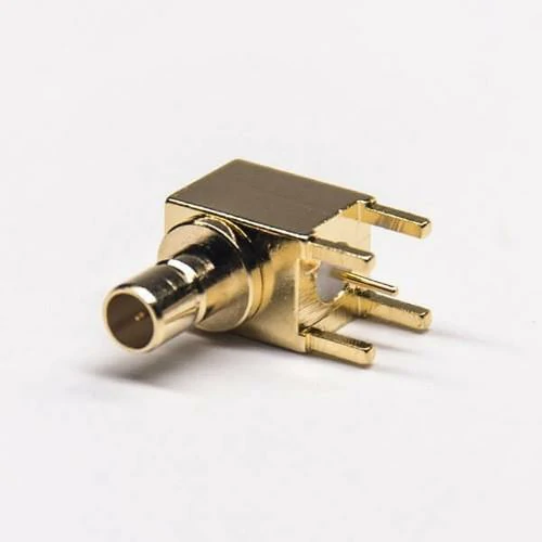
This right-angle SMB PCB connector provides a compact RF interface for circuit boards. Its angled structure can help control cable routing and reduce the installation height inside wireless and communication equipment.
SMB and SMA are often mentioned together because both are widely used in RF systems.
However, they solve different problems.
SMA was developed around a threaded connection structure.
The screw coupling provides a stronger mechanical connection, which is useful when the connector needs to remain fixed during repeated testing or operation.
SMB uses a snap connection.
The advantage is easier installation, especially when several RF connections are placed close together.
A design engineer choosing between them normally looks at the actual working environment.
For example:
A GPS module inside a vehicle may have very limited installation space. SMB can make cable routing easier.
A laboratory RF fixture may be connected and disconnected many times every day. SMA may be more suitable because of its threaded structure.
Neither connector is suitable for every application.
SMB vs SMA Practical Comparison
| Feature | SMB | SMA |
| Coupling method | Snap type | Thread type |
| Installation | Quick connection | Manual tightening |
| Size | Smaller | Larger |
| Mechanical locking | Moderate | Stronger |
| Typical position | Internal modules | Test equipment |
What Information Is Needed Before Custom SMB Cable Production?
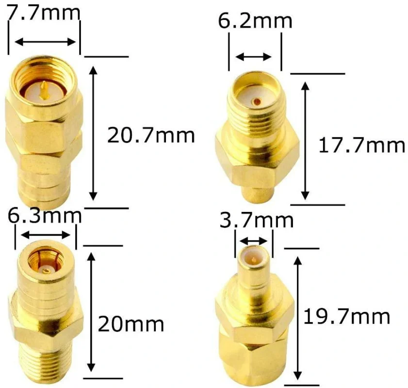
For standard SMB connectors, ordering is relatively simple.
Custom cable assemblies are different.
A supplier usually needs more information before starting production.
A product description such as:
“SMB cable, 200 mm”
does not define the complete requirement.
A complete specification helps avoid unnecessary sample modification.
SMB Cable Assembly Specification Form
| Field | Example Information |
| Connector Series | SMB |
| Connector Combination | Male to Female |
| Cable Model | RG178 / RG316 |
| Cable Length | Custom length |
| Connector Direction | Straight / Right angle |
| Impedance | 50Ω |
| Frequency Requirement | Application frequency |
| Temperature Range | Working environment |
| RF Test | VSWR / Loss requirement |
| Drawing | Mechanical reference |
How Are SMB Connectors Used in Compact Wireless Products?
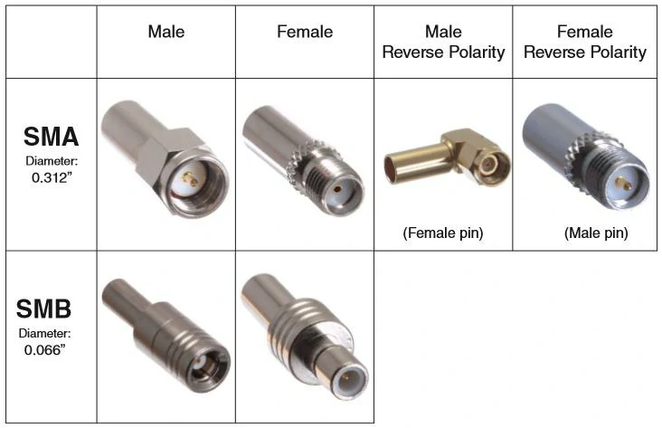
This comparison chart illustrates standard SMA male and female connectors, reverse-polarity SMA interfaces, and common SMB connector genders. It helps engineers distinguish the coupling structure from the center-contact gender.
Many modern electronic products place more functions into smaller spaces.
The available area for RF wiring is becoming limited.
Inside a compact device, the cable may need to pass around:
- Battery modules
- Control boards
- Antenna sections
- Mechanical structures
A connector that is electrically suitable but difficult to install can create problems during assembly.
SMB connectors are often selected because they provide a compact interface while keeping the connection process simple.
Common application examples include:
- Navigation equipment
- Wireless modules
- IoT terminals
- Automotive electronics
In these products, the cable assembly design is often completed together with the mechanical layout.
Why Direct SMB Cable Assemblies Can Be Better Than Extra Adapters
Adapters can solve interface differences.
However, adding more connection points also changes the RF path.
The cable length, connector direction, and interface combination can be designed according to the equipment structure.
SMB Connector Selection Notes for Engineers and Buyers
SMB connectors are a practical option for compact RF systems, but the connector itself is only part of the final solution.
During product development, the important factors usually include:
- Matching connector interface
- Selecting suitable coaxial cable
- Confirming mechanical installation
- Checking RF test requirements
- Maintaining production consistency
For customized projects, clear specifications at the beginning can save time during sampling and mass production.
A reliable SMB solution is created by matching the connector, cable, and application requirements together.
FAQ
Can SMB connectors be used for RF modules?
Yes. SMB connectors are frequently used in compact RF modules where installation space is limited.
Are SMB cables available with RG316?
Yes. RG316 is one of the commonly used coaxial cables for SMB cable assemblies.
Does cable length influence SMB RF performance?
Yes. Longer cables generally introduce more attenuation, so cable length should be considered with frequency requirements.
What tests are used for SMB cable assemblies?
Common tests include continuity, VSWR, Return Loss, and Insertion Loss.
