
N Type Connector Selection and Interface Identification
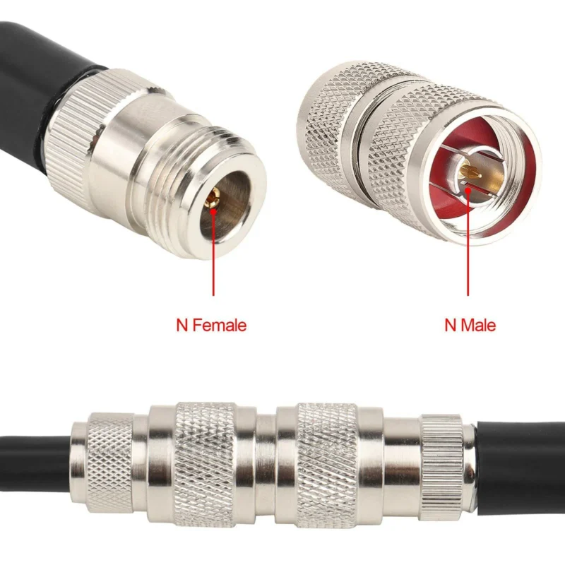
When selecting an RF connector, many engineers do not start with the connector itself. They usually start from the system requirement.
What frequency will the equipment run at?
Where will the cable be installed?
Will the connection stay indoors, or will it be exposed to rain, vibration, and temperature changes?
These questions often determine the connector choice before the product drawing is even reviewed.
The n type connector is a good example. It is not the smallest RF connector, and it is not designed for every application. However, when a project needs a strong mechanical connection, stable 50Ω transmission, and reliable outdoor performance, N connectors are still one of the options engineers consider first.
Before selecting a specific interface, engineers usually compare connector families first. A complete RF connector guide can help identify the differences between N, SMA, BNC, TNC, and other coaxial interfaces.
How Should You Select an N Type Connector for RF Systems?
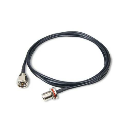
An N type coaxial cable assembly connecting male and female interfaces, commonly used with antennas, base stations, RF modules, and industrial wireless equipment.
A common mistake during purchasing is selecting an N connector only by appearance.
Two connectors may both be labeled as “N type”, but their actual performance can be different depending on frequency rating, cable compatibility, manufacturing accuracy, and installation method.
For example, an N connector used on an outdoor antenna feeder has different requirements from an N connector installed inside a laboratory test device.
The first one may need:
- stronger mechanical retention;
- better environmental protection;
- compatibility with larger coaxial cable.
The second one may focus more on:
- higher frequency accuracy;
- lower reflection;
- repeatable measurement performance.
The connector should match the entire RF path, not only the equipment port.
Explain N Type Connector from an RF Engineering View
The basic structure of an n type rf connector is simple:
- center contact;
- dielectric support;
- outer conductor;
- threaded coupling mechanism.
The design looks straightforward, but RF performance depends heavily on how accurately these parts are manufactured.
A small change in internal dimensions can affect impedance continuity. At lower frequencies, these differences may not be obvious. As frequency increases, the same mechanical tolerance can influence VSWR and signal reflection.
The N connector normally follows a 50Ω impedance design, making it suitable for many communication and measurement systems.
Its threaded coupling is one reason it remains popular in field applications.
Compared with push-on connectors, the threaded structure provides:
- stronger mating force;
- better resistance to vibration;
- reduced risk of accidental disconnection.
For outdoor antenna installations, this mechanical advantage can become more important than connector size.
A technician working on a rooftop antenna system may install the connector once and expect it to operate for years. In this situation, a secure threaded connection has practical value.
Match the Connector with the RF System Before Ordering
Before placing an order, RF engineers normally confirm several details together.
A connector cannot be evaluated separately from the cable and equipment.
For example:
A connector designed for a thin flexible cable may not fit a thicker low-loss feeder cable.
A panel connector may not replace a cable-end connector without changing the installation structure.
The following information should be confirmed before production:
| Selection Item | Why It Needs Confirmation |
| Connector gender | Ensures correct mating with equipment |
| Frequency range | Prevents operation beyond connector capability |
| Impedance | Maintains RF system matching |
| Cable type | Determines termination method and dimensions |
| Mounting style | Affects mechanical installation |
| Operating environment | Determines protection requirements |
Why Cable Selection Changes N Connector Performance
The cable connected to an N connector directly affects the final RF performance.
A connector installed correctly on the wrong cable can still create problems.
Engineers usually check:
- conductor diameter;
- dielectric size;
- shielding structure;
- cable loss;
- bending requirements.
For example, RG58 cable is flexible and easy to install, while larger low-loss cables are often selected for longer transmission distances.
Before selecting an N connector assembly, reviewing the RG cable guide helps engineers understand how cable construction influences RF transmission.
Understand Why N Connectors Remain Common in RF Infrastructure
Some connector designs become popular because they solve a very specific engineering problem.
Wireless Communication Equipment
Base stations and industrial wireless systems frequently require connectors that can handle continuous operation rather than temporary laboratory use.
RF Testing Equipment
Many test instruments use N interfaces because the connector provides a practical balance between mechanical strength and electrical performance.
Microwave and Industrial Systems
In industrial environments, equipment may experience vibration, temperature changes, or frequent maintenance. A threaded connector helps reduce connection problems.
The choice of an N connector usually comes down to system priorities.
If the project requires the smallest possible connector, other interfaces may be more suitable.
If the project requires:
- stable connection;
- outdoor reliability;
- reasonable power capability;
- long-term mechanical strength;
the N connector remains a practical solution.
How Do N Male and N Female Connectors Differ?
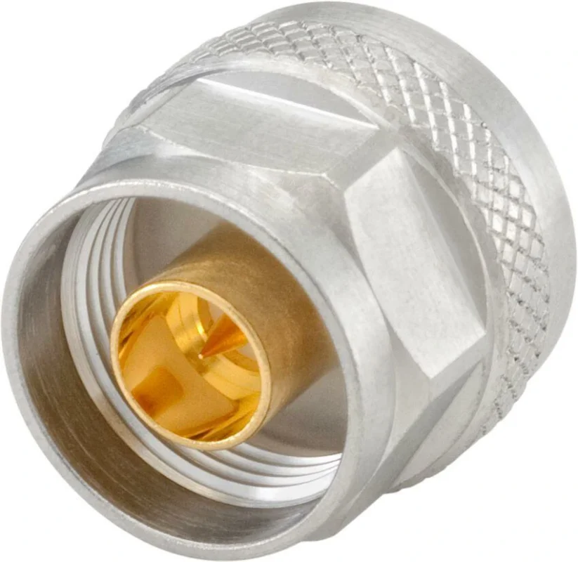
After selecting the N connector family, the next step is confirming the interface type.
Many purchasing issues are not caused by electrical problems. They happen because the wrong connector gender was selected.
The difference between N male and N female connectors is mainly related to the center contact and installation position.
Identify N Male Connector Features
The n male connector normally uses a center pin contact.
It is commonly found on cable assemblies.
Typical features include:
- center pin structure;
- rotating coupling nut;
- cable-side termination.
An N male connector is often used on:
- RF jumper cables;
- antenna cables;
- test cables;
- adapter cables.
During installation, the coupling nut is tightened onto the female interface while the cable body remains relatively stable.
This reduces stress on the cable during connection.
Identify N Female Connector Features
The n female connector uses a socket contact.
It is usually installed on fixed equipment.
Common applications include:
- antenna ports;
- RF modules;
- amplifiers;
- test equipment panels.
Because the connector is often mounted permanently, the mechanical mounting method is important.
Common mounting styles include:
- panel mount;
- bulkhead mount;
- flange mount.
The correct mounting structure helps maintain alignment and prevents mechanical damage during repeated connections.
N Male vs N Female Selection Table
| Field | N Male | N Female |
| Center Contact | Pin | Socket |
| Typical Installation | Cable side | Equipment side |
| Main Function | Connect cable assemblies | Provide equipment interface |
| Common Applications | RF jumper, feeder cable | Antenna port, RF device |
| Common Mistake | Wrong cable interface | Wrong equipment connection |
A simple way to avoid connector selection mistakes is to confirm three things together:
- Connector gender
- Cable type
- Equipment interface
Checking only the connector name is usually not enough.
In RF systems, every unnecessary adapter adds another transition point. Selecting the correct N male or N female connector at the beginning can simplify installation and reduce possible signal issues.
BNC Connector Guide for RF Applications
Walk into an RF laboratory and there is a good chance you will still find BNC connectors on the front panel of test equipment.
They may be connected to an oscilloscope, a signal generator, or an older measurement system that has been running for years.
BNC is not usually selected because it offers the highest frequency capability. In many cases, engineers choose it because it fits the working process.
A technician troubleshooting a circuit does not always want to spend time tightening threaded connectors. During development, connections may be changed repeatedly while checking different test points.
That is where the bayonet locking design becomes useful.
However, a common mistake is treating all BNC connectors as interchangeable.
Two connectors may have the same external shape but behave differently in an RF system because of differences in:
- impedance;
- cable compatibility;
- frequency capability;
- contact structure;
- manufacturing tolerance.
For this reason, BNC selection should begin with the application rather than the connector appearance.
How Should You Select a BNC Connector for an RF System?
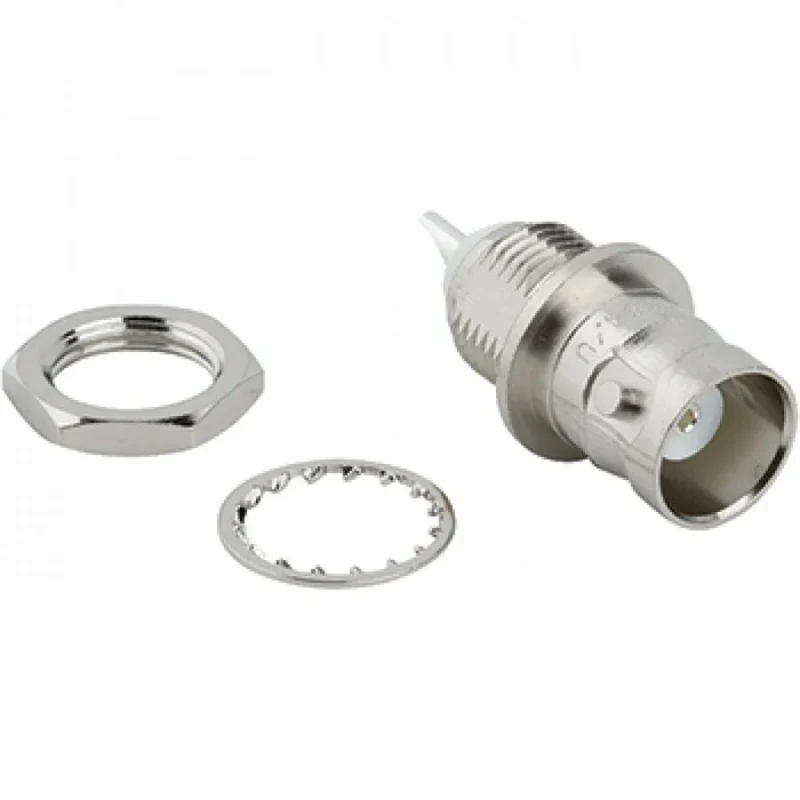
The first question is usually not “Which BNC connector looks correct?”
The better question is:
Where will this connector be installed, and what signal will pass through it?
A BNC connector used for laboratory measurement has a different working environment from one installed inside industrial equipment.
For example:
A test engineer may disconnect the same cable many times during one day. The connector needs to maintain stable contact after repeated operation.
A fixed equipment interface may stay connected for months. In this case, mechanical mounting and long-term reliability become more important.
The cable also changes the selection.
A connector designed for RG58 is not automatically suitable for RG174 or RG316. Even though all are coaxial cables, their dimensions are different.
The center conductor diameter, dielectric size, and shielding layer determine whether the termination will be reliable.
Before placing an order, engineers normally confirm several points:
| Item to Confirm | Engineering Reason |
| Cable model | Ensures correct mechanical assembly |
| Impedance | Avoids unnecessary signal reflection |
| Frequency requirement | Determines suitable connector design |
| Mounting method | Matches equipment structure |
| Operating environment | Affects material and plating choice |
A BNC connector is often a good choice when fast access and reliable connection are more important than extreme high-frequency performance.
Why Does BNC Still Appear in Modern RF Equipment?
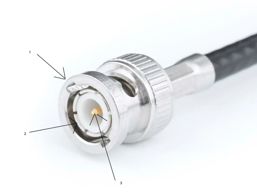
Connector technology changes, but laboratory habits change much slower.
Many measurement instruments are designed around BNC interfaces because engineers are already familiar with the connection method.
The push-and-twist locking action provides a simple operation:
- Align the connector.
- Push into position.
- Rotate the locking ring.
No special tool is required.
This is useful in environments where engineers frequently change cables while debugging a design.
A typical BNC coaxial connector contains several basic parts:
- Center contact
- Insulator
- Outer conductor
- Connector body
- Bayonet locking mechanism
The electrical principle is the same as other coaxial interfaces.
The inner conductor carries the signal.
Where Are BNC Connectors Commonly Used?
BNC connectors are often associated with measurement equipment because that is where their advantages are most obvious.
Oscilloscope Connections
Oscilloscopes commonly use BNC interfaces for signal input.
During electronic development, engineers may need to check:
- waveform changes;
- signal timing;
- noise level;
- output stability.
The ability to quickly change cables makes BNC practical for this type of work.
Signal Generator Interfaces
Signal generators also frequently use BNC ports.
The connector itself is only one part of the transmission path.
The complete connection includes:
Signal source → cable → BNC connector → device under test
If the cable or connector does not match the system requirements, the measurement result may be affected.
Laboratory RF Testing
In RF development, BNC connectors are often used for lower-frequency test connections and auxiliary measurement paths.
When the operating frequency increases, engineers usually compare BNC with other connector families such as SMA or N-type.
The choice depends on the actual requirement rather than the connector popularity.
How Do BNC Male and Female Connectors Match in a System?
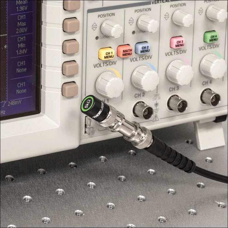
BNC connectors are commonly installed on oscilloscopes and laboratory instruments because their bayonet locking design allows quick and repeatable test connections.
A BNC connection always involves two sides:
- BNC male connector
- BNC female connector
The male side normally connects to the cable.
The female side is commonly installed on equipment.
Although they have different structures, both parts must maintain the same coaxial geometry after mating.
An incorrect match can cause problems before the signal even reaches the RF system.
Common mistakes include:
- selecting the wrong gender;
- choosing an unsuitable cable termination;
- confusing connector appearance with electrical specification.
How Should You Identify a BNC Male Connector?
A BNC male connector normally has a visible center pin.
The locking ring around the body allows the connector to attach to the female interface.
Typical applications include:
- test cables;
- oscilloscope cables;
- RF jumper cables.
When selecting a BNC male connector, the important information is usually not only the connector model but also the cable being attached.
For example:
A small flexible cable assembly may require a compact termination design, while a thicker coaxial cable requires a different mounting structure.
How Should You Identify a BNC Female Connector?
The BNC female connector provides the receiving interface.
It is commonly found on:
- instruments;
- equipment panels;
- test fixtures;
- communication devices.
For panel applications, mechanical mounting is often an important consideration.
A connector may need:
- panel thickness compatibility;
- proper fixing method;
- suitable environmental protection.
BNC Male vs Female Selection Table
| Comparison | BNC Male | BNC Female |
| Contact | Center pin | Socket contact |
| Typical Location | Cable end | Equipment interface |
| Main Function | Signal transmission connection | Signal receiving interface |
| Locking Method | Rotating bayonet ring | Matching bayonet slot |
| Selection Focus | Cable compatibility | Equipment mounting |
Inspecting and Specifying BNC Connectors for Real RF Projects
A BNC connector problem is not always easy to notice at the beginning.
In many cases, the connector can be plugged into the equipment normally. The locking mechanism works, the signal appears, and the system seems fine.
The problem may only appear later:
- measurement results are unstable;
- the signal level changes after reconnecting;
- different cable assemblies show different test results.
This is why experienced RF engineers usually do not judge a BNC connector only by appearance.
The connector needs to be considered together with the cable, equipment port, and operating frequency.
What Details Are Worth Checking Before Using a BNC Connector?
The first check usually happens before the connector enters the test system.
A technician may look at:
- connector appearance;
- mechanical fit;
- cable termination;
- contact condition.
A good BNC connection should feel consistent.
The male connector should slide into the female side without excessive force.
After rotation, the bayonet structure should hold the connection firmly.
A simple inspection can prevent many common problems.
| Check Area | Common Finding |
| Locking ring | Loose or difficult rotation |
| Center contact | Incorrect position or contamination |
| Connector body | Damage during handling |
| Cable joint | Weak termination |
| Surface plating | Wear or oxidation |
For products used in laboratory environments, repeated connection cycles should also be considered.
A connector that works once may not perform the same way after hundreds of mating operations.
Testing BNC Connector Performance in RF Systems
Mechanical inspection only confirms that the connector can be assembled.
For RF applications, electrical verification becomes more important.
A BNC connector is part of a complete transmission path.
The actual signal path may look like:
Signal generator → BNC cable → Adapter → Device under test → Analyzer
Any interface in this path can influence the measurement result.
Continuity Test Comes First
Continuity testing is usually the basic inspection step.
It confirms:
- the center conductor is connected;
- the shield path is complete;
- there is no unexpected short circuit.
For production batches, this test helps identify assembly mistakes before shipment.
However, continuity only tells whether the circuit is connected.
It does not show whether the RF performance is suitable.
Why VSWR Matters in BNC Applications
When engineers check BNC performance at RF frequencies, VSWR is one of the parameters that cannot be ignored.
A connector may physically fit the equipment but still create reflection problems if the impedance matching is not correct.
The possible causes include:
- incorrect connector design;
- unsuitable cable selection;
- poor termination process;
- impedance mismatch between components.
For this reason, RF engineers often evaluate the complete assembly rather than testing the connector separately.
Understanding Return Loss During RF Testing
Return loss provides another view of signal reflection.
A better-matched connection usually produces lower reflected energy.
In practical projects, return loss is affected by many parts:
- connector;
- cable;
- adapter;
- equipment interface.
A BNC connector with good machining quality can still show poor results if it is connected with an unsuitable cable or adapter.
BNC Connector Inspection Standard
| Item | Inspection Method | Purpose |
| Model confirmation | Specification review | Avoid wrong product selection |
| Connector gender | Visual check | Confirm interface matching |
| Cable compatibility | Assembly check | Ensure proper termination |
| Impedance | Datasheet verification | Maintain RF matching |
| Mechanical locking | Manual operation | Check connection stability |
| Continuity | Electrical test | Confirm circuit connection |
| VSWR | RF measurement | Evaluate reflection |
| Return Loss | Network analyzer | Check matching quality |
Defining BNC Cable Assemblies Before Production
Many BNC projects fail during communication because the initial specification is incomplete.
For example:
“Need 100pcs BNC cable”
This description does not tell the manufacturer enough information.
The final product could be completely different depending on:
- cable type;
- cable length;
- connector direction;
- impedance;
- testing requirement.
Information Needed for Custom BNC Cable Production
A complete request normally includes:
Connector Side
Example:
- BNC male to BNC female;
- straight type;
- right-angle type;
- panel mount version.
Cable Side
Common coaxial options include:
- RG58;
- RG174;
- RG316;
- RG59;
- RG6.
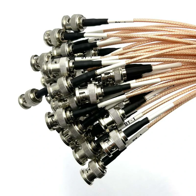
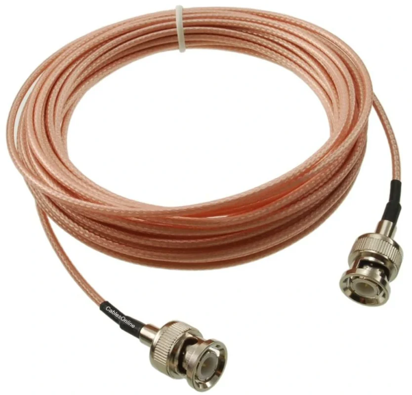
Custom BNC coaxial cable assemblies manufactured with specified connector types, cable lengths, impedance, labeling, and testing requirements.
Cable selection changes the final characteristics.
For example:
RG316 is often selected when flexibility and compact size are needed.
RG58 is usually chosen when a stronger cable structure is acceptable.
RG59 and RG6 are commonly used in 75Ω video-related systems.
BNC Custom Specification Sheet
| Specification | Required Information |
| Connector Type | Male / Female |
| Connector Angle | Straight / Right Angle |
| Cable Type | RG58 / RG174 / RG316 / RG59 |
| Cable Length | Customer requirement |
| Impedance | 50Ω / 75Ω |
| Frequency Range | Working frequency |
| Termination | Crimp / Solder |
| Test Requirement | Continuity / VSWR / Return Loss |
Choosing BNC for Current RF Applications
BNC connectors remain useful because they fit many practical working environments.
They are common where engineers need:
- quick replacement;
- simple connection;
- easy maintenance.
Typical applications include:
- electronic testing;
- laboratory instruments;
- broadcast equipment;
- signal monitoring systems.
Final Selection Notes
A suitable BNC connector is not simply the one that can be connected.
The better choice comes from matching several conditions:
- correct impedance;
- suitable cable;
- proper frequency range;
- reliable mechanical structure;
- verified RF performance.
For standard applications, BNC remains a practical and efficient interface.
For higher-frequency or precision microwave systems, engineers may need to compare it with other RF connector families.
The final decision should follow the requirements of the complete system rather than the connector name alone.
FAQ
Can 50Ω and 75Ω BNC connectors be mixed?
They may physically connect, but impedance differences can affect signal performance.
Is BNC still useful for RF testing?
Yes. Many test instruments and laboratory systems continue to use BNC interfaces.
Does cable type affect BNC performance?
Yes. Cable diameter, impedance, and construction influence the final assembly result.
Should BNC assemblies be tested before shipment?
For important RF applications, continuity, VSWR, and return loss testing are commonly considered.
When should SMA replace BNC?
When frequency, size, or RF performance requirements exceed the practical range of BNC.
