
What Should You Check Before Choosing an SMA Cable?
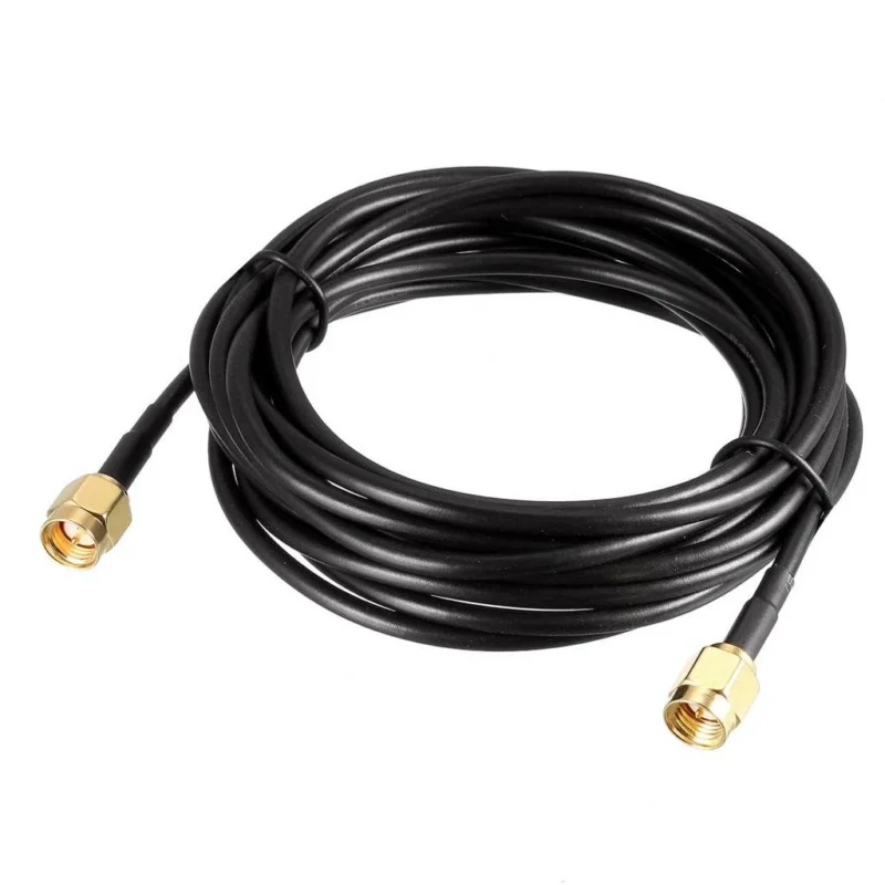
In many RF projects, the first question is not “which SMA cable should I buy?”
The real question is usually:
Where will this cable be installed, and what signal conditions will it face?
A cable connecting an antenna module inside a wireless device has very different requirements from a cable used for repeated VNA measurements in a laboratory.
The connector style may look similar, but the internal cable structure, length, and manufacturing process can change the final RF result.
An SMA cable normally combines three parts:
- SMA connector
- Coaxial cable
- Termination process
The connector provides the mechanical interface, while the coaxial section determines how the RF signal travels.
During product development, many engineers first confirm the connector interface and then evaluate the cable selection. A basic understanding of different RF interfaces can be found in this RF connector guide.
For this reason, SMA cable selection should start from the application rather than the connector appearance.
How Does the Internal Structure Influence SMA Cable Performance?
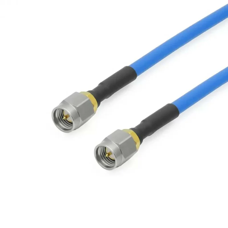
A coaxial cable looks simple from the outside, but its internal construction decides how stable the RF signal remains.
Inside a typical SMA coaxial cable, several layers work together.
Shielding Layer
The shield surrounds the signal path and reduces interference.
In practical installations, shielding becomes important when cables are placed near:
- Switching power supplies
- Multiple wireless modules
- Industrial equipment
- Other RF transmission lines
Poor shielding can introduce unwanted noise into measurements or communication systems.
Why Do Frequency and Cable Length Need to Be Considered Together?
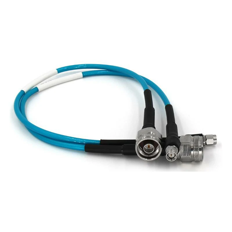
These custom RF coaxial cable assemblies use different connector combinations to meet the interface, cable length, frequency, and installation requirements of communication and testing systems.
A common misunderstanding is that an SMA cable with a suitable connector can work at any frequency.
The connector interface is only one part of the system.
As frequency increases, small differences become more noticeable:
- Connector machining accuracy
- Cable loss
- Assembly quality
- Signal reflection
For example, a short SMA cable used for a 2.4 GHz wireless module may have completely different requirements from a cable used for microwave testing.
Cable length also changes the result.
A longer cable means:
- More transmission loss
- Greater phase change
- More installation considerations
In many RF designs, the target is not simply choosing the shortest cable, but choosing a length that allows proper installation without unnecessary signal degradation.
When selecting the cable material, engineers often compare different coaxial structures through a coaxial cable selection reference because cable construction directly affects attenuation and flexibility.
Which SMA Cable Shape Works Better: Straight or Right Angle?
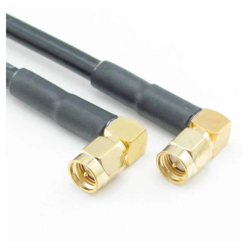
Connector direction is a small detail during design review, but it often becomes a problem during assembly.
Straight SMA Cable
Straight connectors are commonly selected when there is enough space around the connection point.
Typical advantages:
- Simple routing
- Easy installation
- Convenient for repeated testing
They are frequently used in:
- Laboratory equipment
- RF test setups
- Communication devices
How Do SMA Male and SMA Female Cables Match Different Devices?
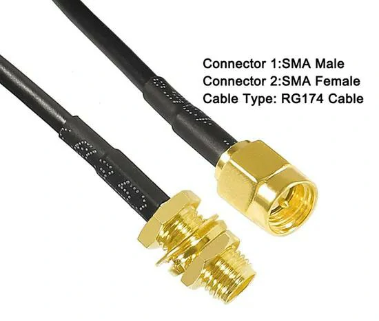
This SMA male to SMA female RG174 cable assembly provides a compact RF connection for wireless modules, antennas, communication devices, and space-limited electronic equipment.
Connector gender is one of the details that must be confirmed before production.
A cable may have the correct frequency rating and impedance, but it still cannot be installed if the connector interface is wrong.
SMA Male Cable
Typical structure:
- Center pin
- External thread
- Coupling nut
Common applications:
- Antenna ports
- RF adapters
- Test equipment
SMA Female Cable
Typical structure:
- Socket contact
- Internal thread
Common applications:
- PCB modules
- Communication devices
- Equipment panels
Before ordering, it is recommended to confirm:
| Item | Example |
| Connector side A | SMA male |
| Connector side B | SMA female |
| Cable direction | Straight / Right angle |
| Cable length | Custom requirement |
| System impedance | 50 ohm |
Small interface differences are often the reason why prototype cables need to be remade.
SMA Cable Selection Reference Table
| Check Item | Common Options | Why It Matters |
| Connector Type | SMA male / SMA female | Ensures mechanical compatibility |
| Cable Structure | Flexible / Semi-rigid / Low loss | Balances installation and RF performance |
| Frequency Range | MHz / GHz applications | Determines usable signal range |
| Cable Length | Custom length | Controls loss and installation space |
| Installation | Indoor / Outdoor / Device internal | Affects material selection |
| Main Purpose | Antenna / Testing / Module | Defines design priority |
SMA Cable Selection Summary
Choosing an SMA cable is not only about finding a matching connector.
The final performance depends on:
- How the cable is built
- Where it is installed
- What frequency it carries
- How accurately it is assembled
A suitable SMA cable should fit the complete RF system, from the equipment interface to the final application environment.
Matching SMA Cable Types With Real Installation Conditions
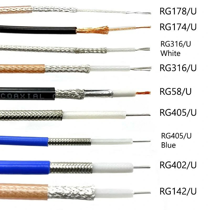
This image compares RG178, RG174, RG316, RG58, RG405, RG402, and RG142 coaxial cable structures, helping engineers evaluate cable diameter, shielding, flexibility, and application requirements.
Which SMA Cable Works Better Depends on Where It Will Be Installed
In many projects, the cable specification is not decided at the beginning.
A customer may first provide the equipment interface:
“Need SMA connection.”
At this stage, the information is usually not enough.
The same SMA interface can be used in different situations:
- A wireless module inside a small enclosure
- A communication antenna installed outdoors
- A laboratory test setup
- A prototype board requiring repeated connection
The connector only tells us how the cable connects. The cable itself needs to match the working environment.
For example, a flexible cable may be preferred when the assembly team needs to route the cable around other components. A thicker coaxial cable may be considered when signal loss becomes a bigger concern.
This is also why RF cable selection usually starts with the application condition instead of the connector model.
Why Do Engineers Choose RG316 for Compact RF Equipment?
A common situation in electronic equipment is limited installation space.
Inside a compact device, there may already be:
- PCB components
- Battery space
- Shielding covers
- Mechanical supports
The cable often needs to pass through a narrow area without putting pressure on the connector.
This is where RG316 SMA cable assemblies are frequently considered.
The smaller cable diameter makes routing easier, especially for:
- GPS equipment
- Wireless modules
- IoT devices
- Embedded communication products
During sample development, engineers often prefer this type of cable because changes to the mechanical layout are easier to handle.
However, flexibility is not the only factor.
When the cable becomes longer or the frequency increases, attenuation needs to be reviewed together with the installation requirement.
A short internal connection and a long RF transmission path are two different applications, even if both use SMA connectors.
For more details about coaxial cable structures and common cable families, engineers can refer to the coaxial cable selection guide.
Where Does RG58 Become a Better Option?
RG58 is still widely used because it provides a practical balance between handling and performance.
Compared with smaller flexible cables, RG58 has a larger cable diameter.
This brings some differences:
- Easier manual installation
- Stronger mechanical structure
- Better handling during assembly
It is commonly used in applications where the cable does not need to fit into extremely tight spaces.
Typical examples include:
- Antenna connections
- Communication equipment
- Industrial RF systems
- General signal transmission
During purchasing, some customers compare only the unit price of different cables.
In actual use, the better comparison is usually:
“Will this cable maintain the required performance after installation?”
A cable that is easy to purchase but difficult to install or unsuitable for the operating environment may create additional testing and replacement work later.
When Is RG142 Selected Instead of Flexible Cable?
Some RF equipment operates in environments where temperature and mechanical stability matter more than cable flexibility.
RG142 is often considered for these conditions.
Examples include:
- Equipment exposed to heat
- Industrial control systems
- Long-term installed RF connections
- Applications requiring stronger cable structure
Compared with RG316, RG142 is not designed mainly for tight routing.
The decision is usually based on project requirements:
If the cable needs to move around components during assembly, flexibility may be preferred.
If the cable will remain fixed in a demanding environment, a stronger structure may be more suitable.
There is no universal “best” SMA cable. The correct selection depends on what the cable experiences after installation.
SMA Cable Type Selection Matrix
| Working Condition | Possible Cable Choice | Main Reason |
| Limited internal space | RG316 SMA cable | Easier routing and bending |
| General equipment connection | RG58 SMA cable | Balanced mechanical handling |
| Higher temperature environment | RG142 SMA cable | Better environmental capability |
| Long-distance RF path | Low-loss coaxial cable | Reduces transmission loss |
| Frequent laboratory connection | Stable RF test cable | Improves repeatability |
| Compact antenna system | Flexible coaxial cable | Supports tight installation |
Why Are SMA to SMA Cables Commonly Used in RF Testing?
A large number of RF measurement setups use SMA to SMA cables.
The reason is straightforward:
Many instruments and modules already provide SMA ports.
Common connection examples include:
- Signal source to receiver
- Antenna module to evaluation board
- RF instrument to test fixture
- Wireless module testing
Before making a jumper cable, the connector combination still needs confirmation.
A request like:
“SMA cable required”
usually leaves several questions unanswered:
- Male or female?
- Same connector on both sides?
- Straight or right-angle?
- Required length?
- Frequency range?
These details are normally confirmed before production because changing them after assembly can affect the whole design.
Which Measurements Are Useful Before SMA Cable Delivery?
A cable may look normal from the outside and still need electrical verification.
Common inspection items include:
VSWR Check
VSWR helps identify whether the cable connection has excessive reflection.
Problems may come from:
- Connector mismatch
- Poor assembly
- Damaged interface
Return Loss Measurement
Return loss provides another way to evaluate reflected signal.
It is especially useful when the cable is used in systems where signal stability matters.
For projects involving RF reflection analysis, the return loss guide can help explain the relationship between reflection and connection quality.
Insertion Loss Measurement
Insertion loss shows how much signal is reduced when passing through the cable.
The result changes with:
- Cable length
- Frequency
- Cable structure
- Connector design
For short jumpers, the effect may be small.
For longer RF paths, it becomes a key acceptance parameter.
What Information Helps Avoid Repeated SMA Cable Samples?
For customized orders, unclear information is one of the main reasons for sample modification.
A useful specification normally includes:
- SMA connector on both ends
- Cable type
- Cable length
- Frequency range
- Impedance
- Test requirements
For example:
SMA male to SMA female / RG316 / 300 mm / 50Ω / VSWR test required
provides much more useful information than:
Need SMA cable sample.
Clear requirements help both the customer and manufacturer evaluate the correct solution faster.
Practical SMA Cable Applications and Custom Production Notes
Where Do SMA Antenna Cables Usually Appear in Real Products?
In a finished electronic product, the RF module and antenna are not always placed next to each other.
Mechanical engineers often move the antenna position because of:
- Housing design
- Signal coverage requirements
- PCB layout
- Heat sources
- Internal component arrangement
The cable between these two points becomes the bridge.
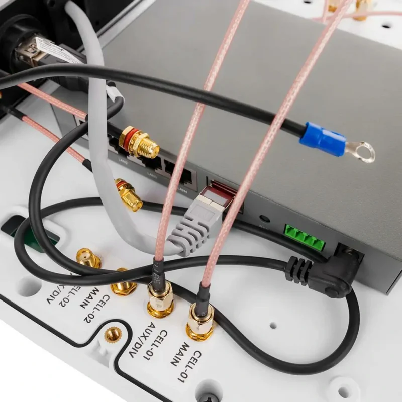
A typical example is a wireless gateway. The RF module may be fixed near the main board, while the antenna needs to be positioned closer to the outside of the enclosure.
In this situation, an SMA antenna cable provides a flexible connection without changing the PCB structure.
Similar situations can be found in:
- GPS receivers
- Industrial wireless controllers
- Cellular communication devices
- Test equipment
- Remote antenna systems
The cable length is usually discussed after the mechanical layout is confirmed. A few centimeters can make a difference when the cable needs to pass around brackets, shielding covers, or other components.
What Problems Can Appear When SMA Antenna Cable Selection Is Incorrect?
A cable may look correct during assembly but create issues during testing.
Some common situations include:
The cable reaches the antenna but creates unnecessary loss
A longer cable can solve a mechanical problem, but the additional length also changes the signal path.
For example:
A 200 mm connection inside a device and a 2 m connection to an external antenna should not be evaluated in the same way.
The connector fits but the cable direction is unsuitable
A straight SMA connector may work electrically, but a right-angle version could be a better mechanical choice.
This is especially common in:
- Compact housings
- Edge-mounted modules
- Space-limited products
The cable works in a prototype but changes during mass production
Prototype assembly is often flexible.
During volume production, the same cable needs to handle:
- Repeated installation
- Operator assembly
- Mechanical tolerance
- Long-term usage
This is why cable selection should consider the production environment, not only the first sample test.
Why Do Customers Request Custom SMA Cable Assemblies?

Many customers start with a standard cable but later move toward customization.
The reason is usually not simply changing the connector.
A custom SMA cable may involve:
- Different connector combinations
- Special cable length
- Specific bending direction
- Limited installation space
- Required test standards
For example, a customer may have an RF board with an SMA female port and an antenna that requires an SMA male connection.
A standard cable may be close to the requirement, but the customer may still need:
- A specific length
- A specific connector angle
- A defined test report
In these cases, a customized assembly avoids using multiple adapters or modifying the equipment design.
What Information Should Be Confirmed Before SMA Cable Production?
A simple product description is usually not enough for a customized cable.
For example:
“Need SMA cable, 500 pcs”
does not define:
- Which SMA interface?
- What cable type?
- What frequency?
- What length tolerance?
- What inspection standard?
Before production, the information normally needs to be clarified.
A practical specification usually includes:
Connector information
- SMA male or female
- Standard SMA or reverse polarity SMA
- Straight or right angle
Cable information
- Cable model
- Outer diameter
- Length
- Flexibility requirement
Electrical information
- Impedance
- Frequency range
- VSWR requirement
- Insertion loss limit
Clear specifications reduce repeated sample adjustments and make production evaluation faster.
How Can Buyers Choose the Right SMA Cable Supplier?
Price is usually one part of the purchasing decision, but RF cable projects often involve more than unit cost.
A supplier should be able to support:
Specification Communication
The supplier should understand the difference between:
- SMA male and female
- Cable diameter
- Frequency requirement
- Testing method
Custom Production
For different projects, the supplier may need to handle:
- Small samples
- Engineering confirmation
- Modified drawings
- Batch production
FAQ
Can an SMA cable be used for every antenna system?
No.
The cable needs to match:
- Frequency range
- Connector interface
- Impedance
- Installation condition
Does a longer SMA cable always reduce signal quality?
A longer cable usually creates more loss, but the actual impact depends on:
- Cable type
- Frequency
- Application requirement
The correct length is usually selected according to the complete system design.
