
How Should You Define an RF Cable Assembly Before Ordering?
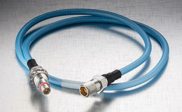
Blue RF cable assembly manufactured with coaxial connectors for stable signal transmission. Cable type, connector combination, frequency range, and length can be selected according to the application.
When an RF system starts moving from prototype testing to actual production, the cable connection is often one of the parts that receives less attention than the antenna or RF module.
However, the cable assembly sits directly in the signal path. A poor connection, unsuitable cable structure, or inconsistent termination process can affect the entire system performance.
An RF cable assembly is not simply a coaxial cable with connectors attached. It is a complete RF transmission component manufactured according to specific electrical and mechanical requirements.
A typical assembly includes:
- Coaxial cable
- Connector on each end
- Cable length specification
- Connector orientation
- Shielding structure
- Protective jacket
- Electrical inspection requirements
For example, an SMA cable assembly used inside a wireless device may only be several centimeters long, while a cable used between an outdoor antenna and communication equipment may require stronger mechanical protection and lower signal loss.
The correct selection depends on how the cable will work inside the final system.
Before requesting a quotation, engineers normally prepare basic information such as:
- Required frequency range
- Cable impedance (usually 50 ohm in RF systems)
- Connector type
- Cable length
- Installation environment
- Expected attenuation
- Testing requirements
Many design problems happen because only the connector model is provided while the cable performance requirement is ignored. A connector may fit mechanically, but the complete assembly may still fail to meet the RF target.
For engineers who are selecting connectors first, reviewing a complete RF connector guide can help avoid common mistakes related to interface type, impedance, and frequency range.
Separate Cable Assemblies from Raw Coaxial Cables
During purchasing, engineers often need to decide whether they should buy raw coaxial cable or a finished cable assembly.
These two products solve different problems.
A raw coaxial cable is mainly a material used for further processing. The buyer needs to handle:
- Connector installation
- Cable cutting
- Crimping or soldering
- Electrical verification
This approach is suitable for companies that already have RF production capability.
An RF cable assembly is ready for installation. The supplier completes the manufacturing steps and provides a finished connection solution.
For example:
A customer needs a 500 mm cable between an RF module and antenna.
The actual requirement may include:
- One SMA male connector
- One IPEX connector
- 50 ohm impedance
- Specific bending direction
- Tested insertion loss value
Simply purchasing 500 mm of coaxial cable does not solve the complete requirement.
In many compact electronic devices, flexible coaxial cables are selected because installation space is limited. Before choosing the assembly structure, engineers often compare cable diameter, loss, and flexibility. A review of RG316 coaxial cable characteristics can help determine whether a small-diameter cable is suitable for the design.
Explain Why Assembly Quality Affects RF Performance
The final performance of an RF cable assembly depends not only on the cable specification but also on how the product is manufactured.
Several details can influence the result.
may increase signal reflection or create unstable performance.
Cable routing and mechanical stress
RF cables are often installed in limited spaces.
Repeated bending, excessive pulling force, or incorrect routing may change the internal cable structure.
For flexible cables, maintaining the recommended bending radius is important because deformation can affect impedance consistency.
Production testing
A finished RF cable assembly should normally be checked before shipment.
Typical inspection items include:
- Appearance inspection
- Connector fitting check
- Cable length verification
- Continuity test
- VSWR measurement
- Insertion loss testing
For high-frequency applications, testing the finished assembly is more meaningful than relying only on the specification of the individual cable or connector.
Match Cable Type with Frequency and Environment
Different coaxial cables are designed for different applications.
Flexible RF cable assemblies
Flexible cables are commonly used where installation freedom is important.
Typical examples include:
- Wireless modules
- Antenna connections
- Portable devices
- Internal equipment wiring
The advantage is easy installation. Engineers can route the cable around tight spaces without requiring complex mechanical structures.
The trade-off is that very small flexible cables usually have higher attenuation compared with larger low-loss cables.
Low-loss RF cable assemblies
When signal distance increases, cable loss becomes a more important factor.
Low-loss assemblies are often considered for:
- Communication systems
- Antenna feeder connections
- Test equipment
- Microwave applications
A longer cable route means more attention should be paid to attenuation values at the operating frequency.
For this reason, selecting an RF cable assembly is not only about choosing a connector model. The cable type, length, and frequency requirement must work together.
Which Cable and Connector Combination Fits Your RF System?
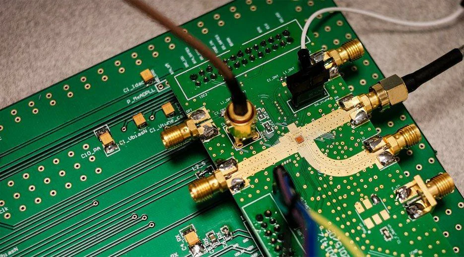
RF test board equipped with several SMA connectors and coaxial cable connections. Proper cable routing, connector matching, and termination quality help maintain stable high-frequency performance.
When customers ask for an RF cable assembly, the first information they usually provide is the connector type.
For example:
“Need SMA cable.”
“Need N-Type antenna cable.”
“Need a 1 meter RF cable.”
These descriptions are useful, but they are not enough to make the correct assembly.
The connector is only the interface. The cable inside the assembly decides many of the actual characteristics.
A 30 cm SMA cable and a 3 meter SMA cable may use the same connector but require completely different cable structures.
The same situation happens with frequency.
A cable assembly working at 900 MHz may have very different requirements compared with one used at 6 GHz.
Before production, it is better to confirm the complete requirement:
- Working frequency
- Cable length
- Installation position
- Connector direction
- Space limitation
- Expected signal loss
This avoids a common problem: the cable fits the equipment, but the RF performance does not meet the system requirement.
How Do You Select the Right Cable Type for an RF Assembly?
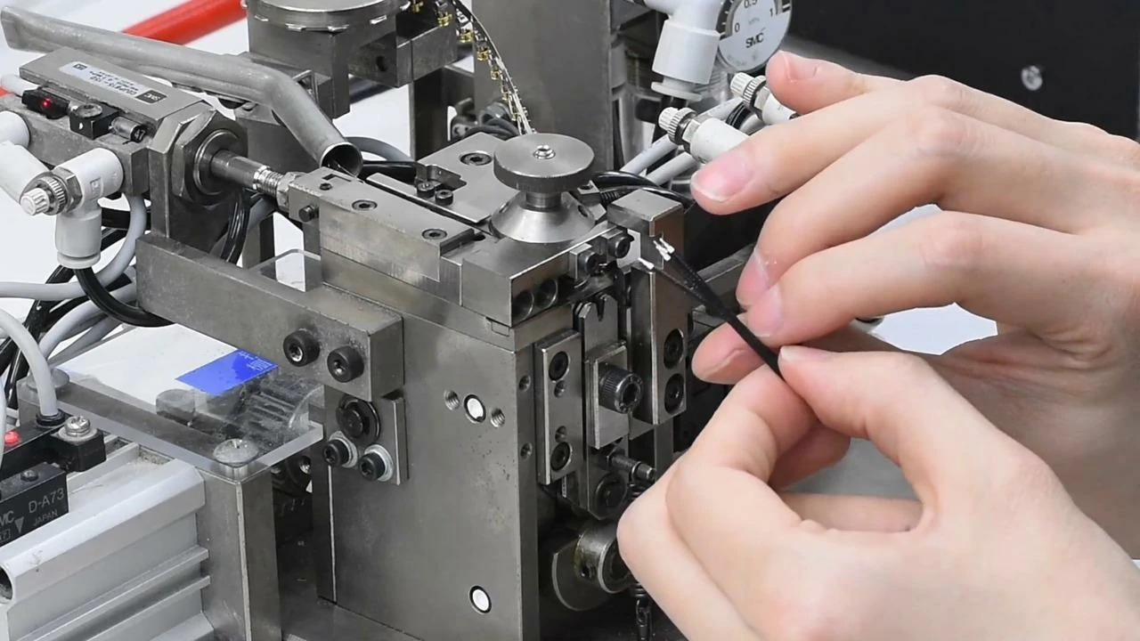
RF cable being positioned in production equipment for connector termination or cable preparation. Controlled processing helps improve dimensional accuracy and assembly consistency.
The cable choice normally depends on where the assembly will be installed.
There is no universal cable that works for every project.
A compact device may need a thin and flexible cable.
A communication system may need lower loss.
A testing system may care more about signal stability.
Flexible Cables for Internal Equipment Connections
FlexibleRF cable assemblies are widely used inside electronic equipment.
A typical example is the connection between:
- Main board and antenna
- Wireless module and external port
- RF module and test connector
In these applications, installation space is often limited.
The cable may need to pass around:
- PCB components
- Metal shielding covers
- Mechanical brackets
Small coaxial cables such as RG316 or RF1.13 are commonly selected because they are easier to install.
However, there is one thing engineers need to consider.
A thinner cable is not always better.
When the cable becomes longer, attenuation gradually becomes more important. A cable that works well at 100 mm may not be suitable for several meters.
For this reason, many RF designers compare cable diameter, flexibility, and loss before making a decision. The RG316 coaxial cable guide provides useful information when selecting compact flexible coaxial solutions.
Semi-Rigid Cables for Fixed RF Paths
Some RF connections do not need flexibility after installation.
For example:
- Inside microwave equipment
- Between RF modules
- Laboratory measurement systems
In these cases, semi-rigid cable assemblies can be considered.
The cable can be shaped during installation and then remain fixed.
This helps maintain a stable routing path.
The main consideration is installation difficulty.
If technicians need to repeatedly adjust the cable position during maintenance, a flexible cable may be more convenient.
Low Loss Assemblies for Long Cable Routes
Cable length changes the selection decision.
A short cable may have very little influence on the system.
A longer cable becomes part of the RF budget.
For example:
An antenna system installed several meters away from the main unit needs to consider how much signal is lost before reaching the receiver.
In this situation, engineers usually pay closer attention to:
- Cable attenuation
- Connector quantity
- Operating frequency
- Required signal margin
A low-loss RF cable assembly may increase the material cost, but it can prevent signal problems later.
The right question is not:
“Which cable has the lowest loss?”
It is:
“Which cable provides enough performance for this application?”
How Should You Match RF Connectors With Cable Assemblies?
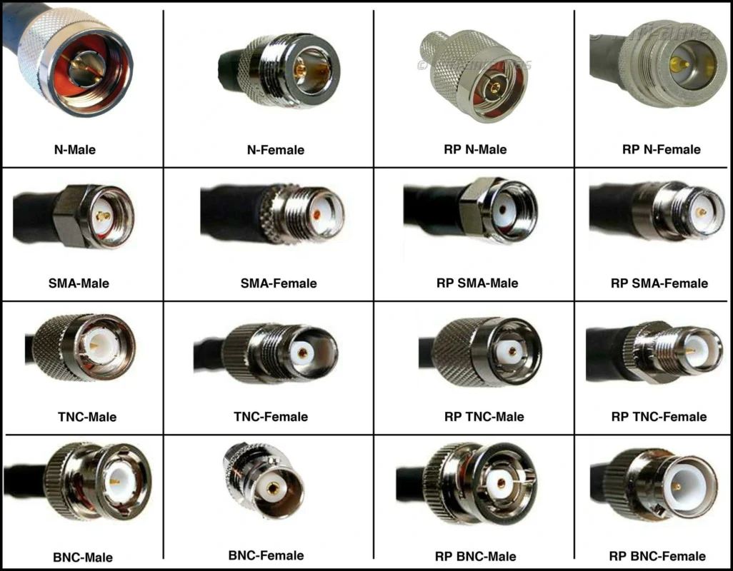
Connector selection usually depends on the equipment interface.
But during cable assembly production, the connector and cable must also match internally.
A connector cannot be selected separately from the cable.
N-Type Cable Assembly Selection.
This gives it advantages when:
- The cable is installed outdoors
- The connector needs stronger mechanical support
- The system handles higher RF power
In these applications, connector selection should be considered together with waterproofing, cable jacket material, and installation method.
BNC and TNC Cable Assembly Selection
BNC and TNC connectors are similar in appearance, but the locking method is different.
BNC uses a bayonet connection.
This makes installation quick.
It is often found on:
- Test instruments
- Measurement equipment
- Signal devices
TNC uses a threaded connection.
The threaded design provides a more stable connection when vibration exists.
When selecting between these connectors, the application environment usually matters more than the connector appearance.
For engineers comparing connector structures, the differences between SMA vs BNC vs N-Type connector comparison can help with interface selection.
What Details Should Be Confirmed Before RF Cable Assembly Production?
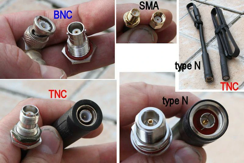
Close-up comparison of BNC, SMA, TNC, and N-Type connectors. The image helps engineers distinguish connector size, locking structure, and interface design when selecting an RF cable assembly.
Many production delays happen because the initial requirement is incomplete.
A supplier may receive:
“Need SMA to SMA cable.”
But several questions remain:
- Which SMA?
- What cable type?
- How long?
- Straight or right angle?
- What frequency?
- Need testing or not?
A complete specification reduces communication time and avoids producing samples that cannot be used.
RF Cable Assembly Specification Template
Before sending an inquiry to an RF supplier, buyers can prepare the following information:
| Item | Example |
| Cable Type | RG316 / RG58 / Low Loss |
| Connector Side A | SMA Male |
| Connector Side B | SMA Female |
| Cable Length | 500 mm |
| Impedance | 50Ω |
| Frequency | DC-6 GHz |
| Cable Direction | Straight / Right Angle |
| Installation Requirement | Indoor / Outdoor |
| Maximum Loss | Required dB value |
| VSWR Requirement | Acceptance limit |
| Test Report | Required / Not Required |
A clear specification helps the supplier recommend a suitable cable instead of only matching the connector name.
How Does Cable Length Affect RF Cable Assembly Performance?
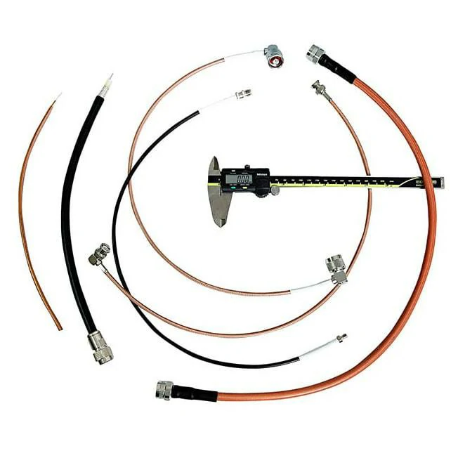
Several RF coaxial cables and completed cable assemblies arranged around a digital caliper. Cable length, connector position, and dimensional tolerance should be confirmed before production.
Cable length is often confirmed at the final stage of an RF project.
The equipment position is fixed, the antenna location is decided, and then someone asks:
“How long should this cable be?”
In many cases, the answer is not only related to installation.
The cable length also changes the electrical performance of the RF path.
A 200 mm cable inside a device and a 5-meter antenna cable may use similar connectors, but they are completely different applications.
The longer cable has more influence on:
- Signal attenuation
- Available power margin
- Return loss
- System sensitivity
This is why cable length should be considered together with cable type and frequency, not as a separate mechanical dimension.
Calculate Cable Loss Before Selecting the Assembly
During RF design, engineers often estimate the expected loss before ordering samples.
The purpose is simple:
To understand whether the selected cable still leaves enough signal margin.
The total loss of an RF cable assembly is usually affected by:
- Cable attenuation
- Cable length
- Connector quantity
- Adapter quantity
- Operating frequency
RF Cable Assembly Loss Budget Formula
Estimated Total Loss = Cable Loss per Meter × Cable Length + Connector Loss + Adapter Loss
Example:
| Item | Value |
| Cable Type | RG316 |
| Frequency | 2.4 GHz |
| Cable Length | 1.5 m |
| Cable Attenuation | 1.46 dB/m |
| Connector Quantity | 2 |
| Connector Loss | 0.2 dB each |
| Adapter Quantity | 1 |
| Adapter Loss | 0.1 dB |
| Estimated Total Loss | 2.69 dB |
This calculation is mainly used during design evaluation.
The actual production cable assembly should still be verified through RF testing because termination quality and connector installation can influence the final result.
Avoid Making the Cable Longer Than Necessary
Longer cable is sometimes easier for installation.
However, extra length also means additional loss.
A common situation in equipment design is:
The engineer leaves extra cable length for assembly convenience.
After testing, the system has less signal margin than expected.
In low-frequency applications, this difference may not be obvious.
At higher frequencies, the effect becomes easier to notice.
A practical approach is:
- Keep the cable route reasonable;
- Avoid unnecessary loops;
- Select a suitable cable diameter;
- Check the loss budget before final production.
For applications requiring better transmission efficiency, engineers often compare different cable structures before selecting the final assembly.
How Should RF Cable Assemblies Be Tested Before Shipment?
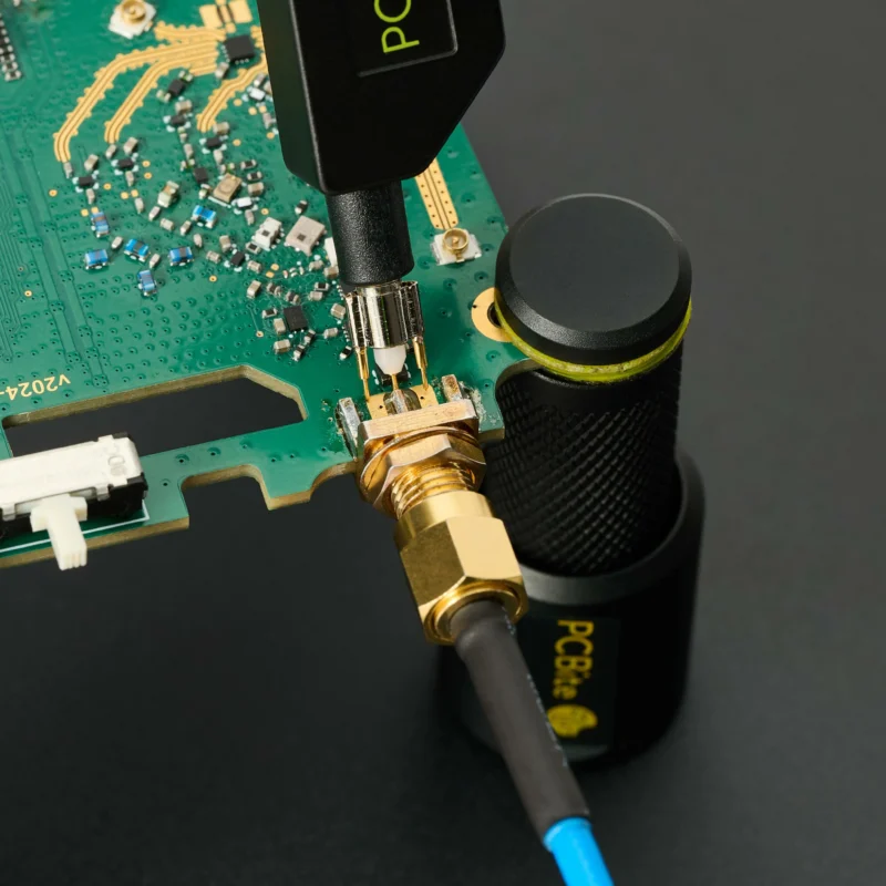
A finished RF cable assembly is more than a combination of cable and connectors.
The assembly process itself affects the final performance.
Two products made with the same materials can show different test results if there are differences in:
- Cable stripping
- Connector installation
- Soldering process
- Crimping pressure
- Assembly consistency
For this reason, RF testing should be performed on the completed product.
Confirm Electrical Performance After Assembly
The required test items depend on the application.
For standard connections, suppliers may perform basic checks:
- Continuity test
- Open/short inspection
For RF-critical applications, additional measurements are usually required:
When Is a Custom RF Cable Assembly Required?
Standard cable assemblies cover many common applications.
However, real equipment designs are often different from standard catalog products.
A customer may need:
- A special connector combination;
- A non-standard cable length;
- A specific bending direction;
- A small installation profile;
- A special environmental requirement.
In these situations, customization becomes necessary.
Consider Customization When Standard Products Cannot Match the Equipment
A typical custom request may look like this:
“One side is SMA, the other side is IPEX. Length is 80 mm. The cable needs to fit inside a small enclosure.”
This requirement includes several details:
- Connector type
- Cable selection
- Mechanical size
- Installation direction
Changing only one item may affect the entire assembly.
For example, replacing the cable with a lower-loss option may increase diameter and make installation impossible.
Provide Mechanical Details Along With RF Requirements
Many RF projects fail during communication because only electrical parameters are provided.
A complete request should include:
- Connector models
- Cable type
- Length
- Frequency range
- Impedance
- Cable routing
- Connector angle
- Working environment
The supplier can then evaluate whether the design is practical before production.
How Can Buyers Evaluate an RF Cable Assembly Supplier?
Choosing an RF cable supplier only by unit price can create problems later.
Cable assemblies involve both material selection and manufacturing control.
A supplier needs to understand:
- RF requirements;
- Mechanical installation;
- Production consistency.
A lower quotation does not always mean a lower total cost if repeated testing or replacement is required.
Check More Than Product Availability
When evaluating an RF cable assembly manufacturer, buyers can review:
- Available cable types;
- Connector processing capability;
- Testing method;
- Sample support;
- Production capacity;
- Quality control process.
For example, a supplier familiar with SMA, N-Type, BNC, TNC, and custom coaxial structures can usually provide better recommendations during the design stage.
RF Cable Assembly Supplier Evaluation Matrix
| Evaluation Area | Questions to Confirm |
| Product Range | Can they provide required cable and connector types? |
| Assembly Capability | Can they handle custom termination? |
| Testing Equipment | Do they support VSWR and loss testing? |
| Engineering Support | Can they review drawings and requirements? |
| Sample Service | Can they provide prototype validation? |
| Quality Control | Are inspection records available? |
| Production Capacity | Can they support repeat orders? |
| Communication Speed | How quickly can technical issues be handled? |
A reliable supplier is not only a manufacturer.
For many RF projects, the supplier also becomes part of the engineering process.
FAQ
What information should I provide when requesting an RF cable assembly?
Provide the connector type, cable model, length, frequency range, impedance, installation requirement, and testing requirement.
Can the same connector use different coaxial cables?
Not always. The connector must match the cable diameter and internal structure.
