
Choose RF Test Cables Before Trusting the Measurement
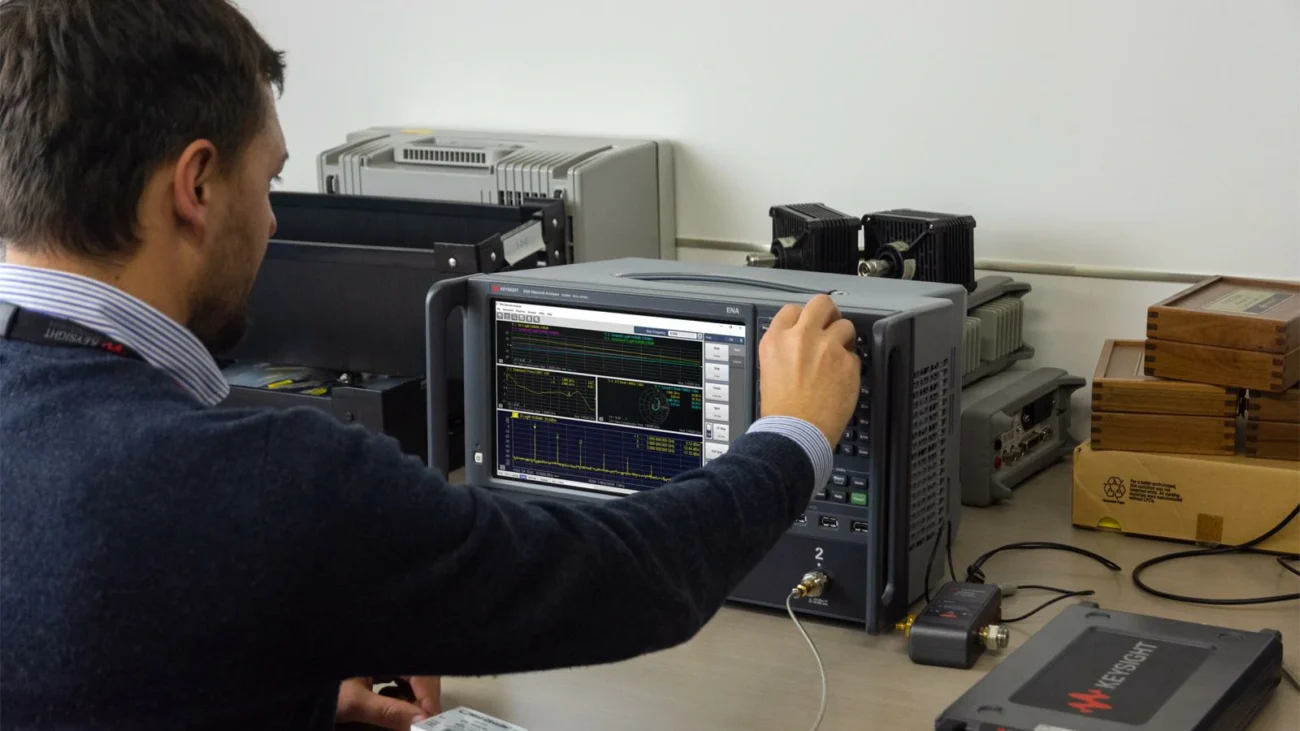
A vector network analyzer can measure extremely small changes in RF performance, but the measurement result is only as reliable as the connection between the instrument and the device under test.
This is why RF test cables are treated differently from ordinary coaxial jumper cables. In a laboratory environment, the cable is not simply used to transfer a signal. It becomes part of the measurement system.
During VNA testing, engineers usually evaluate parameters such as:
- S11 return loss
- S21 insertion loss
- VSWR
- Phase stability
- Amplitude repeatability
A cable that looks electrically normal may still introduce unstable results if the connector interface changes, the cable structure moves after bending, or the insertion loss shifts over repeated measurements.
For engineers working with antennas, wireless modules, and RF components, understanding the relationship between cables and measurement accuracy is as important as selecting the correct VNA settings. Many teams review S11 and S21 measurements before deciding whether a cable is suitable for precision testing.
Explain RF Test Cables Through Real Lab Use
An RF test cable is designed for controlled measurement environments where repeatability matters.
Unlike a common RF extension cable used only for signal connection, a test cable needs to maintain consistent electrical behavior during:
- repeated connector mating
- daily laboratory operation
- fixture replacement
- antenna tuning
- production verification
- calibration procedures
For example, an engineer testing a Wi-Fi antenna module may connect the same cable hundreds of times during development. If the cable characteristics change after repeated movement, the measured antenna performance may appear different even when the antenna itself has not changed.
This creates a common engineering problem:
Is the DUT actually changing, or is the measurement cable affecting the result?
A stable RF test cable helps remove this uncertainty.
The cable becomes a controlled reference between:
- VNA port
- calibration plane
- adapter
- DUT connector
This is especially important when measuring low return loss values or comparing small performance differences between RF designs.
Separate RF Test Cables from Antenna Extension Cables
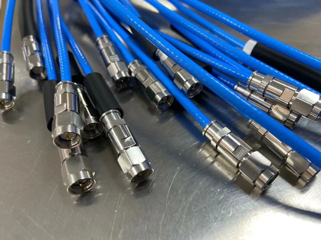
Many purchasing mistakes happen because RF test cables and antenna extension cables look similar.
Both may use:
- SMA connectors
- 50 ohm coaxial cable
- Similar outer appearance
However, their design goals are different.
| Item | Antenna Extension Cable | RF Test Cable |
| Main Purpose | Signal connection | Measurement accuracy |
| Priority | Installation convenience | Repeatability |
| Connector Life | Normal usage | Frequent mating cycles |
| Cable Movement | Limited | Controlled repeated movement |
| Main Concern | Signal transmission | Measurement stability |
| Application | Devices, antennas | VNA, spectrum analyzer, RF test systems |
An antenna cable may work perfectly in a product installation but still be unsuitable for laboratory measurements.
For example, a short SMA cable connecting an antenna inside a device may only need stable operation after installation. A VNA test cable, however, may be connected and disconnected hundreds of times during design verification.
The difference is not only the connector type. It is the mechanical design, manufacturing consistency, and expected measurement environment.
Why Can a Normal SMA Cable Fail as a Test Cable?
Compare SMA Cable Use in Products and Labs
SMA cables are widely used across RF applications because SMA connectors provide a compact threaded connection with good mechanical stability.
However, the same SMA cable specification can have very different performance depending on the application.
A standard SMA cable may be suitable for:
- antenna connections
- GPS modules
- wireless equipment
- short RF links
But laboratory applications often require additional control over:
- insertion loss consistency
- phase change after bending
- connector repeatability
- cable tolerance
Before selecting a cable, engineers usually check the complete cable construction rather than only the connector name.
Factors include:
- coaxial cable type
- dielectric material
- shielding structure
- connector assembly quality
- operating frequency
For more details about SMA cable construction and selection factors, engineers can refer to the SMA cable structure and selection guide when comparing different SMA cable assemblies.
Identify Failure Modes During Repeated Bending
Cable movement is one of the most overlooked issues in RF testing.
A cable may pass initial inspection but gradually change after repeated bending.
Common failure sources include:
Connector stress
Repeated tightening and removal may affect:
- center contact alignment
- mechanical tolerance
- thread condition
Cable deformation
Bending can influence:
- dielectric position
- conductor spacing
- shielding consistency
Measurement drift
The result may appear as:
- changing S11 curve
- unstable insertion loss
- phase variation
For high-frequency applications, even small physical changes can become visible in VNA measurements.
This is why some laboratories use phase-stable cables for applications requiring repeated movement.
Decide When a Standard SMA Cable Is Still Enough
Not every application requires a high-end RF test cable.
A standard SMA cable may still be acceptable when:
- frequency requirements are moderate
- measurements are simple
- cable movement is limited
- repeatability requirements are low
Examples:
- checking basic signal connection
- prototype demonstration
- low-frequency RF validation
However, when the cable becomes part of a measurement process, the requirements change.
Applications that usually justify dedicated RF test cables include:
- VNA characterization
- antenna matching
- production RF inspection
- wireless module validation
- research laboratory testing
The selection should be based on measurement risk rather than only cable price.
Understand Cable Material Before Selecting Test Cables
The coaxial cable inside the assembly strongly affects RF performance.
Different cable types provide different balances between:
- flexibility
- attenuation
- size
- mechanical strength
- frequency capability
For example, engineers often compare RG cable families when selecting RF assemblies for different frequency ranges.
Understanding differences between cable structures helps avoid choosing a cable that works electrically but fails mechanically during testing.
TEJTE provides additional information about cable construction and application differences in the RG cable types guide.
Use This Test-Cable Selection Matrix Before Ordering
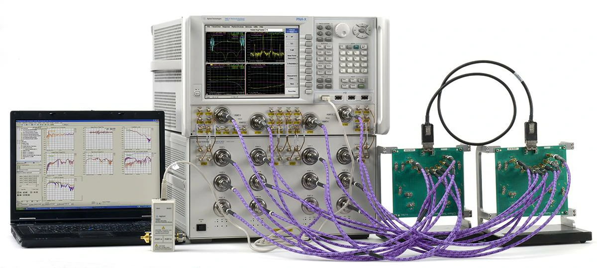
Laboratory VNA measurement system connected to multiple test boards through RF test cables. This type of setup is used for multiport S-parameter, insertion loss, return loss, and RF component verification.
A common mistake in RF testing is choosing a cable only by connector type.
A cable with SMA connectors at both ends may look suitable for a VNA setup, but the measurement result depends on much more than the connector interface.
The cable becomes part of the measurement path.
Its electrical and mechanical characteristics can influence:
- insertion loss
- return loss
- phase repeatability
- measurement consistency after repeated use
A short cable used for occasional testing may have very different requirements compared with a cable connected to a production fixture every day.
Before selecting an RF test cable, the actual working condition needs to be defined first.
Questions normally considered during selection include:
- What frequency range will be tested?
- How many connection cycles are expected?
- Will the cable remain fixed or move frequently?
- Is phase variation acceptable?
- How much insertion loss can the system tolerate?
Match the Cable Specification With the Measurement Scenario
Different RF testing environments create different cable requirements.
A development engineer working on antenna matching may care more about phase stability and repeatability.
A production engineer checking hundreds of finished modules may focus more on connector durability and consistent results between units.
A field technician repairing communication equipment may need a cable that survives bending and transportation.
The following matrix helps separate these situations.
RF Test Cable Selection Matrix
| Test Scenario | Typical Frequency | Connector Requirement | Cable Requirement | Main Concern | Recommended Specification |
| VNA laboratory measurement | DC to GHz range | SMA / N / 3.5mm | Stable coaxial assembly | Repeatable S-parameter results | Low-loss RF test cable |
| Antenna tuning | 2.4GHz / 5GHz / 6GHz | SMA / IPEX / N | Flexible but stable cable | Accurate matching result | Phase-controlled assembly |
| Production RF inspection | Application dependent | SMA / MMCX / N | High durability cable | Same result after many cycles | Reinforced test cable |
| Wireless module verification | Sub-6GHz | SMA / U.FL | Low-loss flexible cable | Avoid measurement deviation | Controlled impedance cable |
| Outdoor troubleshooting | Wide frequency range | N / TNC / SMA | Rugged jacket cable | Mechanical reliability | Outdoor RF assembly |
| Fixture-based testing | Application dependent | Custom interface | Fixed-length cable | Repeatability between stations | Standardized cable set |
Why Cable Selection Cannot Be Based Only on Frequency
Frequency rating is usually the first specification buyers check.
However, two cables with the same frequency range may behave differently during actual testing.
A cable used near the upper frequency limit may show:
- increased insertion loss
- larger phase variation
- more sensitivity to bending
A cable used far below its maximum frequency may provide additional performance margin.
For laboratory applications, the practical working frequency is often more meaningful than the maximum frequency written on a datasheet.
For instance, a cable rated to 6 GHz may perform differently when used continuously at 5.8 GHz compared with occasional measurements at 2.4 GHz.
The surrounding conditions matter:
- cable length
- connector quality
- installation method
- bending radius
- mating frequency
When Should You Use a Phase Stable Cable?
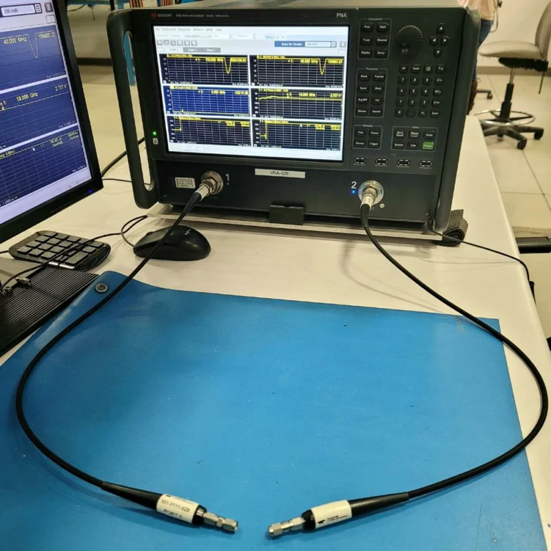
Understand Phase Stable Cable From a Testing Perspective
A phase stable cable is designed for situations where cable movement cannot be completely avoided.
In ordinary RF connections, the main requirement is usually signal transmission.
During measurement work, the concern changes.
The question becomes:
Will the cable produce the same result after it moves?
A small mechanical change inside a coaxial cable can influence electrical length.
That change may become visible when measuring:
- antenna phase response
- filter characteristics
- amplifier behavior
- multi-port RF systems
A phase stable cable reduces these variations by controlling the cable structure and mechanical characteristics.
Identify Applications That Actually Need Phase Stability
Not every VNA test requires a phase stable cable.
A standard RF test cable may be sufficient when:
- the cable position never changes
- measurements are simple
- only signal presence is checked
- accuracy requirements are moderate
Phase stable cables become more valuable in situations such as:
Antenna development
During antenna tuning, engineers may compare several design versions.
If the test cable changes between measurements, the antenna comparison becomes less reliable.
Automated test fixtures
Production fixtures often repeat the same measurement thousands of times.
Cable movement and mechanical stress become important factors.
Portable RF measurement
Field testing frequently involves repositioning equipment and cables.
A cable with better phase stability helps maintain measurement consistency.
How Much Loss Should RF Test Cables Add?
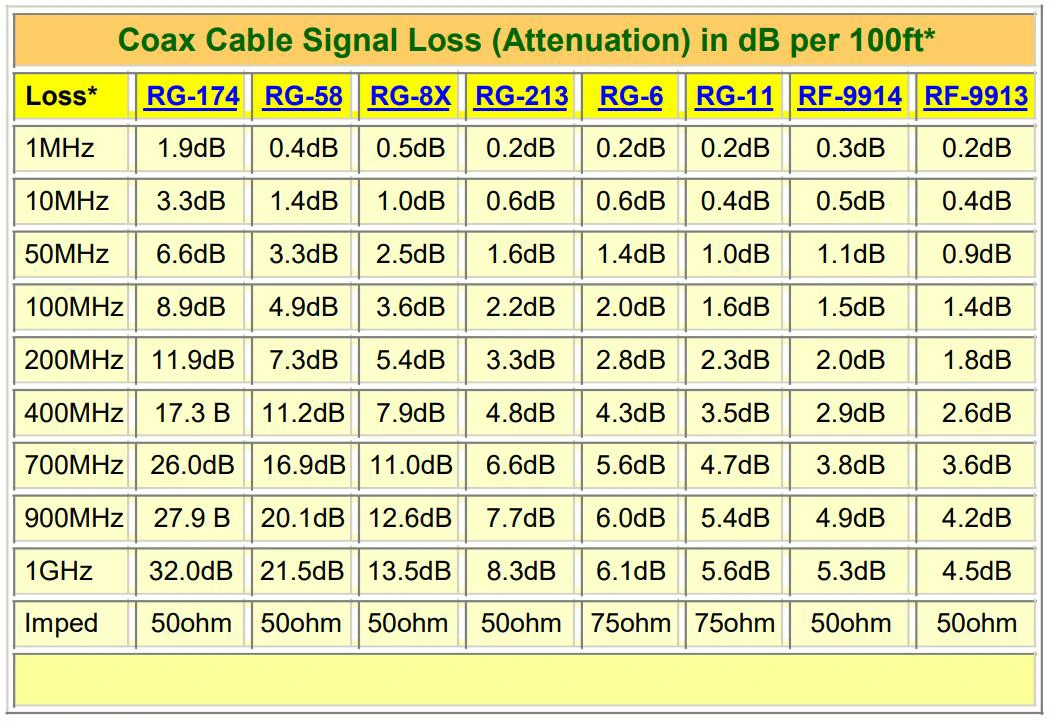
Coaxial cable signal loss chart comparing RG174, RG58, RG8X, RG213, RG6, RG11, RF9914, and RF9913 cables. The chart illustrates how cable type and frequency influence attenuation.
Evaluate Cable Loss Together With Length
Every RF cable introduces attenuation.
The final impact depends on:
- cable type
- conductor material
- dielectric structure
- operating frequency
- cable length
A short cable may introduce very little loss, while the same cable type over several meters can significantly affect measurement margin.
This is why RF cable selection normally considers both electrical performance and physical installation requirements.
For laboratory setups, engineers often compare different RG cable types before choosing a suitable cable structure.
Do Not Ignore Connector and Adapter Loss
The cable itself is only one part of the RF path.
A typical measurement path may include:
VNA Port→Adapter→RF Test Cable→Adapter→DUT
Each transition can introduce:
- additional insertion loss
- impedance discontinuity
- reflection
This becomes more noticeable at higher frequencies.
A system using multiple adapters may show unexpected loss even when the main cable specification looks acceptable.
Test Cable Loss Budget Formula
When estimating the total measurement path loss, use:
Total Test Path Loss=Cable Loss × Cable Length+Connector Pair Loss × Number of Connector Pairs+Adapter Loss × Number of Adapters
Calculation Reference Table
| Parameter | Description |
| Frequency | Actual test frequency |
| Cable Type | RG316 / RG142 / Low-loss cable |
| Cable Length | Physical cable length |
| Cable Loss | Attenuation per meter |
| Connector Quantity | Number of interfaces |
| Adapter Quantity | Additional transitions |
| Estimated Total Loss | Complete signal path loss |
| Evaluation Result | Accept / Replace / Reconsider |
How Can RF Test Cables Influence S11 Results?
Check the Cable Before Assuming the DUT Is Wrong
When an antenna measurement suddenly changes, the first assumption is often that the antenna design has a problem.
However, the cable connection should also be checked.
Possible cable-related causes include:
- damaged connector contact
- loose SMA interface
- worn mating surface
- cable movement during measurement
These issues may create:
- unstable return loss curve
- shifted resonance point
- unexpected ripple
A quick comparison with a known-good cable can often identify whether the problem comes from the DUT or the measurement chain.
Keep Cable Position Consistent During Testing
Mechanical position matters more than many users expect.
During repeated VNA measurements:
- avoid changing cable routing
- avoid sharp bending near connectors
- avoid pulling the cable during connection
A repeatable physical setup usually produces more reliable measurement data.
For engineers working with RF measurement parameters, understanding S11 and S21 behavior helps separate cable effects from actual device performance.
How Can RF Test Cables Influence S21 Results?
Separate Cable Loss From Device Loss
When measuring insertion loss, the result includes everything between the VNA ports.
A higher-than-expected S21 value may come from:
- cable aging
- connector damage
- adapter mismatch
- incorrect calibration
Replacing the DUT immediately may not solve the problem.
The measurement path itself needs verification.
Maintain the Same Cable Setup for Comparison Tests
For comparative testing, consistency is often more valuable than absolute numbers.
A reliable comparison normally keeps:
- same cable model
- same cable length
- same connectors
- same calibration method
This reduces unnecessary variables during product evaluation.
Remove Test Cables That Become Unstable Variables
RF test cables do not always fail completely.
Some cables continue passing signals but gradually become unreliable for precision measurement.
Typical warning signs:
- measurement curve changes after bending
- connector feels loose
- insertion loss increases
- repeat results are inconsistent
Once a cable starts affecting measurement repeatability, replacing it is usually more efficient than repeatedly investigating uncertain test results.
RF Test Cables Guide for VNA Measurements
How Do 6 GHz Wi-Fi and VNA Labs Change Cable Requirements?
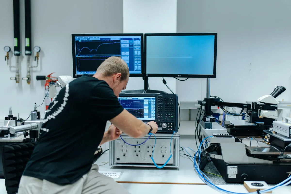
When RF systems move toward higher frequencies, the test cable becomes harder to ignore.
A cable that works well for a basic RF connection may create unexpected variation when it is used as part of a measurement setup.
This situation is common in Wi-Fi 6E, Wi-Fi 7, and other wireless hardware testing.
At 6 GHz, small differences caused by:
- cable construction
- connector quality
- bending condition
- adapter transition
can appear directly on measurement curves.
During early prototype testing, these differences may not attract attention because engineers are still changing the design frequently. However, once the design enters comparison testing or production verification, measurement repeatability becomes much more important.
A stable RF test cable helps separate two different issues:
- Is the product performance changing?
- Or is the measurement path changing?
Look Beyond the Frequency Number on the Datasheet
Frequency range is usually the first item checked when buying RF test cables.
However, the highest supported frequency does not always represent the best working condition.
For instance, a cable marked DC–6 GHz may technically support a 6 GHz system. But if the application requires continuous measurements close to that limit, other factors become important:
- insertion loss consistency
- connector repeatability
- phase change after movement
- long-term mechanical stability
A laboratory cable used once during development and a cable used every day on a production fixture do not face the same requirements.
The specification needs to match the working environment.
Manage Cable Routing in Small RF Fixtures
Compact wireless products often create another challenge.
There may be very limited space around:
- antenna connectors
- test pads
- RF shields
- fixture structures
A cable that is forced into an unsuitable position can transfer mechanical stress to the connector.
Over time, this may lead to:
- unstable contact
- changing measurement curves
- premature connector damage
For this reason, cable selection is not only an electrical decision.
The physical installation method matters as well.
How Should Buyers Write RF Test Cable Specifications?
A request such as:
“Need SMA cable for VNA test”
is usually not enough for accurate quotation.
From a supplier perspective, several different products could match that description:
- flexible SMA jumper
- low-loss SMA cable assembly
- phase stable test cable
- high-cycle RF measurement cable
They may look similar but serve different purposes.
A more complete specification allows both sides to evaluate the same product.
Include the Details That Affect Measurement Results
A useful RF test cable specification normally describes:
- connector interface
- cable type
- length
- frequency range
- impedance
- loss requirement
- application environment
For example:
A 20 cm SMA cable used on a VNA calibration fixture has different requirements from a 2 m SMA cable used for antenna installation.
The connector may be the same, but the expected performance is different.
Ask for Test Data When Measurement Accuracy Matters
A datasheet provides general product capability.
For measurement cables, actual test results are often more valuable.
A buyer may request:
- insertion loss curve
- return loss curve
- VSWR data
- frequency sweep
- test conditions
This information helps confirm whether the cable matches the intended application.
Especially in RF measurement, two cables with identical labels can still produce different results because assembly quality and manufacturing consistency affect the final performance.
RF Test Cable Purchase Specification Sheet
| Specification Item | What to Confirm |
| Application | VNA measurement / antenna test / production inspection |
| Quantity | Required purchasing quantity |
| Connector A | SMA / N / TNC / 3.5mm / other |
| Connector B | Matching interface |
| Cable Structure | RG316 / RG142 / low-loss / phase stable |
| Cable Length | Required assembly length |
| Frequency Range | Working frequency range |
| Impedance | Usually 50 ohm |
| Insertion Loss | Maximum acceptable loss |
| Return Loss / VSWR | Reflection requirement |
| Phase Stability | Required for movement-sensitive testing |
| Flex Requirement | Expected bending condition |
| Jacket Material | Protection requirement |
| Test Report | Required measurement record |
| Labeling | Cable identification method |
How Should RF Test Cables Be Verified After Receiving Them?
Receiving a cable does not mean the evaluation process is finished.
For normal jumper cables, checking appearance and continuity may be enough.
For RF test cables, a baseline measurement provides much more value.
The first measurement becomes a reference for future comparison.
If a cable produces different results several months later, the original record helps identify whether the cable has changed.
Establish a Baseline Before Daily Testing
A basic incoming check may include:
- connector inspection
- cable length confirmation
- continuity check
- VNA sweep
- insertion loss measurement
- return loss measurement
The purpose is not only to accept or reject the cable.
It also creates a performance record.
In many laboratories, the biggest problem is not a completely failed cable.
The difficult cases are cables that still work but slowly introduce uncertainty into measurements.
Incoming RF Test Cable Acceptance Checklist
| Check Item | Verification Method |
| Appearance | Check connector and cable condition |
| Connector Fit | Confirm mating quality |
| Cable Length | Measure actual length |
| Cable Routing | Check bending condition |
| Continuity | Electrical connection test |
| S11 Measurement | Verify return loss behavior |
| S21 Measurement | Verify insertion loss behavior |
| Frequency Sweep | Confirm operating range |
| Reference Data | Save baseline measurement |
| Identification Label | Record cable information |
| Final Result | Pass / Fail |
| Inspector Record | Date and operator |
How Can RF Test Cables Be Managed During Long-Term Use?
Treat Test Cables as Measurement Equipment
A common problem in RF laboratories is that cables are treated like ordinary accessories.
A damaged power cable is usually replaced immediately.
An RF cable may continue passing signals even when its measurement performance has already changed.
This difference makes cable management important.
A simple management method includes:
- assigning cable identification numbers
- recording initial measurement data
- controlling usage conditions
- removing unstable cables from testing stations
Pay Attention to Mechanical Damage
Most RF test cable problems do not come from normal signal operation.
They usually appear after repeated handling.
Common causes include:
- excessive connector tightening
- bending close to the connector
- pulling during installation
- storing with sharp loops
A cable can still look normal from the outside while internal performance has changed.
How Do RF Test Cables Support Reliable S11 and S21 Measurements?
A VNA does not measure only the DUT.
It measures the complete path between the ports.
That path includes:
- adapters
- RF test cables
- connectors
- DUT interfaces
Because of this, cable performance directly affects S-parameter results.
When checking abnormal S11 or S21 curves, the cable should be considered part of the troubleshooting process.
Related RF measurement information can be reviewed through TEJTE’s S11 and S21 measurement resources when analyzing cable influence on RF test results.
Internal Link:
S11 and S21 measurement
FAQ
Does a shorter RF test cable always perform better?
Not always.
A shorter cable usually reduces loss, but an overly short cable may create mechanical stress during installation.
The correct length is the shortest practical length that allows proper connection without forcing the assembly.
What information should be provided when ordering RF test cables?
A supplier normally needs:
- connector type
- cable length
- frequency range
- impedance
- application
- loss requirement
- test requirements
Clear information helps avoid receiving a cable that fits mechanically but does not match the measurement purpose.
How often should RF test cables be replaced?
There is no fixed replacement period.
Replacement depends on actual usage conditions.
A cable may need replacement when:
- measurement results become unstable
- connector wear appears
- bending changes results
- insertion loss increases
Performance change is usually a better replacement indicator than operating time.
Final Notes Before Selecting RF Test Cables
Selecting an RF test cable is not only a connector decision.
The cable affects the confidence level of the measurement itself.
For basic connections, a standard SMA cable assembly may be sufficient.
For VNA testing, antenna verification, and production RF inspection, cable stability becomes part of the test system.
A good specification, proper incoming verification, and controlled daily use can reduce measurement uncertainty and improve long-term testing consistency.
