
Insertion Loss
A cable assembly can look perfe
This is som
The connector is installed correctly.
The cable length is correct.
The prod
But when the assembly
The missing factor is usually
Every par
- cable itself
- connector transition
- ad
- as
- frIns
For connector selection, many RF designers first check an RF connector guide to understand the differences between SMA, N, BNC, TNC, and other connector series before confirming the final assembly structure.
Where Does RF Signal Loss Actually Come From?
When an RF signal travels through a connection, it does not simply move from point A to point B without change.
Part of the energy is lost along the way.
The loss may come from several places.
A coaxial cable has conductor loss.
The inner conductor carries the RF current, but the resistance is not zero. At higher frequencies, the current tends to flow closer to the surface of the conductor, which increases effective resistance.
The insulation material inside the cable also affects loss.
Different dielectric materials create different transmission characteristics.
Then there are the connectors.
A connector is not only a mechanical fixing part. Inside the connector, the signal passes through different metal sections, contact points, and dielectric structures.
Any small change in geometry may influence the RF path.
That is why two cable assemblies using the same cable and connector model can sometimes show different insertion loss results.
Why Cannot You Judge RF Loss Only From the Cable Datasheet?
A common purchasing mistake is checking only the cable attenuation value.
For example:
A buyer selects a coaxial cable because the datasheet shows acceptable attenuation at the target frequency.
However, the finished product may contain:
- two connectors
- one adapter
- a right-angle transition
- a bulkhead mounting structure
The cable specification only describes one part.
The actual product is a complete assembly.
The final measured loss includes all sections in the signal route.
A practical RF path may look like:
RF module → connector → coax cable → adapter → antenna
Every connection point needs to be considered.
This is especially important for custom cable assemblies. A few centimeters of cable length difference may not matter at lower frequencies, but at higher frequencies the result can become visible in testing.
How Does Cable Length Change Insertion Loss?
Cable length is one of the easiest factors to estimate.
Longer cable normally means more signal reduction.
However, the relationship is not only about physical distance.
Frequency also changes the result.
A 500 mm cable working at 900 MHz and the same cable working near 6 GHz will not have identical loss behavior.
The higher-frequency signal experiences stronger conductor and dielectric effects.
For short internal connections, flexible cables such as RG316 are often selected because installation space is limited.
For longer connections, engineers usually pay more attention to attenuation.
Before selecting cable length and material, checking RG coaxial cable performance helps avoid choosing a cable that meets mechanical requirements but creates excessive RF loss.
What Should Be Included in an RF Loss Estimate Before Production?
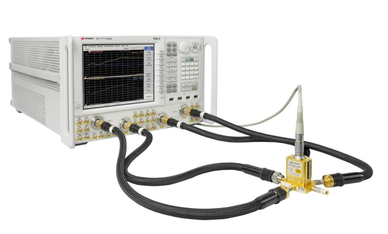
Before making hundreds or thousands of cable assemblies, engineers normally estimate the possible loss range.
A simple calculation method:
Estimated Insertion Loss = Cable Loss + Connector Loss + Adapter Loss
The calculation needs several basic information:
| Item | Example |
| Frequency | 2.4 GHz / 5 GHz / 6 GHz |
| Cable type | RG316 / RG58 / RG142 |
| Cable length | 500 mm / 1 m / 2 m |
| Connector quantity | Two ends / multiple interfaces |
| Adapter quantity | Additional transitions |
| Maximum allowed loss | dB limit |
This estimation does not replace VNA testing.
Its purpose is to identify possible problems before production.
For example:
If the system has only 2 dB available RF margin, adding several adapters may create unnecessary risk even if each individual component looks acceptable.
RF Cable Assembly Loss Review Sheet
| Inspection Point | Confirm Before Production |
| Working frequency | Confirm actual operating band |
| Cable model | Match cable with frequency requirement |
| Cable length | Check installed length, not only drawing length |
| Connector type | Confirm RF rating and impedance |
| Adapter quantity | Reduce unnecessary transitions |
| Loss requirement | Define maximum dB value |
| Test method | Confirm VNA measurement condition |
For RF products, insertion loss is not controlled by one component.
It is the result of the complete transmission path.
A reliable evaluation starts from the finished assembly rather than a single datasheet parameter.
How Do RF Engineers Use Insertion Loss Data During Product Approval?
A supplier’s RF test report often contains a curve that looks simple: frequency on one axis, loss value on the other.
For someone who works with RF products every day, that curve tells much more than a single number.
A cable assembly showing 1.2 dB loss at one frequency does not automatically mean it is suitable for every project.
The same assembly may behave differently when:
- the operating band moves higher,
- the cable length changes,
- another adapter is added,
- the connector interface changes,
- the installation environment becomes different.
During product approval, insertion loss data is normally used together with mechanical drawings, cable specifications, and impedance requirements.
The number itself is only one part of the decision.
How Should You Read an Insertion Loss Formula in Real RF Work?
The common calculation is:
Insertion Loss (dB) = 10 × log10 (Input Power / Output Power)
This formula is straightforward.
The practical question is how the numbers are obtained.
Suppose an RF signal enters a cable assembly with 5 dBm power.
After passing through the assembly, the output drops to 3.8 dBm.
The difference between these two values represents the signal reduction through the path.
The formula helps convert the power change into a value that can be compared across different products.
RF teams often use this calculation when checking:
- prototype results,
- supplier reports,
- simulation assumptions,
- system margin.
However, the calculation alone cannot show where the loss comes from.
A higher-than-expected value may be caused by the cable, but it may also come from the connector transition or test setup.
Why Do Engineers Compare Calculated Loss With VNA Results?
Theoretical values are usually based on ideal conditions.
Production products are not ideal.
A drawing may specify:
- RG316 cable,
- SMA connectors,
- 500 mm length,
- 50 ohm impedance.
The calculation can estimate expected loss.
But the finished assembly still needs measurement.
During VNA testing, the result includes everything:
- actual cable material,
- connector installation,
- solder or crimp quality,
- dimensional tolerance,
- interface contact condition.
That is why a measured result is often different from the value calculated from individual datasheets.
A small difference may be normal.
A large difference usually needs investigation.
How Can You Tell the Difference Between Insertion Loss and Return Loss?
These two parameters are often placed together in RF reports, but they answer different questions.
Insertion loss asks:
How much signal energy is lost while passing through the component?
Return loss asks:
How much signal energy comes back because of impedance mismatch?
A transmission path can have acceptable insertion loss and still have a return loss problem.
For instance:
A cable may allow most of the signal to pass through, but an incorrect connector transition can create reflections.
The equipment receives the signal, but the RF path is no longer operating efficiently.
This situation is common when:
- connector types are mixed,
- adapters are stacked,
- cable preparation is incorrect,
- the mechanical connection is unstable.
For engineers reviewing RF test results, checking return loss and VSWR testing together with insertion loss gives a clearer picture of the assembly condition.
Why Do S11 and S21 Matter When Checking RF Cable Assemblies?
Modern RF testing usually relies on S-parameters.
For cable assemblies, two values appear frequently:
S21 — Transmission
S21 shows how much energy travels from port 1 to port 2.
Insertion loss is normally derived from this transmission measurement.
A lower transmission loss indicates that less signal is absorbed or lost in the path.
S11 — Reflection
S11 shows how much signal returns toward the input port.
It is related to impedance matching.
A connector may have acceptable transmission but poor reflection performance if the interface is not properly matched.
This becomes more noticeable at higher frequencies.
A connector transition that looks acceptable at 900 MHz may show a different response near several GHz.
For this reason, RF engineers normally review the complete frequency sweep instead of checking only one point.
What Factors Make Insertion Loss Increase at Higher Frequencies?
A cable assembly does not have a fixed loss value across all frequencies.
The curve changes.
At higher frequencies, several small effects become easier to see.
The conductor surface carries more of the RF current because of skin effect.
The dielectric material contributes more loss.
Connector dimensions become more critical.
A small change in the RF path can affect impedance continuity.
This is why a product that works well in a low-frequency application may require additional evaluation when moved into a 6 GHz environment.
For applications using compact RF modules, antenna cables, or test fixtures, the frequency range should always be considered together with cable length.
How Is Insertion Loss Measured During Production Testing?
A typical insertion loss measurement uses a vector network analyzer.
The general process is:
- Prepare the test setup.
- Calibrate the VNA.
- Connect the cable assembly.
- Sweep the required frequency range.
- Record the transmission curve.
The measurement result depends on the testing condition.
Important details include:
- calibration method,
- test cable condition,
- connector tightening,
- adapter quality,
- frequency range.
A test report without measurement conditions is difficult to evaluate.
Two suppliers may provide the same value, but the results may not represent the same testing method.
Why Does the Same Connector Require Different Loss Evaluation in Different Applications?
The connector itself is only one part of the system.
A connector used in a laboratory test cable faces different requirements from one installed inside a wireless device.
A short jumper for a measurement setup may focus on:
- repeatability,
- low loss,
- stable phase response.
An outdoor communication cable may focus more on:
- environmental protection,
- mechanical strength,
- long-term stability.
For this reason, selecting a suitable SMA cable assemblies solution requires looking at the complete application rather than only the connector model.
How Do You Decide Whether an RF Cable Assembly Has Acceptable Insertion Loss?
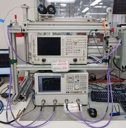
An RF testing station equipped with vector network analyzers and connected test cables. The setup can be used during production inspection to verify cable assembly insertion loss, impedance matching, transmission consistency, and RF performance across the required frequency range.
A question that often appears during RF cable approval is:
“Is this insertion loss acceptable?”
The answer is usually not a fixed number.
A 1.5 dB loss value may be acceptable for one project and rejected for another.
The reason is that the cable assembly is only one part of the whole RF system.
The same cable can be used in different situations:
- inside a wireless device,
- between an antenna and a module,
- in a laboratory test fixture,
- as a communication feeder.
Each application has a different tolerance.
When reviewing an RF assembly, the first step is not asking whether the loss is low.
The better question is:
Does this loss fit the system requirement?
How Do RF Teams Set an Insertion Loss Target Before Production?
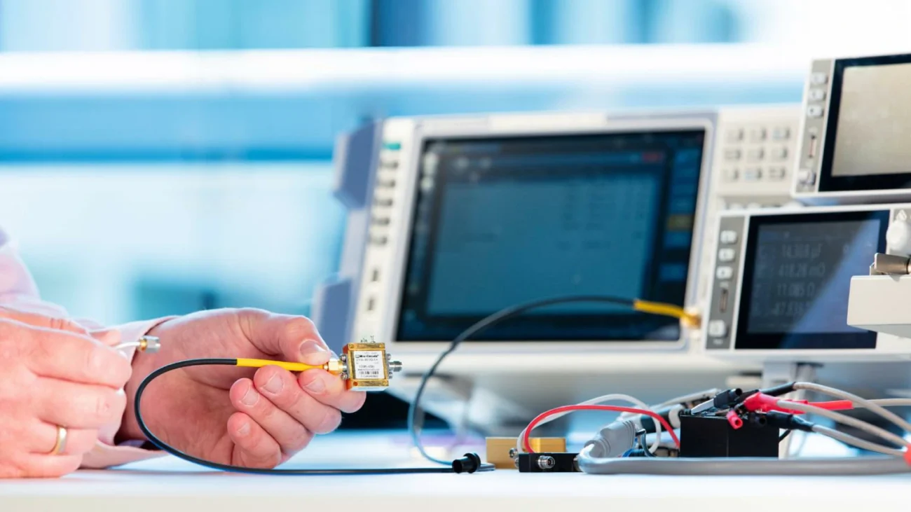
Many problems happen because the loss requirement is discussed too late.
A customer sends a drawing:
- SMA connector on both sides
- 1 meter cable length
- 50 ohm impedance
But the drawing does not mention:
- operating frequency,
- maximum loss,
- test method.
The supplier can build the cable mechanically, but there is no clear RF acceptance standard.
A better specification includes the electrical requirement from the beginning.
For example:
“RG316 SMA cable assembly, 50 ohm, operating at 0–6 GHz, insertion loss ≤ X dB.”
This gives both sides a clear target.
Without a defined limit, different teams may interpret “low loss” differently.
What Factors Should Be Considered in an RF Loss Budget?
In a real RF path, the cable is not the only source of loss.
A typical connection may include:
Module → PCB connector → coax cable → adapter → antenna
The total loss comes from several sections.
A simple estimation:
Total RF Loss = Cable Loss + Connector Loss + Adapter Loss
However, production engineers also need to consider tolerance.
A prototype result may look good.
After thousands of pieces are produced, small differences can appear because of:
- connector batch variation,
- cable material variation,
- assembly consistency,
- operator process.
Leaving some design margin is usually safer than selecting components right at the limit.
RF Cable Assembly Loss Budget Worksheet
| Item | Information to Confirm |
| Frequency Range | Actual working band |
| Cable Model | RG316 / RG58 / RG142 / LMR series |
| Finished Length | Final assembled length |
| Connector Combination | Both ends and interface type |
| Adapter Count | Additional transition points |
| Maximum Loss Requirement | Acceptance limit |
| Test Method | VNA sweep or specified measurement |
This worksheet is useful before quotation and before mass production.
It allows engineering and purchasing teams to discuss the same technical target.
Why Can a Sample Pass but a Production Batch Show Different Loss?
This situation appears frequently in customized RF cable projects.
The sample may be manually checked and carefully assembled.
Mass production introduces more variables.
Possible differences include:
- cable cutting accuracy,
- connector installation position,
- soldering condition,
- crimping force,
- final inspection method.
This does not always mean the product design is wrong.
Sometimes the testing method is different.
Sometimes the acceptance criteria were not clearly defined before production.
For this reason, a good RF supplier normally keeps production records and test conditions consistent between sample approval and batch delivery.
What Should Be Included in an RF Insertion Loss Test Report?
A useful test report should allow another engineer to understand:
What was tested?
How was it tested?
Under what conditions?
A basic report normally contains:
| Report Item | Purpose |
| Product model | Identify tested assembly |
| Cable specification | Confirm actual material |
| Connector type | Verify interface |
| Cable length | Confirm assembly dimension |
| Frequency sweep | Show operating range |
| Insertion loss curve | Check transmission behavior |
| Test equipment | Confirm measurement source |
| Acceptance limit | Compare pass/fail result |
A single statement such as:
“Loss tested OK”
does not provide enough information for technical approval.
How Can Production Teams Reduce Unexpected RF Loss?
In many cases, improving insertion loss does not require changing every component.
Several practical actions are more effective.
Keep the RF path simple
Every additional adapter creates another interface.
If an adapter is not required, removing it can improve reliability.
Match cable selection with frequency
A flexible cable is convenient.
However, a cable chosen only for mechanical reasons may not provide the required RF performance.
Control connector assembly
Connector installation has a direct effect on RF performance.
Small assembly differences can become visible during VNA testing.
Test the finished assembly
Testing individual parts cannot replace testing the completed cable.
The final assembly is what the customer installs.
How Does Higher Frequency Change RF Cable Selection?
A cable that works well at lower frequency may not provide the same result near the upper operating limit.
This is common when moving from:
- sub-GHz applications,
- 2.4 GHz wireless systems,
- 5 GHz equipment,
- 6 GHz RF designs.
At higher frequencies, the RF path becomes more sensitive.
Cable loss increases.
Connector transitions become more noticeable.
Mechanical accuracy becomes more important.
For compact wireless equipment, choosing the correct cable assembly often requires balancing:
- electrical loss,
- flexibility,
- installation space,
- cost.
FAQ
Common Questions Engineers Ask About Insertion LossCan adding one adapter affect RF performance?
Yes.
The effect depends on the adapter quality and operating frequency.
At low frequency, the difference may be small.
At higher frequency, the impact becomes easier to measure.
Should insertion loss be tested after assembly?
Yes.
Testing the finished cable provides the actual performance of the product that will be installed.
Why does the loss value change across frequency?
Because RF transmission characteristics change with frequency.
Cable materials, conductor structure, and connector geometry all influence the final curve.
What should buyers provide when requesting a custom RF cable?
At minimum:
- connector type,
- cable type,
- length,
- impedance,
- frequency range,
- loss requirement.
This information helps suppliers recommend a suitable structure instead of only quoting a mechanical product.
