SMA to BNC Adapter: Direction, Impedance & Lab Mapping
Nov 17,2025
When should you pick an SMA to BNC adapter instead of a short cable?
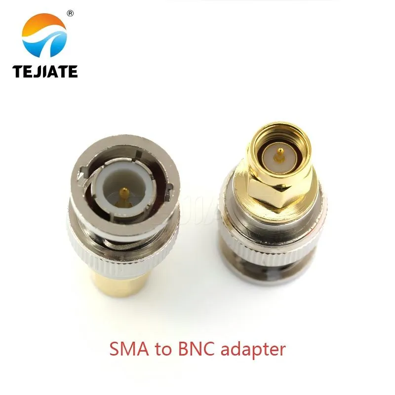
This product photo shows the physical structure of a direct SMA to BNC adapter, suitable for close connections between DUT panels and oscilloscope BNC inputs, adding only 0.05-0.20dB loss at 1GHz per interface while providing stable mechanical connection
There’s a moment on almost every test bench when you wonder whether a simple SMA to BNC adapter will do the job or whether you should reach for a short RG316 cable instead. The choice seems trivial—until it isn’t. In high-frequency setups, too many interfaces become small loss multipliers. At the same time, using a cable where a direct adapter would have worked often introduces unnecessary routing slack and strain on instrument ports.
In practice, engineers treat the decision like a balancing act. If the connection is close—say, a DUT panel only a few centimeters from a scope’s BNC input—a straight BNC-M to SMA-F adapter keeps the path clean. A single interface typically adds only 0.05–0.20 dB at 1 GHz, a figure that aligns with TEJTE’s own data gathered from parts such as the BNC-KF 4-hole flange connector (rated DC–3 GHz, ≤1.2 dB IL). The real advantage is stability: an adapter doesn’t swing or vibrate when you adjust nearby equipment.
When the ports are offset or when two adapters would need to be chained, a short RG316 jumper becomes the safer option. Cables like RG316 or RG316D have predictable loss—typically around 0.45–0.55 dB per 0.5 m at 1 GHz—and eliminate the torque stacking that happens when multiple adapters face each other. We’ve seen situations where chaining two adapters on a spectrum analyzer caused the front-end SMA jack to tilt slightly under load, particularly on older units. A 10–15 cm jumper resolves this elegantly.
Minimize interfaces vs maximize reuse: bench rules of thumb
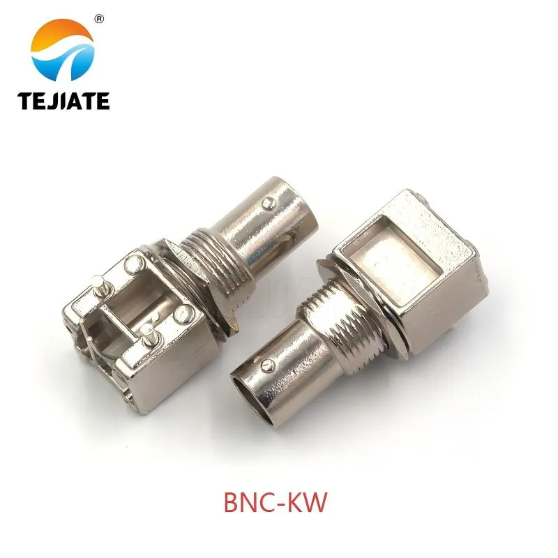
This diagram shows the specific appearance of TEJTE BNC-KW right-angle adapter, made of brass nickel-plated material, alleviating mechanical stress on instrument ports by changing torque direction, especially suitable for use inside equipment bays or near DUT enclosure walls
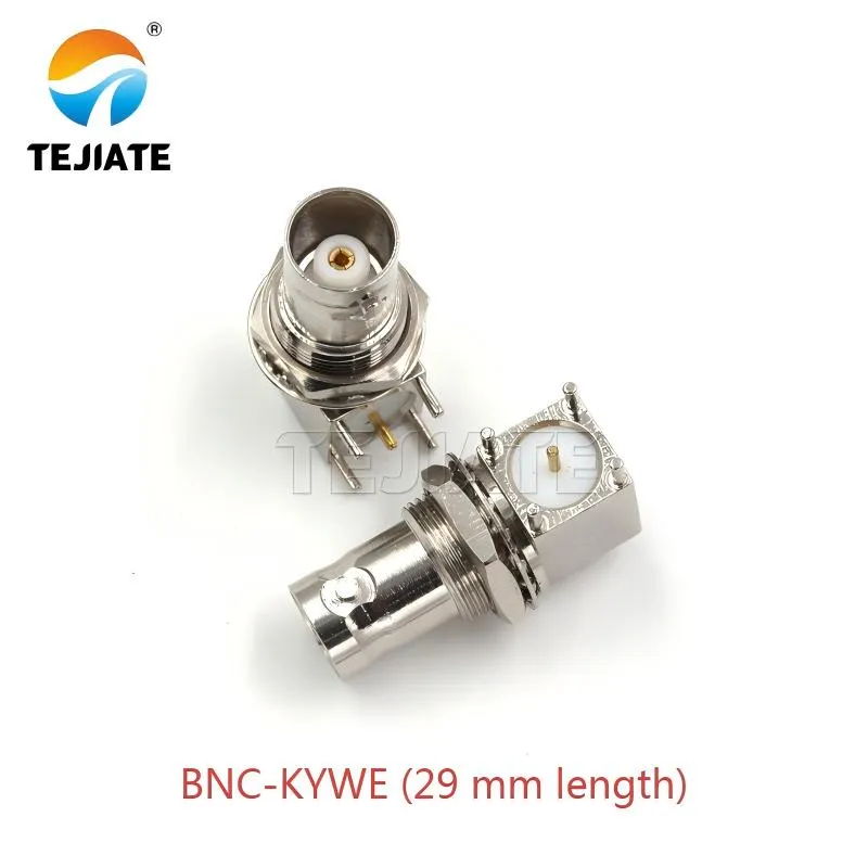
This diagram shows the mechanical characteristics of BNC-KYWE compact adapter, 29mm length suitable for high-density PCB layouts, effectively reducing lever arm effect and providing better repeatability in frequent mating applications
Experienced RF engineers often follow a few informal rules:
- One adapter = acceptable, two = a warning sign.
- If your instrument port is shrouded (common on scopes), avoid stacking adapters; the mechanical clearance gets tight fast.
- Use adapters when the connection is static; use a cable when the connection will be bumped or frequently repositioned.
- If your setup involves TEJTE right-angle BNC models like BNC-KW or compact PCB-mount units like BNC-KYWE (29 mm length), keep in mind they shift the effective lever arm; cables mitigate side load.
These aren’t hard rules, but they explain why top engineers instinctively check the mechanical path before checking the electrical one.
Scope input vs signal source output: where an adapter shines
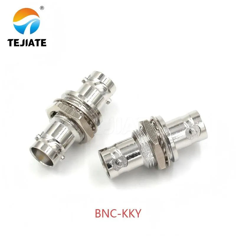
This diagram shows the structural design of BNC-KKY heavy-duty adapter, whose robust construction can withstand torque from hanging cables, protecting instrument front-end SMA-F interfaces from mechanical damage, especially suitable for use on signal generators and analyzers
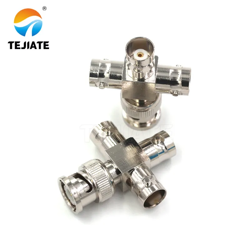
Figure is highlighted in the "Do you need a tee + terminator to loop a signal?" section. It visually presents the key component for solving signal distribution needs. Its feed-through design allows it to provide the correct terminal load for the system while monitoring the signal, making it a fundamental component for building complex test chains.
Oscilloscopes—especially those equipped with traditional BNC-F front ends—are ideal surfaces for a direct adapter. A typical case: a DUT uses an SMA-F bulkhead, and the engineer needs a clean connection to the oscilloscope input. A BNC-M to SMA-M or BNC-M to SMA-F adapter (orientation depending on the DUT pigtail) keeps the connection rigid enough to prevent micro-movements that show up as jitter on sensitive time-domain captures.
Signal generators and analyzers, on the other hand, experience more torque because cables hang off their front panels. Here, using a short cable often protects the instrument better than a bare adapter—even if the electrical path is slightly longer. This is especially true if you’re working with heavier right-angle adapters such as TEJTE’s BNC-KKY or BNC-JKKK (DC–4 GHz, 50 Ω, 1000 V isolation).
How do you map direction & gender without errors?
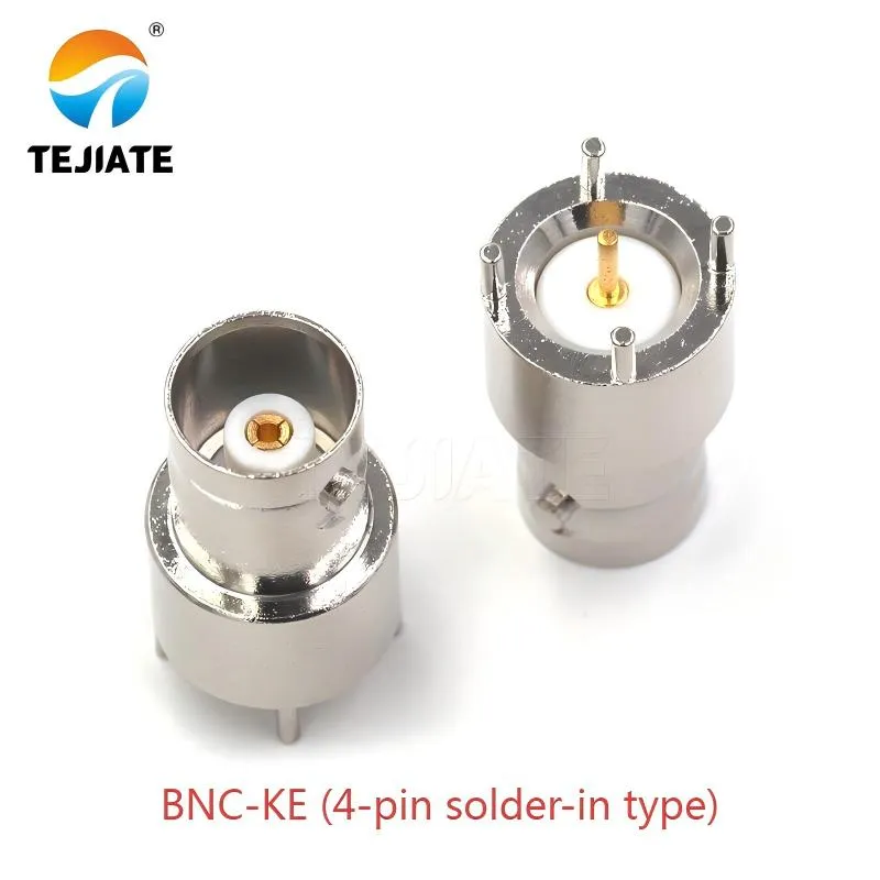
This diagram highlights the installation characteristics of BNC-KE solder-in connector, which presents different gender orientations internally and externally, requiring special attention to signal path direction when designing panels to avoid ordering errors
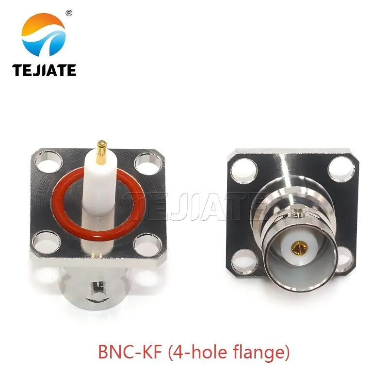
This diagram shows the mechanical design of BNC-KF flange mount connector, 50Ω impedance, operating frequency DC-3GHz, suitable for internal enclosure mounting, presenting different gender characteristics externally than internally, requiring careful signal path planning
Direction mistakes cause more RMAs than performance failures. Engineers think in terms of the signal path (“scope to DUT”), while product listings think in terms of physical gender (“SMA-F to BNC-M”). The two don’t always line up intuitively. Even seasoned techs occasionally order the wrong direction when dealing with panel-mount models like BNC-KE (4-pin solder-in type) or BNC-KF (4-hole flange), because front-view and rear-view orientations get mixed up.
The safest approach is to follow the metal shell, not the pin. SMA and BNC both describe gender by what the outer body accepts, not by where the center pin is. Many beginners assume the pin determines gender; in reality, the shell geometry does.
BNC-M to SMA-F, BNC-M to SMA-M, BNC-F to SMA-M:read the shell, not the pin
A quick sanity check saves hours:
- BNC-M has the rotating bayonet sleeve.
- BNC-F has the fixed body with two bayonet slots.
- SMA-M has an external thread.
- SMA-F has the internal thread.
This matters when you’re designing panels. A TEJTE BNC-KF flange (50 Ω) mounted inside an enclosure presents its opposite gender externally. So a “BNC-F front” might actually require a BNC-M adapter on the outside but behave as BNC-F electrically inside.
The same applies to multi-port splitters such as BNC-JKKK (triple-female cross style)—its symmetrical layout makes gender clear but orientation easy to misinterpret during installation.
Right-angle vs straight adapters in tight panels
Right-angle models like BNC-KW (35 mm long) or BNC-KYWE (29 mm) excel in compact DUT enclosures. Their bending geometry prevents vertical interference but changes mechanical loading. In tight racks or stacked PCBs, right-angle adapters often solve clearance issues—but they rotate the torque vector onto the panel. That’s fine when the internal fixture is solid brass (as on TEJTE BNC-KY series), but risky on thin aluminum panels.
Straight adapters are electrically cleaner; right-angle ones win mechanically when space gets scarce. Engineers usually check where the strain will go before deciding.
Can you mix 50-Ω SMA with 75-Ω BNC safely?
Mixing 50-Ω SMA with 75-Ω BNC is technically possible, but whether it’s acceptable depends entirely on your measurement goal. For many video paths or low-frequency control lines, the mismatch barely registers. But for RF work—anything above a few hundred MHz—the mismatch reflections become noticeable and can distort amplitude or group delay.
A direct 50 to 75 Ω mate yields a reflection coefficient Γ around 0.2, roughly translating to about 14 dB return loss. Engineers working with scopes or spectrum analyzers don’t like to see RL values sink that low. In practice, TEJTE’s 75-Ω BNC connectors (used in broadcast or surveillance applications) show excellent physical quality, but mixing them with SMA gear without a pad still introduces measurable ripple.
Use cases that tolerate 75 Ω(video paths)and when to avoid it
Tolerable:
- CCTV distribution
- Composite video transport
- SD/HD video routers
These applications often run below 100 MHz, and reflections don’t critically impact integrity.
Avoid mixing:
- Synthesizer output verification
- Spectrum analysis above 500 MHz
- Wi-Fi 7 / 5G-Advanced channel evaluation
- High-speed digital edge measurements
In these cases, a 75 to 50 Ω pad is the correct approach.
Matching pad vs direct mate: choose by return-loss target
If your return loss target is ≥20 dB, don’t mate 50 and 75 Ω directly. A precision pad (fixed or switched) restores the chain’s impedance uniformity and protects the instrument port.
TEJTE’s own BNC connectors with high isolation ratings (e.g., BNC-JKKK rated 1000 V, 500 cycles, −45~+125°C) demonstrate that the mechanical quality isn’t the problem—the impedance mismatch is.
Will an adapter change your loss & VSWR noticeably?
Every adapter adds some loss. The key question is whether that loss is small enough to ignore—or whether it quietly erodes your margin. In most bench setups running below a few gigahertz, a single SMA to BNC adapter contributes only a fraction of a decibel. The trouble begins when two or three interfaces stack up or when the test involves tight amplitude or return-loss targets.
Engineers usually start with a simple rule: each interface ≈ 0.05–0.20 dB at 1 GHz, based on common brass-body adapters similar to TEJTE’s BNC-KF or BNC-KYWE series. The loss scales roughly linearly with frequency because the contact geometry concentrates current along the inner conductor.
Return loss follows the same trend. A good adapter sits around 20–22 dB RL at 1 GHz, though practical numbers vary slightly with plating and torque. This is why a single device rarely causes trouble, but chaining two adapters—like putting a BNC-M/F coupler between two SMA-to-BNC adapters—almost always introduces noticeable ripple. On spectrum analyzers, that ripple shows up as a subtle frequency-dependent tilt; on scopes, it can shift high-speed edges just enough to mislead interpretation.
Where things get worse is in 50 to 75 Ω mixed chains. As introduced earlier, the mismatch reflection coefficient (Γ) hits ~0.2, producing ~14 dB RL, which is poor for RF work. A chain that includes a 75-Ω video-grade part, such as a surveillance-style BNC, can degrade VSWR enough to push a measurement from “useful” to “suspect.”
Typical interface penalty and how to budget it(with formulas)
A reliable way to estimate impact is to treat each adapter as a small, predictable penalty:
IL_total ≈ N_interfaces × IL_if
Where IL_if is based on empirical lab data. If you assume 0.1 dB per adapter at 1 GHz, stacking three gives ~0.3 dB. That’s modest, but if your total loss budget is 0.5 dB, you’ve burned more than half before adding cable attenuation.
For mismatch:
Γ = (ZL – Z0) / (ZL + Z0)
ReturnLoss(dB) = –20 log10(|Γ|)
VSWR = (1+|Γ|)/(1–|Γ|)
This becomes relevant when SMA gear talks to 75-Ω BNC. Even high-isolation connectors such as TEJTE’s BNC-JKKK (rated 1000 V, DC–4 GHz) can’t overcome impedance physics.
When two adapters in series become a fail case
A stacked pair—say a right-angle adapter feeding a panel-mount flange—often fails mechanically before it fails electrically. Torque amplifies through the joint. We’ve seen SMA-F ports rotate slightly on older analyzers when loaded with a heavy right-angle BNC adapter such as the TEJTE BNC-KW.
Electrically, two adapters create a tiny resonant cavity. At 3–6 GHz, this can show up as a shallow ripple. If your measurement is part of a Wi-Fi 7 pre-certification chain or a tight SMA vs BNC comparison path, this ripple becomes unacceptable.
When this happens, switch to a short RG316 jumper or re-route with a single straight adapter positioned closer to the DUT.
What adapter should a scope or spectrum analyzer use?
Oscilloscopes and spectrum analyzers may both accept BNC or SMA, but the mechanical and electrical considerations differ. Choosing the wrong direction or geometry can shorten port life or distort traces. Since most scopes still use BNC-F inputs, the common adapter is BNC-M to SMA-M or BNC-M to SMA-F, depending on the DUT’s pigtail. That said, the correct choice depends on clearance, torque, and whether the instrument’s BNC is shrouded.
Spectrum analyzers typically expose SMA-F on the front. These ports are sensitive, especially at the female thread. A bulky adapter—like a right-angle BNC-KYWE—can overload the connector. A lightweight straight adapter is preferred unless routing forces the angle.
To keep the adapter selection consistent with industry practices, many engineers reference connector basics such as those explained in TEJTE’s guide on SMA connector male vs female .
Oscilloscope BNC to SMA mapping checklist(direction, shrouded BNC, strain)
A few checks simplify life:
- Check BNC shroud depth. Some scopes recess the BNC port by 2–3 mm; oversized adapters may not fully seat.
- Confirm gender by shell, not by pin. A panel-mount like TEJTE’s BNC-KE will expose a different orientation on the inside vs outside.
- Watch strain. Heavy adapters or stiff cables torque the scope’s internal mount.
- Plan routing. If the DUT sits directly above the scope, a right-angle model might be safer mechanically even if IL rises slightly.
If the chain involves a sma to bnc adapter for repeated measurements, torque consistency helps maintain repeatable results. Engineers often “feel” the correct torque more than measure it, but consistency matters.
Spectrum-analyzer SMA to BNC traps(max input level, DC block)
Spectrum analyzers add two traps:
- Maximum input power: Some adapters reduce voltage stand-off slightly due to air-gap differences, which matters when feeding modulated signals.
- DC block considerations: Many BNC-side instruments tolerate DC on input; SMA analyzers often require a block. If your chain includes TEJTE BNC-KF or BNC-KY series connectors feeding into SMA-F ports, check that the upstream source doesn’t leak DC.
A common failure case is feeding a camera-monitor chain (75-Ω BNC) into an analyzer expecting 50 Ω. Always confirm impedance continuity before connecting.
How do you select 50-Ω vs 75-Ω BNC for measurement chains?
Selecting 50-Ω vs 75-Ω BNC is largely a question of the application domain. RF chains must remain at 50 Ω for predictable amplitude and VSWR. Video and surveillance systems traditionally use 75 Ω for cleaner voltage coupling and lower signal distortion at low current.
An engineer may assume that using a 75-Ω BNC in a 50-Ω chain “can’t be that bad,” but the ripple introduced at high frequency says otherwise. Even when the mechanical construction is premium—such as TEJTE’s brass-body models like BNC-KF or BNC-JKKK—the impedance discontinuity creates energy reflection.
When the chain includes both sma vs bnc transitions and a mix of impedance grades, planning becomes even more important. This is where a structured approach helps.
Video vs RF benches; when 50-Ω BNC is mandatory
In RF test benches:
- Use 50-Ω BNC exclusively.
- Maintain uniform impedance from source to analyzer.
- Avoid 75-Ω connectors even if they “fit.”
In video benches (CCTV, SDI-grade distribution):
- Use 75-Ω BNC, particularly when the chain includes long coax runs.
- TEJTE’s 75-Ω variants (surveillance series) provide smoother mechanical mating for repeated patching.
But as soon as an RF instrument enters the loop—scope, analyzer, VNA—you transition to 50 Ω.
Where a 50 to 75 Ω pad belongs in the chain
A proper 50 to 75 Ω pad sits directly at the transition, not somewhere in the middle. Putting it at the wrong location defeats the purpose by allowing reflections to travel along the cable before being attenuated.
Place the pad:
- At the instrument input when feeding 75 Ω into a 50-Ω analyzer
- At the DUT output when stepping from 50 Ω into a 75-Ω distribution chain
- As close as physically possible to the mating connector
- Before any adapters in the line
This ensures the return-loss target—often >20 dB for RF—remains intact.
For engineers needing an overview of BNC construction, details in TEJTE’s BNC coaxial connectors page can help clarify physical layouts before ordering.
Do right-angle adapters degrade accuracy more than straight ones?
Right-angle adapters often carry a reputation for “being worse,” but the truth is more nuanced. Their electrical penalty is small, usually just a slight increase in insertion loss and VSWR. What right-angle bodies really change is mechanical loading, especially when used on instruments with delicate SMA-F threads. In practice, engineers accept a tiny electrical compromise if it prevents much larger mechanical issues.
A typical straight SMA to BNC adapter might add around 0.1 dB at 1 GHz, while a right-angle version introduces perhaps 0.12–0.18 dB, depending on its internal bend geometry. TEJTE’s right-angle BNC models, such as BNC-KW (35 mm length) or BNC-KYWE (29 mm), are machined from brass and nickel-plated, making them mechanically strong enough to survive tight racks and PCB corners. Still, the bend shifts the torque direction and can push against a panel surface.
Engineers often choose right-angle adapters when working inside equipment bays or near a DUT enclosure wall, where space is tight and straight connectors would collide with nearby components. For example, the footprint of BNC-KW can clear a heat-sink edge where a straight BNC-KF flange wouldn’t. In these situations, the routing benefit outweighs the slight IL penalty.
Small added IL/VSWR vs large strain-relief gains
Right-angle adapters trade a tiny hit in IL/VSWR for a major gain in usability:
- Slightly higher loss due to the bend
- A minor dip in return loss near upper-band edges
- But significantly reduced strain on instrument ports
- Cleaner routing around DUT corners
- Better cable management in vertical racks
In many real benches, avoiding torque damage matters more than chasing a marginally cleaner trace.
Clearance, torque, and repeatability in frequent mating
Frequent mating amplifies mechanical risk. A heavy adapter hanging off an SMA-F analyzer port is asking for misalignment after 100+ connect/disconnect cycles. Right-angle bodies shift the weight closer to the instrument, reducing leverage. This makes them popular in long-term fixtures—even if a straight unit is technically cleaner.
When the mating cycle count climbs (such as 500-cycle durability seen on TEJTE’s BNC-JKKK), repeatability becomes the priority. A right-angle adapter that protects the port can deliver more consistent measurements than a straight adapter that slowly stretches the instrument’s threads.
What recent RF lab updates impact BNC to SMA adapter choices?
Wi-Fi 7 certification & 802.11be finalization: wider channels demand fewer interfaces
5G-Advanced (3GPP Rel-18) frozen: tighter test margins across chains
New VNAs/extenders & high-perf scopes (2025): higher-freq benches favor short paths
Bench upgrades matter too. New scopes and VNA extenders running 6–20 GHz demand extremely short paths. Adapters like TEJTE’s BNC-KF (DC–3 GHz) may remain suitable for mid-band work, but engineers often pivot toward SMA-only chains for wideband sweeps. When BNC to SMA transitions are unavoidable, they choose one high-quality adapter instead of multiple junctions.
For readers needing connector fundamentals, TEJTE’s overview of RF connectors provides grounding on gender, impedance, and frequency behavior
How do you order the exact direction you need with zero RMA risk?
Even seasoned teams sometimes order the wrong sma to bnc adapter direction, especially when dealing with panel-mount parts like BNC-KF or four-pin BNC-KE, where the “front” and “rear” genders differ. The safest method is to stop thinking of gender and start thinking in terms of signal path direction and shell geometry.
Before placing an order, write the chain in plain language:
Scope BNC-M to SMA-F on DUT
or
Analyzer SMA-F to BNC-F on fixture panel
This eliminates ambiguity, because it forces you to specify both the instrument and the DUT orientation. Engineers who adopt this habit see RMA rates drop dramatically.
Write the source-to-load path(e.g., Scope BNC-M to SMA-F on DUT)
A proper notation includes:
- Source port type and gender
- Load port type and gender
- Whether either side is shrouded or recessed
- Whether you need straight or right-angle
- Whether you expect strain relief or rigid coupling
For example, a DUT using TEJTE’s BNC-KE solder-in connector may expose BNC-F externally but BNC-M internally, depending on the mounting direction. Not writing the path leads to mistaken assumptions.
Add panel notes(bulkhead, spacing, RA/straight)and length alternatives
Real panels rarely offer infinite space. A straight adapter might hit a nearby shield can. A right-angle adapter might solve clearance but introduce torque.
Add three extras to your order notes:
- Panel thickness (affects how BNC-KF flanges seat)
- Clearance envelope (e.g., BNC-KW’s 35 mm extension)
- Backup option (short RG316 jumper if alignment is tricky)
Engineers who annotate these details choose more reliable parts and maintain tighter measurement repeatability.
FAQ
1. Which way should the adapter face on a scope input?
Most oscilloscopes present a BNC-F front end. If your DUT exposes SMA-F, the correct sma to bnc adapter depends on what’s on the DUT side. A common pairing is BNC-M to SMA-M when the DUT uses a short coax pigtail, but BNC-M to SMA-F may be required for panel-mounted DUTs that already include an internal pin.
A useful trick is to treat the scope as the load and read the signal chain left to right. Many incorrect orders come from mixing up the orientation on parts like TEJTE’s BNC-KE or BNC-KF flanges, where the internal and external genders differ. When in doubt, read the shell—not the pin—to determine gender.
2. Do I need a 50 to 75-Ω matching pad when mixing SMA and BNC?
If you care about measurement integrity above a few hundred megahertz, yes. A direct 50 to 75 Ω mate produces roughly 14 dB return loss, which is too low for RF-grade amplitude flatness. Even well-built 75-Ω BNC connectors—like those in video or surveillance systems—don’t solve the impedance mismatch.
A matching pad belongs at the exact impedance transition. Place it at the analyzer input if you’re feeding a 75-Ω chain into a 50-Ω instrument. For low-frequency video paths, you might get away without one, but for RF chains, a pad stabilizes VSWR and protects both sides from reflective energy.
3. Is a right-angle BNC to SMA adapter worse than a straight one?
Electrically, the difference is minor—maybe 0.02–0.06 dB additional insertion loss and a slight VSWR bump near the upper edge of the band. Mechanically, however, right-angle parts often improve reliability. By shifting the lever arm closer to the panel or instrument port, they reduce torque on SMA-F threads, which are notoriously sensitive.
Straight adapters like a standard bnc to sma adapter are still the cleanest choice for high-frequency sweeps, but in tight enclosures or DUT stacks, TEJTE’s right-angle units such as BNC-KW or BNC-KYWE often lead to more repeatable results.
4. When is a short RG316 jumper better than a direct adapter?
A short RG316 cable becomes the better option when:
- Two adapters would need to be chained
- Clearance around the instrument is tight
- A heavy right-angle adapter would strain the port
- The DUT sits in an awkward position relative to the instrument
RG316’s loss—typically 0.45–0.55 dB per 0.5 m at 1 GHz—is predictable and often preferable to the mechanical risk of stacking connectors. This is especially true on spectrum analyzers, where SMA-F ports are fragile and expensive to repair.
5. What should I check before ordering an adapter for a spectrum analyzer?
Spectrum analyzers are more sensitive than scopes, so the checklist grows longer:
- Connector gender (SMA-F is typical on analyzers)
- Maximum input power (avoid adapters that reduce breakdown margin)
- Need for DC block (many analyzers require it)
- Mechanical loading (avoid oversized right-angle BNC bodies)
- Impedance continuity (don’t mix in accidental 75-Ω BNC parts)
DUTs with TEJTE connectors such as BNC-KE or BNC-KF can expose different genders inside vs outside the panel. Writing the source-to-load path—e.g., Analyzer SMA-F to BNC-F on fixture—avoids both RMA and lab rework.
6. Can I use a 75-Ω BNC video lead with SMA gear?
Only in specific low-frequency cases. For RF chains, it’s discouraged unless you insert a 75 to 50 Ω pad at the transition. A 75-Ω BNC cable feeding directly into a 50-Ω SMA analyzer typically produces visible ripple in swept measurements and may degrade sensitivity.
Surveillance-style BNC paths are fine for CCTV, SD video, or low-frequency control signals—but RF instruments expect a uniform 50-Ω environment.
7. How do recent Wi-Fi 7 and 5G-Advanced updates change adapter decisions?
Newer standards push bandwidth higher and margins tighter. In Wi-Fi 7 testbeds, one adapter too many can tilt amplitude flatness enough to disturb EVM. For 5G-Advanced Rel-18, even small mismatches matter due to stricter phase-noise expectations.
This trend drives engineers toward single straight adapters, torque-controlled SMA joints, and extremely short jumper lengths. In other words, newer RF standards punish sloppy interface planning. Clean, predictable paths win.
Bonfon Office Building, Longgang District, Shenzhen City, Guangdong Province, China

A China-based OEM/ODM RF communications supplier
Table of Contents
Owning your OEM/ODM/Private Label for Electronic Devices andComponents is now easier than ever.
