SMA to SMA Cable Guide: Length, Loss & Bulkhead Choices
Nov 16,2025
Preface

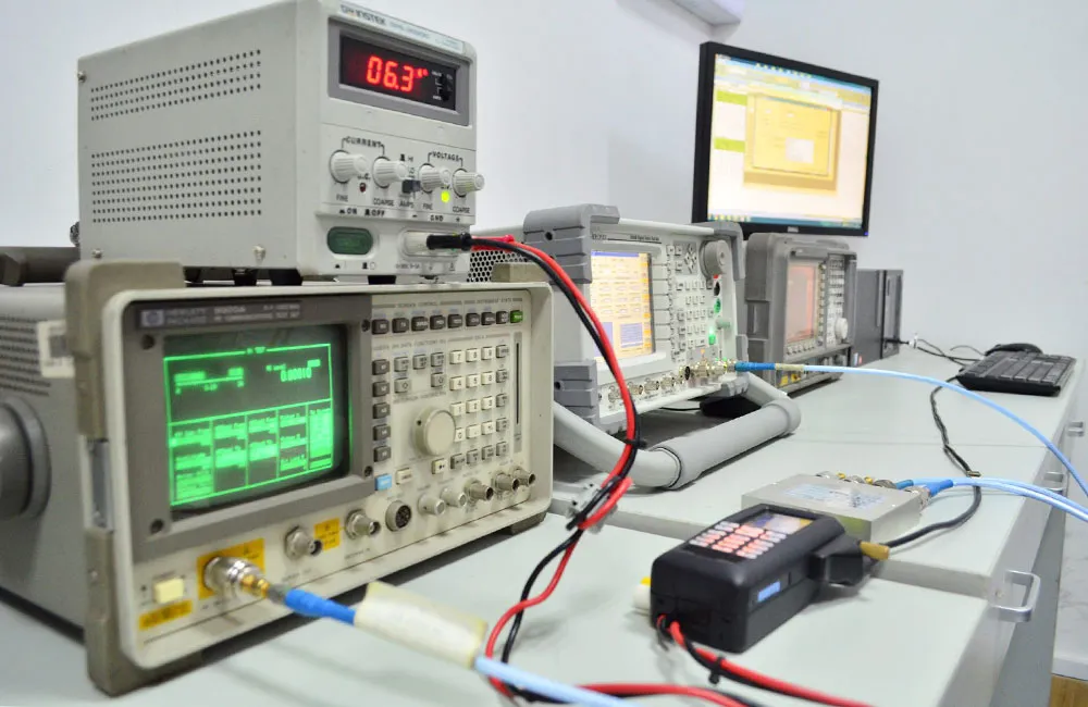
The image anchors the guide’s premise: small choices—jumper length, bend radius, and adapter count—decide signal headroom at 3–6 GHz. The document recommends short, tidy routing and fewer interfaces on lab benches.
If you spend enough time around RF test benches, you eventually learn that a clean setup lives or dies on the small details—how long your jumper is, whether a bend is too tight, whether that “quick fix” adapter added a fraction of a dB too much loss. A sma to sma cable seems trivial, but at higher frequencies—5 GHz Wi-Fi, 3–6 GHz lab test bands, or 5G-NR sub-6 setups—the wrong choice can eat directly into your link budget.
Many engineers choose RG316 cable or RG316D for short bench jumpers because they offer a practical balance of flexibility, thermal tolerance, and low loss. RG316’s attenuation at 2.4 GHz (≈ 1.46 dB/m) and 5 GHz (≈ 2.15 dB/m) is predictable enough that you can size a cable before you even touch your analyzer. Meanwhile, newer Wi-Fi 7 or mmWave extender test rigs push engineers toward cleaner routing, shorter runs, and fewer interfaces.
This guide walks through the practical decision-making process: length selection, loss estimation, male-to-female direction mapping, bulkhead use, and when right-angle ends help more than they hurt. The intent is commercial investigation—helping you choose the sma jumper cable that fits your bench without over-engineering it or introducing surprises. Internal links reference only relevant TEJTE resources, such as SMA connector rules or extension options, kept to a minimum and embedded naturally within context.
How do you size an SMA-to-SMA jumper for your bench?
Engineers typically start with two competing goals: keep the jumper short to reduce loss, yet long enough to avoid sharp bends or strain at the SMA connector. For most benches, the sweet spot is predictable—short sma extension cable segments of 0.1–0.6 m for instrument-to-module routing, and 1–2 m when you need room to move gear.
RG316’s real-world parameters help anchor those choices. With an OD of 2.5 mm, a minimum bend radius of 15 mm, and a propagation velocity of 70%, RG316 jumpers can handle tight bench routing without stressing the dielectric. Engineers who use VNA jumpers daily often keep a few 0.3 m and 0.5 m pieces on hand because they’re long enough to avoid over-looping yet short enough to keep insertion loss down. The same idea applies when using a short sma pigtail from a module to a panel edge.
When longer runs are unavoidable—say you’re routing from a signal generator to a shielded enclosure across the bench—it’s worth examining the frequency you operate at. Once you cross into the 3–6 GHz test range, even a couple of extra feet can add several dB of loss. Still, restraint pays off. A right-angle SMA head oriented correctly on the instrument side often shortens the path enough to drop one loop entirely.
If you’re working with SMA male-to-female chains that involve adapters or gender changers, referencing the SMA male to female cabling rules helps avoid direction errors. Every unnecessary interface adds small but cumulative IL penalties, which matter more as bandwidth widens.
Pick practical presets (0.1–0.6 m; 1–2 m) without over-looping
From experience, preset lengths reduce guesswork. Most engineers keep:
- 0.1–0.3 m for VNA port-1/port-2 patching
- 0.5–0.6 m for oscilloscope or spectrum analyzer runs
- 1–2 m when switching between adjacent racks or enclosures
These lengths align naturally with RG316’s mechanical tolerance. A 0.3 m jumper at 2.4 GHz adds roughly 0.44 dB of loss—usually negligible. A 2 m run, however, can approach 3 dB near 6 GHz, enough to skew lower-power wireless tests.
Balance strain vs loss when space is tight
Lab benches rarely give you the ideal straight path. You often end up fighting between tidy routing and excessive bending. RG316’s 15 mm bend radius helps, but if the cable needs to exit a tight enclosure, a right-angle SMA plug reduces mechanical stress dramatically. The IL of a right-angle SMA is slightly higher than a straight plug, yet the strain relief benefits often outweigh the 0.05–0.1 dB penalty.
If the setup includes a panel mount SMA bulkhead, ensure the panel thickness doesn’t exceed the thread engagement. Poor thread capture leads to loose grounding and intermittent failures—problems harder to diagnose than basic loss.
Estimate RG316 loss before you order

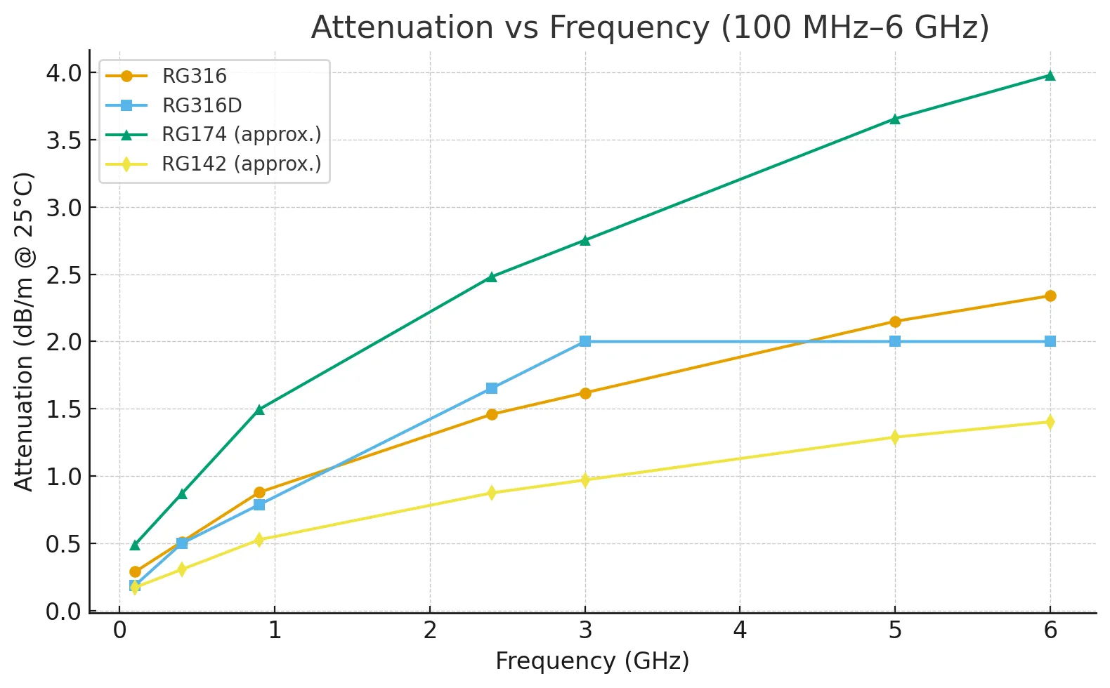
The figure reflects the document’s real-world tables and formulas for RG316 family loss at 2.4–6 GHz, plus typical penalties from straight vs right-angle SMA ends, helping size cables against a loss budget.
Loss estimation is the most overlooked step in selecting an sma to sma cable, but it’s also the easiest to quantify once you have real numbers. Because you supplied authentic attenuation tables for RG316, RG316D, RG174, and RG142, we can build a practical mini-calculator that engineers can use before ordering jumpers.
RG316 attenuation (typical @25 °C, sea level):
- 0.29 dB/m @100 MHz
- 0.88 dB/m @900 MHz
- 1.46 dB/m @2.4 GHz
- 2.15 dB/m @5 GHz
- 2.34 dB/m @6 GHz
RG316D improves screening and drops loss:
- 0.19 dB/m @100 MHz
- 0.50 dB/m @400 MHz
- 2.0 dB/m @3 GHz
RG174 is more flexible but distinctly higher loss (e.g., 147 dB/100 m @2.5 GHz), making it unsuitable for higher-GHz test work. RG142 offers a higher-power, lower-loss alternative for rugged setups, especially when supporting frequencies up to 12.4 GHz.
These authentic values will feed directly into the calculator below.
Length & Loss Mini-Calculator(uses your real parameters)
Inputs:
- Frequency (MHz/GHz)
- Cable type: RG316 / RG316D / RG174 / RG142
- Length (m)
- Connector count (straight vs right-angle)
- Target Z₀ = 50 Ω
- Loss budget (dB)
Outputs:
- Total cable loss (dB)
- Interface penalty (dB)
- Return loss (dB)
- PASS/FAIL
- Recommendation: shorten lead / reduce interfaces
Calculation formulas
CableLoss(dB)
[ CableLoss = \alpha_{dB/m}(f) \times Length + N_{if} \times IL_{per-if} ]
Interface penalty typically:
- Straight SMA: ~0.03–0.05 dB
- Right-angle SMA: ~0.08–0.12 dB
Impedance mismatch & return loss
[ \Gamma = \frac{Z_L – Z_0}{Z_L + Z_0} ]
[ ReturnLoss(dB) = -20\log_{10}|\Gamma| ]
Bend radius check
[ R_{min} \ge k \times OD ]
RG316 recommends k ≈ 10, so roughly 25 mm for safety—well above the bare minimum 15 mm.
Map SMA male to SMA female directions without mistakes

The image echoes the guide’s advice: match by behavior (plug vs jack) and label ends early. This avoids mistakes when chains include bulkheads, gender changers, and right-angle plugs.
Direction mistakes happen more often than most engineers admit, especially during fast bench reconfigurations. SMA male vs SMA female is simple in theory—male has a center pin, female has a socket—but real setups involve bulkheads, adapters, gender changers, and right-angle ends that flip orientations.
A reliable sma male to sma female mapping habit avoids wasted time. One simple trick is to always match by “behavior” rather than appearance: male plugs insert into instrument jacks, while female jacks live on panels, modules, and enclosure walls. This framing reduces confusion when dealing with compact modules where SMA jacks may not visually resemble larger lab instruments.
A second technique is to label the cable ends immediately after unpacking. Many engineers use small heatshrink labels—INST, DUT, PANEL—to avoid accidentally reversing a chain. This is especially valuable when using a sma bulkhead cable through an enclosure where the gender orientation flips across the panel.
Cross-referencing TEJTE’s SMA male to female cabling rules is helpful when the chain involves feedthroughs, RA ends, or multi-connector assemblies.
Estimate length & loss before you buy

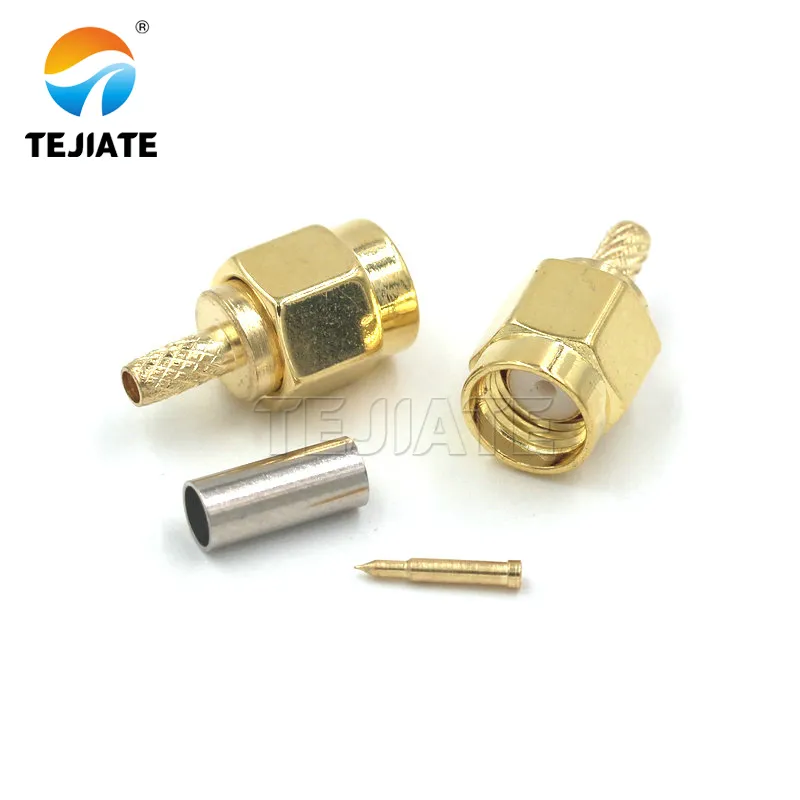
The figure reflects the document’s point that straight ends minimize electrical penalties in short bench chains, making them the default for calibration-grade work.

The image illustrates the guide’s trade-off: a tiny IL penalty versus big mechanical gains—reduced boot bending and longer connector life on crowded benches.
Straight SMA ends maximize bandwidth and minimize IL. They’re the default in VNA calibration kits and analyzer jumpers. Right-angle SMA ends, on the other hand, serve a mechanical purpose. They relieve strain at instrument faces, especially when routing downward or sideways.
The small IL increase of a right-angle head is rarely catastrophic. At 3–6 GHz, expect ~0.05–0.1 dB extra loss per right-angle end. In most bench chains, this is far outweighed by better connector longevity and reduced stress on the mating port.
Labeling habits that prevent field swaps
Do right-angle plugs or bulkheads change accuracy?
Right-angle SMA plugs get a reputation for “ruining” high-frequency measurements, but their real impact is usually much smaller than people fear. The key is understanding when the added insertion loss matters and when the mechanical advantages outweigh the electrical penalty. A right angle sma cable typically adds around 0.05–0.1 dB per connector in the 3–6 GHz range—far from catastrophic in short bench chains. For most sma to sma cable setups under one meter, this difference is easily absorbed in the loss budget, especially if you’re using RG316 or the lower-loss RG316D.
Bulkhead SMA connectors behave similarly. A well-machined bulkhead—with proper nut engagement, clean threads, and consistent 50-ohm geometry—introduces negligible degradation. The biggest mistakes come from mechanical issues: insufficient thread engagement, a misaligned panel hole, or over-torquing that distorts the dielectric. When these are avoided, a bulkhead pass-through behaves almost identically to a standard inline connector.
When a bench setup involves a VNA or signal generator, a bulkhead is often the safer choice because it protects the instrument’s front port from repeated strain. TEJTE’s SMA connector practices outline the same principle: protect the expensive interface; let the jumper take the beating.
Tiny added IL/VSWR vs big gains in strain relief
Engineers who run daily test cycles quickly learn that protecting the mating port is more valuable than chasing fractions of a dB. A right-angle end prevents sharp downward bends, and a bulkhead pass-through keeps the instrument face from absorbing torque. While straight connectors achieve slightly better VSWR, right-angle plugs still maintain respectable performance—typically ≤1.25:1 in good assemblies.
If your frequency range stays under 6 GHz and jumper lengths are short, the mechanical stability benefits outweigh the electrical cost almost every time. The only time to avoid right-angle plugs is when performing ultra-sensitive phase-matched VNA work or calibration-grade measurement tasks.
Keep the 50-Ω path consistent across panels
Where do feedthroughs and bulkhead parts fit a clean chain?

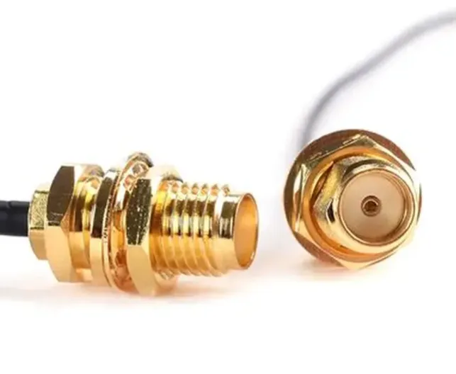
This photo shows a panel-mount SMA feedthrough used to carry a 50-ohm path across the enclosure wall. The locking nut and washer stack secure the connector, while the O-ring provides sealing for outdoor or dusty environments. A short RG316/316D pigtail is typically used inside the box to keep loss and bend stress low.
Feedthroughs become essential when a signal must pass between environments: from a shielded box to the open bench, from an instrumentation rack into an enclosure, or between two separate chambers with differing EMI requirements. A panel-mount SMA feedthrough provides a stable, repeatable interface and acts as a “mechanical firewall” that protects more delicate downstream connectors.
The key is selecting the correct thread length and ensuring proper engagement with the panel thickness. Many SMA bulkheads are designed for panels around 1.5–3.0 mm; exceeding that risks poor engagement or an O-ring that never fully compresses. This often shows up as unreliable grounding or intermittent loss spikes—not the kind of problem you want during wireless performance testing.
One of the cleanest routing methods is to use a feedthrough on the enclosure and then run a short sma extension cable like RG316 or RG316D inside. RG316’s 70% velocity factor, 15 mm minimum bend radius, and high-temperature FEP jacket make it ideal for internal routing around RF modules, power boards, or test fixtures.
If your application requires high shielding effectiveness—such as EMC chambers or noise-sensitive industrial systems—a dual-shield option like RG316D or a heavier cable like RG142 significantly improves stability.
You can reference TEJTE’s page on RF Coaxial Cables if you need broader cable type comparisons, but feedthrough sizing and panel mechanics remain the real deciding factors here.
Panel thickness, washer stack, grounding, sealing basics
Enclosure I/O: keep bends off the connector boot
Which RG316 vs RG174 traits matter without doing product “comparisons”?
Rather than comparing every parameter side-by-side, it’s more useful to look at what actually affects a bench chain: loss per meter, mechanical behavior, and suitability at your operating frequency. The choice between rg316 cable and RG174 often decides whether your sma to sma cable behaves predictably or introduces sudden signal drop-offs.
RG316 offers a solid middle ground. With attenuation of 1.46 dB/m @2.4 GHz and a temperature range up to 150 °C, it handles most lab tasks. Its FEP jacket and silver-plated braid balance flexibility with stability. RG316D adds a second braid, improving shielding and reducing EMI leakage—helpful when routing near switching supplies or multiple RF modules.
RG174, by contrast, trades shielding and high-frequency stability for extreme flexibility. While useful in compact consumer devices, its loss numbers tell the story: 147 dB/100 m @2.5 GHz. On short jumpers this may be tolerable, but over 1–2 m it becomes significant. Mechanical stability also drops due to its PVC jacket and higher bend radius (~28 mm), which can be restrictive in tight enclosures.
RG142 sits at the other extreme—higher power, lower loss, and dual-braided shielding. At 0.42 dB/m @1 GHz and 0.78 dB/m @3 GHz, it beats RG316 on performance but is physically larger and stiffer. Many engineers adopt RG142 when routing through large cabinets or performing tests up to 12.4 GHz where phase stability matters.
Flexibility, shielding, bend radius and when to step up cable class
Short-run heuristics for lab jumpers (≤2 m)
A few rules-of-thumb simplify real-life choices:
- Under 3 GHz and under 1 m to RG316 is ideal
- 3–6 GHz or noisy environments to RG316D
- High-power, long runs, or >6 GHz to RG142
- Extremely tight bends where performance is not critical to RG174
For clean, repeatable lab work on spectrum analyzers, VNAs, or wireless modules, RG316 (or RG316D) consistently delivers the best balance between loss, mechanical life, and connector compatibility.
What recent RF & wireless updates should influence your jumper picks?
Wi-Fi 7 channel widths to fewer interfaces, shorter runs
5G-Advanced lab setups to tighter loss/VSWR budgets
New VNA/mmWave extenders to higher frequency, cleaner terminations
Order exactly what you need, step by step
Choose length, straight/RA, bulkhead/feedthrough, jacket color
A typical ordering workflow is:
- Length
- Under 0.6 m for analyzers, VNAs, local modules
- 1–2 m only when routing across enclosures
- Use your frequency to estimate loss: e.g., 0.5 m RG316 at 5 GHz ≈ 1.08 dB
- Straight or right-angle ends
- Straight for best IL/VSWR
- Right-angle for equipment faces or tight enclosures
- Each RA end adds ~0.05–0.1 dB near 6 GHz
- Bulkhead or feedthrough
- Use when passing through panels or shielded boxes
- Match panel thickness to thread length
- Over-compression of the O-ring risks grounding issues
- Jacket color
- Brown for classic RG316
- Clear or custom colors help identify RF paths in mixed-signal cabinets
If your application must differentiate multiple RF chains, color-coding simplifies troubleshooting.
Custom notes: tolerance, serialization, RoHS/REACH docs
Many labs now require serialized jumpers for repeatable test setups. Adding serialization to each sma pigtail or enclosure jumper ensures traceability during long test campaigns. Some projects also demand RoHS/REACH paperwork for import audits—which is why including documentation in your order note streamlines later compliance checks.
Tolerance notes—such as ±10 mm on cable length—help avoid unexpected slack or tension around the DUT fixture. If you’re ordering a feedthrough + jumper pair, specifying panel thickness in the same note prevents mismatched bulkhead hardware.
For more details on connector selection and SMA behavior, TEJTE’s SMA hardware guide
FAQ
How to build an RP-SMA cable?
How to connect an SMA RF cable to a wireless access point?
What is the maximum distance from antenna to router over SMA?
There’s no universal limit—it depends on frequency and cable loss.
General rule:
- 1–2 m max for RG316 at 2.4/5 GHz
- Longer runs to switch to RG142 or a low-loss coax
- For Wi-Fi 7, try to keep runs <1 m
For example, at 5 GHz, RG316 loses 2.15 dB/m, so a 3 m run costs ~6.45 dB—unacceptable for weaker radios or marginal links.
How to connect coax cable to RP-SMA?
How to attach an RP-SMA connector to cable?
What cable group pairs well with SMA connectors?
What is a good Wi-Fi SMA cable today?
Conclusion
Choosing the right sma to sma cable rarely comes down to one single parameter. It’s usually a mix of length, frequency, connector direction, and the little mechanical details you discover only after spending years around test benches. Short RG316 or RG316D jumpers still cover most day-to-day RF work, and their predictable loss curves make quick estimates easy. If the setup grows more demanding—tight enclosures, higher EMI, or multi-GHz radios—you’ll start to feel the difference between single- and dual-shield cables, or between a clean straight SMA and a right-angle connector that saves your instrument port from long-term strain.
What helps most is treating the assembly as part of the signal chain instead of an afterthought. Engineers who label their jumpers, avoid unnecessary adapters, and keep bends gentle tend to spend less time chasing reflections or unexplained loss. And when panels or chambers get involved, a properly seated sma bulkhead cable with the right washer stack often saves hours of debugging that would otherwise go to grounding issues.
There’s no one “universal” jumper, but there is a right one for each job. Small differences—a 0.3-m cable instead of a 0.6-m one, or a clean feedthrough instead of a loose pass-over—add up quickly, especially at 5–6 GHz. If you pick deliberately and size your jumper with the loss budget in mind, your bench measurements will stay cleaner, your instruments will last longer, and your RF setups will behave far more predictably.
Bonfon Office Building, Longgang District, Shenzhen City, Guangdong Province, China

A China-based OEM/ODM RF communications supplier
Table of Contents
Owning your OEM/ODM/Private Label for Electronic Devices andComponents is now easier than ever.
