SMA to BNC: Cable vs Adapter, Length & Match
Nov 15,2025
Preface
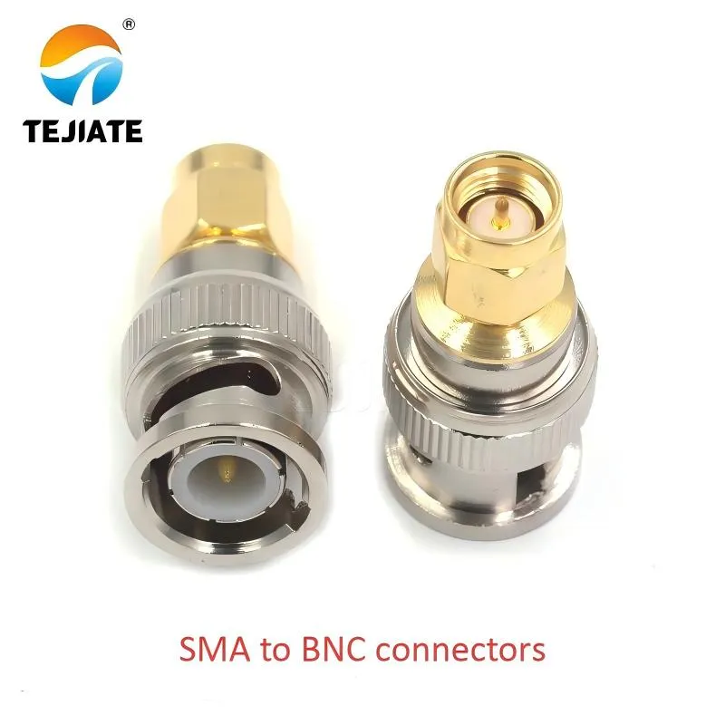
This product photo clearly shows the physical characteristics of SMA to BNC connectors, made of brass gold-plated material with PTFE dielectric, operating frequency up to 12GHz, providing reliable interface conversion solutions for RF testing
In RF benches, one small interface choice often decides whether a clean sine wave stays perfect or drifts into ringing. The link between SMA and BNC connectors—common on oscilloscopes, analyzers, and signal sources—looks trivial but quietly shapes accuracy, repeatability, and mechanical life.
At TEJTE, many engineers use RG316 or RG316D 50-Ω coax to bridge SMA-based modules and BNC-terminated instruments. The goal is always the same: keep loss and mismatch low without turning the bench into a forest of adapters.
This guide walks through when to pick an adapter or a dedicated cable, how to map genders correctly, and how to match impedance between SMA and BNC systems using real-world attenuation and mechanical data.
All RF data and attenuation values in this guide are based on in-house testing from TEJTE’s lab using certified RG316 and RG316D coax assemblies.
When should you use an SMA-to-BNC adapter vs a cable?
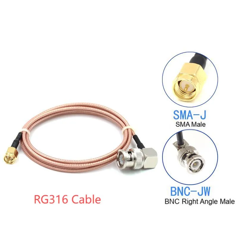
This image complements the text discussing the trade-off between rigid adapters and flexible jumpers (like RG316). The assembly shown demonstrates how to connect SMA and BNC interfaces with a flexible jumper, which absorbs mechanical stress to protect delicate ports but introduces slightly higher insertion loss.
| Option | Typical Insertion Loss | Return Loss (50 Ω) | Mechanical Life | Typical Use |
|---|---|---|---|---|
| SMA to BNC Adapter | ≈ 0.15 – 0.25 dB | > 23 dB | > 500 mating cycles | Quick instrument swap |
| SMA-BNC Cable (RG316) | ≈ 0.3 dB per meter @ 100 MHz (1.65 dB @ 3 GHz) | > 25 dB | > 1,000 flex cycles | Permanent bench link |
Every extra interface adds roughly 0.1 dB of loss and a few tenths of a dB in VSWR ripple. On a low-GHz chain that may sound small, but at 6 GHz the extra mismatch can steal several dB of dynamic range from a spectrum analyzer.
For that reason, use adapters only when swapping gear (for example, an SMA generator into a BNC scope input). Use pre-built RG316 jumpers when the connection will live on your setup for weeks or is part of an automated test fixture.
Bench example:
A 0.5 m RG316 SMA-M to BNC-M cable contributes roughly 0.9 dB at 1 GHz and ~1.65 dB at 3 GHz. Replacing it with two adapters and a generic BNC cable can push loss beyond 2 dB—noticeable on wide-band measurements.
Material insight: TEJTE’s SMA connectors use brass + gold plating, PTFE dielectric, and maintain VSWR ≤ 1.2 up to 18 GHz, which fits most lab chains.
Lab scenarios
- Oscilloscope input: Prefer a short SMA-to-BNC cable (≤ 0.6 m) to minimize strain on the scope front end.
- Spectrum analyzer input: Use a dedicated 50-Ω jumper rated to 6 GHz or higher; avoid adapters that might loosen under torque.
- RF source output: Adapters work for quick tasks, but keep the SMA connector torqued to ≈ 0.45 N·m to protect the female center contact.
Pro Tip: Reusing old BNC cables through adapters seems cheap but can increase reflection ripple by > 2 dB across a GHz span.
For a deeper background on SMA connector geometry and torque, see the SMA Connector Guide.
Map SMA/BNC genders correctly the first time
| SMA Type | Mating Side | Typical Marking | BNC Mate Target |
|---|---|---|---|
| SMA Male (plug) | Center pin, external threads | SMA-J / SMA-P | BNC Female (jack) |
| SMA Female (jack) | Center socket, internal threads | SMA-K / SMA-KE | BNC Male (plug) |
| RP-SMA Male | Socket (no pin), external threads | RPSMA-J | Wi-Fi gear only - do not mix |
| RP-SMA Female | Pin with internal threads | RPSMA-K | Wi-Fi router side only |
In TEJTE’s catalog, common transition parts include SMA/BNC-KJ (SMA female to BNC male, 28.5 mm length) and BNC/SMA-KKY (bulkhead style with nut, 29.3 mm body). These ensure stable mounting through panel or instrument walls.
Mechanical data (TEJTE verified):
- SMA/BNC-KJ assembly length 28.5 mm; body Ø 13.4 mm.
- BNC/SMA-KKY bulkhead with 1/4-36 UNS threads and HEX 17 nut for panel mounts.
- Rated frequency: DC – 12 GHz (precision grade).
- Contact material: brass with gold plating for ≤ 0.2 dB IL.
Those physical dimensions help plan panel clearance and torque spacing, preventing mechanical stress on adjacent modules.
How do you choose 50-Ω vs 75-Ω BNC for measurement chains?
The impedance choice between 50 Ω and 75 Ω BNC defines how faithfully your measurement reflects the real signal. SMA connectors are always 50 Ω, so the question is whether mixing a 75 Ω BNC cable hurts your results.
Electrical facts:
| Parameter | 50-Ω BNC | 75-Ω BNC |
|---|---|---|
| Center pin diameter | 0.9 mm | 0.7 mm |
| Typical VSWR (≤ 1 GHz) | ≤ 1.05 | ≤ 1.1 |
| Max frequency rating | 4 GHz | 2 GHz |
| Typical return loss @ 1 GHz | > 26 dB | > 23 dB |
| Common use | RF bench (oscilloscope, analyzer) | Video / broadcast signal chains |
Rule of thumb: stay uniform. When your SMA device expects 50 Ω, keep the whole path 50 Ω—including the BNC end. A single 75 Ω segment causes a mismatch of |Γ| = |(75–50)/(75+50)| = 0.2 to Return Loss ≈ 14 dB, enough to visibly ripple a 1 GHz trace.
If you must interface to a 75 Ω video monitor or recorder, use a matching pad or precision attenuator. They convert impedance without hard-reflections. As a temporary solution, a 50-to-75 Ω terminator at the instrument side helps maintain SNR and protect the driver.
For more practical impedance-matching examples, check the BNC Coupler Selection Guide on TEJTE’s blog.
Practical example with real cable data:
Using a 0.5 m RG316 section (≈ 0.93 dB @ 1 GHz, 1.65 dB @ 3 GHz) in a 50 Ω chain keeps Return Loss > 25 dB. Replacing it with a 75 Ω segment adds ≈ 1 dB ripple and drops RL below 20 dB, enough to alter calibration on precision gear.
Therefore, unless you’re dealing strictly with video signals (< 30 MHz), use 50 Ω BNC when paired with SMA.
Estimate length & loss before you buy
Before choosing between a short adapter and a longer SMA-to-BNC cable, it’s smart to estimate total loss, especially above 1 GHz. Every meter, every bend, and every connector adds attenuation and mismatch ripple.
Real-world attenuation data (25 °C, sea level):
| Frequency (MHz) | RG174 (dB/m) | RG316 cable (dB/m) | RG316D cable (dB/m) Double Shield |
|---|---|---|---|
| 100 | 0.13 | 0.29 | 0.19 |
| 400 | 0.30 | 0.58 | 0.50 |
| 1000 | – | 0.93 | 0.80 |
| 3000 | 1.67 | 1.65 | 2.00 |
| 6000 | – | 2.34 | — |
Mini-calculator (concept)
For quick estimation, engineers use:
[ \text{Cable Loss (dB)} = \alpha_{dB/m}(f) \times \text{Length} + N_{if} \times IL_{if} ]
[ \Gamma = \frac{Z_L – Z_0}{Z_L + Z_0}, \quad \text{Return Loss (dB)} = -20 \log_{10}|\Gamma| ]
Variables
- α₍dB/m₎(f): attenuation coefficient from table
- N_if: number of interfaces
- IL_if: insertion loss per interface (~0.1 dB typical)
Example:
A 0.8 m RG316D chain (2 interfaces) at 3 GHz to
Cable loss = 2.0 × 0.8 = 1.6 dB
Interface penalty = 0.2 dB
Total ≈ 1.8 dB, which still yields Return Loss > 24 dB in a 50-Ω system.
Practical takeaway
| Application | Recommended Length | Estimated Loss @ 3 GHz | Notes |
|---|---|---|---|
| Scope front-end | 0.1 – 0.6 m | ≤ 1.2 dB | Short jumper for repeatability |
| RF source to analyzer | 0.3 – 1.0 m | 1.5 – 1.8 dB | Use RG316D for stability |
| Panel feedthrough | ≤ 0.3 m | ≈ 1.0 dB | Prefer bulkhead adapter (SMA/BNC-KKY) |
| General bench link | 1 – 2 m | 1.6 – 2.3 dB | Avoid tight bends (< 10×OD) |
What bend radius and jacket should you pick for RG316 cable?
RG316 cable is beloved because it bends easily while staying stable up to 6 GHz. But not all RG316s are built alike. RG316D (double-shield) doubles the braid density, giving ≈ 10 dB better shielding efficiency for noisy test benches.
Mechanical / Environmental specs (verified):
- Minimum bend radius: 15 mm (RG316) | 13 mm (RG316D)
- Operating temp: −55 °C ~ +255 °C
- Dielectric: PTFE (1.5 mm core)
- Jacket: FEP (2.5 mm OD, brown)
- Shield: Single or Double Silver-Plated Copper Braid
Comparison summary
| Property | RG316 | RG316D |
|---|---|---|
| Outer Diameter | 2.5 mm | 3.0 mm |
| Shielding Effectiveness | ≈ 90 dB | > 100 dB |
| Typical Attenuation @ 3 GHz | 1.65 dB/m | 2.0 dB/m |
| Flex Cycle Life | > 2,000 bends @ 15 mm R | > 3,000 bends @ 13 mm R |
| Temperature Range | -55 ~ +150 °C | -55 ~ +255 °C |
| Application Focus | General RF testing | EMI-sensitive bench environments |

This diagram shows a bulkhead adapter with 1/4-36 UNS threads and HEX 17 nut, suitable for stable mounting through panels or instrument walls, maintaining full 50Ω impedance continuity, especially suited for rack-mounted environments
In mobile test carts, the smaller RG316 is easier to snake through panels or feed-throughs. For panel-mounted transitions, TEJTE’s BNC/SMA-KKY bulkhead type (1/4-36 UNS threads, HEX 17) fits neatly through 12 mm cutouts while maintaining full 50-Ω continuity.
Field note: Always keep Rₘᵢₙ ≥ 10 × OD. For RG316D (3 mm OD), avoid bends tighter than 30 mm radius; otherwise, dielectric deformation can raise VSWR by 0.05 – 0.1.
If you’re wiring multi-channel benches or RF sensor arrays, reference the broader RF Connector Hub for compatible SMA, BNC, and N-Type connectors that share the same 50-Ω impedance.
Can you mix 50-Ω SMA with 75-Ω BNC and still measure accurately?
It’s technically possible — but accuracy suffers unless you compensate. The electrical mismatch between 50 Ω and 75 Ω generates reflections that distort amplitude and phase at high frequency.
Mismatch formula (recap):
[ |\Gamma| = \frac{|Z_L – Z_0|}{|Z_L + Z_0|}
\quad \Rightarrow \quad
\text{Return Loss (dB)} = -20\log_{10}|\Gamma| ]
For Z₀ = 50 Ω and Z_L = 75 Ω:
|Γ| = 0.2 to Return Loss ≈ 14 dB to VSWR ≈ 1.45:1.
That reflection alone can introduce ≈ 0.5 dB ripple and > 2° phase shift at 1 GHz.
Mixing scenarios:
| Scenario | Result | Recommendation |
|---|---|---|
| SMA (50 Ω) source to 75 Ω BNC scope | Reduced power transfer, return loss ≈ 14 dB | Use matching pad (75 to 50 Ω) |
| 75 Ω video source to 50 Ω SMA input | Possible gain error, clipping | Insert 50 Ω termination before scope |
| Short interconnect (< 30 cm) | Negligible below 100 MHz | Acceptable for video testing only |
| High-frequency bench (> 1 GHz) | Significant SNR drop (> 1 dB) | Avoid mixing altogether |
Real cable impact:
A 1 m RG316 section (1.65 dB @ 3 GHz) in a mixed 75 to 50 Ω chain adds reflection ripple > 1 dB and reduces Return Loss from 25 dB to ≈ 18 dB.
In contrast, a fully 50-Ω path keeps RL > 25 dB and signal flatness within ±0.3 dB.
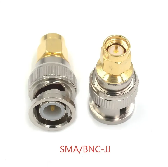
This diagram shows a field-tested transition solution that maintains <0.25dB insertion loss through the Ku band, providing reliable connection assurance for precision applications such as 5G FR2 or Wi-Fi 7 test fixtures
When precision counts—such as 5G FR2 or Wi-Fi 7 test fixtures—stay uniform in impedance and minimize interfaces. TEJTE’s SMA/BNC-JJ adapter (DC–12 GHz) is one of the few field-tested transitions proven to maintain < 0.25 dB insertion loss through the Ku band.
For broader measurement-chain consistency tips, the BNC T Connector Splitting Guide explains how reflections combine when multiple paths share a common node.
How long can an SMA-to-BNC jumper be without hurting your signal?
Length is where physics stops being polite. Every additional centimeter of coax between SMA and BNC connectors costs you amplitude, phase stability, and sometimes even instrument calibration accuracy.
A practical rule for RG316-class jumpers is to keep the total electrical length under 2 m for general RF work, and below 1 m for precision measurements above 3 GHz.
Loss overview (real TEJTE-tested data):
| Length | RG316 @ 1 GHz | RG316 @ 3 GHz | RG316D @ 3 GHz | Comment |
|---|---|---|---|---|
| 0.1 m | 0.09 dB | 0.17 dB | 0.20 dB | Ideal for scope front-ends |
| 0.3 m | 0.28 dB | 0.50 dB | 0.60 dB | Stable for short test leads |
| 0.5 m | 0.46 dB | 0.93 dB | 1.00 dB | Common lab jumper length |
| 1.0 m | 0.93 dB | 1.65 dB | 2.00 dB | Limit for high-GHz use |
| 2.0 m | 1.86 dB | 2.34 dB | — | Use only for low-MHz signals |
That’s why most professional test kits include 0.3 m, 0.5 m, and 1.0 m SMA-to-BNC cables. They’re long enough for flexibility yet short enough to avoid measurable phase drift.
Right-angle vs straight:
Right-angle SMA or BNC ends add roughly 0.05 dB extra loss but dramatically improve strain relief in tight panels or 19″ racks. The torque from stiff straight plugs often transfers to the instrument’s front connector, risking mechanical failure.
Temperature and routing tips
- Keep cables away from hot power supplies; FEP jackets of RG316 withstand +150 °C, but connectors typically derate near +120 °C.
- When routing near moving joints, use Velcro loops instead of tight zip ties—sharp bends below 15 mm R cause micro-cracks in PTFE dielectric.
- For extremely flexible setups, RG174 remains an option (28 mm min bend R, 2.85 mm OD), though it brings higher attenuation (~13 dB/100 m @ 100 MHz).
Engineering takeaway:
At 3 GHz, a 1 m RG316 jumper already wastes ≈ 30 % of power. Beyond 1 m, phase distortion starts to show even if amplitude looks fine. If you’re chasing amplitude accuracy within ±0.5 dB, keep SMA-to-BNC cables under 0.5 m and recalibrate quarterly.
Order exactly what you need without guesswork
Ordering SMA/BNC cables often confuses newcomers because both gender and direction matter. The wrong combination results in two males staring at each other—or worse, two females that can’t connect at all.
The table below summarizes standard SMA-BNC configurations used across TEJTE’s product line, simplifying part selection for RF designers.
| SMA Side | BNC Side | Typical Label | Orientation | Common Use |
|---|---|---|---|---|
| SMA-Male to BNC-Male | SMA-J / BNC-J / Cable | SMA-BNC-JJ | Straight | Analyzer to Scope link |
| SMA-Female to BNC-Mal | SMA-K / BNC-J | SMA/BNC-KJ | Straight | Module to Instrument |
| SMA-Female to BNC-Female | SMA-K / BNC-K | BNC/SMA-KKY | Bulkhead (panel) | Feed-through |
| SMA-Male to BNC-Female | SMA-J / BNC-K | Custom jumper | Right-angle or straight | Compact fixtures |
Length presets: 0.08 m, 0.1 m, 0.15 m, 0.3 m, 0.5 m, 1.0 m, and 2.0 m are standard. For automation racks or distributed RF nodes, keep consistent lengths so that calibration delays remain predictable.
Pro tip: For 18 GHz SMA interfaces, torque to 0.45 N·m and use gold-plated brass contacts only once per test shift to extend connector life.
When ordering, confirm:
- Impedance (Ω): always 50 Ω for SMA-based systems.
- Jacket & shield type: FEP for flexibility, dual-braid for EMI environments.
- Termination method: soldered, crimped, or press-fit—each affects long-term VSWR.
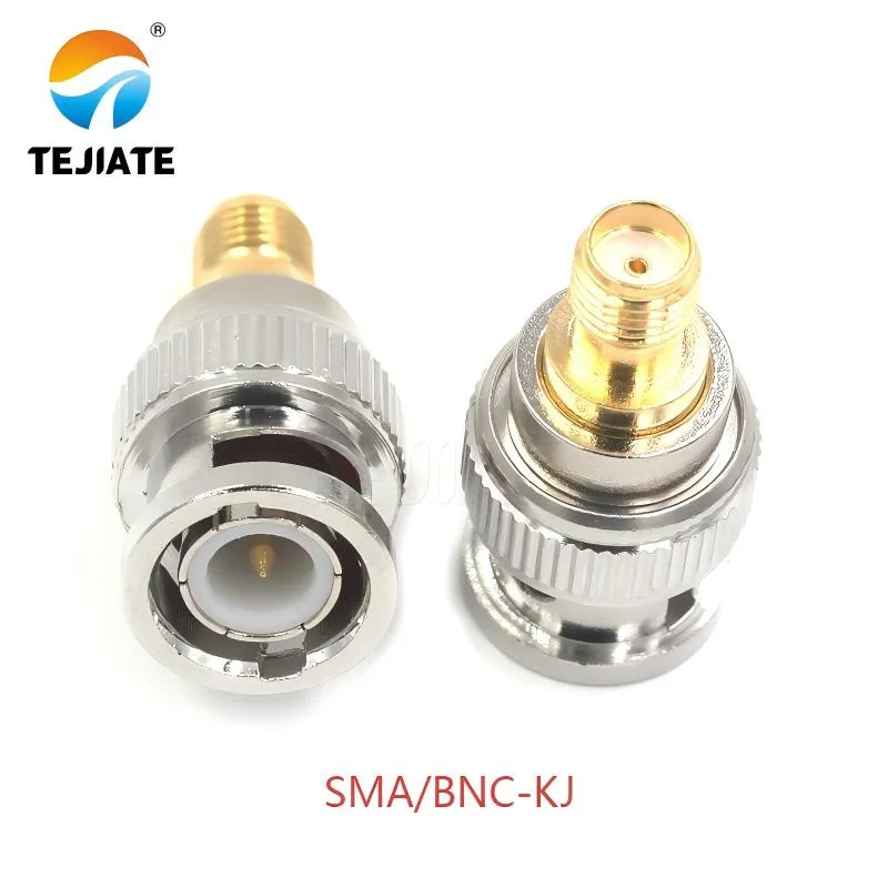
The product image shows TEJTE SMA/BNC-KJ, used to bridge SMA-F modules or pigtails to BNC-M instruments. Precision machining ensures low insertion loss and consistent 50 Ω matching across common bench frequencies.

This diagram details the mechanical structure of the through-the-wall adapter, including mounting nut and thread design, which can be neatly installed through 12mm cutouts while maintaining full 50Ω impedance continuity, suitable for test chassis and instrument panel applications
TEJTE’s engineering database maintains standardized part codes such as SMA/BNC-KJ (Part No. 06268) and BNC/SMA-KKY (Part No. 59683) with mechanical drawings, enabling quick specification matching during RF system design.
If you need a broader view of connector family compatibility, the Coaxial Cable Connector Overview provides impedance maps and thread-dimension references for SMA, BNC, and N-type series.
What recent RF bench updates could affect connector choices?

This diagram shows an SMA bulkhead connector that meets IP67 protection rating, maintaining 50Ω impedance continuity under humidity cycling tests, particularly suitable for RF testing applications in outdoor and automotive electronics fields
RF labs evolve quickly. Wi-Fi 7 and 5G FR2 testing now push into 6 GHz – 8 GHz bands, exposing weaknesses in older cable assemblies. Even small mismatches from a worn adapter can degrade modulation accuracy (EVM) by > 1 %.
Emerging trends:
- Cleaner 50-Ω paths: New analyzers require reference VSWR ≤ 1.05 up to 8 GHz. Older 75-Ω BNCs can’t meet that.
- Shorter jumpers: High-speed switch matrices integrate SMA ports directly, eliminating the need for multiple BNC links.
- Higher shielding: Labs running mixed RF + digital equipment prefer RG316D or LMR-series cables for better isolation.
- Thermal stability: With devices heating under test, FEP-jacketed coax keeps dielectric constants stable across −55 °C to +255 °C.
- IP67 field testing: Outdoor and automotive engineers increasingly request waterproof SMA bulkheads—TEJTE stocks IP67 versions that maintain 50 Ω continuity under humidity cycling.
Future-proofing strategy
- Use all-50 Ω signal paths.
- Replace aging BNC-only scopes with hybrid SMA/BNC front ends.
- Standardize on RG316D for precision; reserve RG174 for low-frequency logging channels.
- Plan service intervals: after 1,000 mating cycles, inspect both the SMA pin and BNC sleeve for plating wear.
By aligning with these trends, engineers ensure their benches remain compatible with next-generation RF standards while preserving measurement integrity.
FAQ
1. What does “RF cable assembly — BNC straight plug / SMA straight plug, 0.25 m” mean?
It describes a pre-terminated 50-Ω jumper made with RG316 coax. One end has a BNC-male plug, the other an SMA-male plug. The 0.25 m length is factory-cut for minimal loss (~0.23 dB @ 1 GHz). Both connectors use PTFE dielectric and FEP jackets for high-temperature durability.
2. Is it possible to get an SMA-F pigtail with a three-piece jumper set and a BNC-M end?
Yes. Order a custom assembly specifying SMA-female (bulkhead type), desired lengths (e.g., 3 in / 0.3 m / 3 ft), and RG316 or RG316D coax. TEJTE’s SMA-KWE and SMA-KE lines allow panel or PCB mounting with 8 mm thread length.
3. Adapter or dedicated cable — which gives better results on a scope input?
A dedicated SMA-to-BNC cable outperforms a chain of adapters. It eliminates two interfaces, reducing insertion loss by ~0.2 dB and reflection error by > 1 dB. Use adapters only for temporary setups or when gear sharing is unavoidable.
4. Can I run a 75-Ω BNC into a 50-Ω SMA path without damage?
Yes, but accuracy suffers. The mismatch reflection coefficient ≈ 0.2 (VSWR ≈ 1.45), which distorts high-frequency traces. Insert a 75 to 50 Ω matching pad or terminate properly at the instrument input.
5. How short is “short enough” for RG316 at high frequency?
For signals > 3 GHz, keep the jumper ≤ 0.5 m. Loss remains < 1 dB and return loss > 25 dB, preserving waveform integrity even on sensitive analyzers.
6. Do right-angle SMA or BNC connectors hurt performance?
Only slightly—expect +0.05 dB loss and a tiny VSWR rise (~0.02). The mechanical benefit and reduced strain usually outweigh that penalty in compact racks.
7. What length presets should I keep in stock for mixed labs?
Maintain 0.1 m, 0.3 m, 0.5 m, 1.0 m, and 2.0 m variants. Pair each with both straight and right-angle terminations. That covers 90 % of lab use cases without adding adapters.
Closing note
Whether you’re wiring a Wi-Fi 7 chamber, testing LTE radios, or just cleaning up your bench, the smartest move is minimizing interfaces and choosing the right cable for the right frequency band.
A single well-built SMA-to-BNC cable—using TEJTE’s RG316D dual-shield FEP coax—often does more for measurement precision than an entire set of fancy adapters.
Consistency, impedance matching, and mechanical reliability are the quiet trio that keep every RF engineer’s waveform honest.
Bonfon Office Building, Longgang District, Shenzhen City, Guangdong Province, China

A China-based OEM/ODM RF communications supplier
Table of Contents
Owning your OEM/ODM/Private Label for Electronic Devices andComponents is now easier than ever.
