BNC Coupler Selection Guide: Barrel, Feed-Through & Panel Choices
Nov 7,2025
Preface
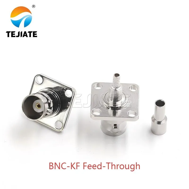
Figure as the opening of the document, visually introduces a key member of the BNC connector family - the feed-through connector. With its four-hole flange and robust structure, it symbolizes the importance of maintaining impedance consistency and mechanical stability in test systems, setting the stage for the discussion of the applicable scenarios for different connector types throughout the text.
Every engineer who’s spent time around coax test benches knows that the simplest parts often cause the longest head-scratching. You think you’re just joining two BNC cables, but one tiny coupler—barrel, feed-through, or panel-mount—can quietly decide whether your entire signal chain stays clean or starts to echo.
A BNC coupler isn’t glamorous, but it’s the mechanical handshake that keeps impedance consistent through your system. If you mismatch it, no amount of calibration can hide the ripple in your return loss trace.
At TEJTE, we’ve worked with dozens of variants such as the BNC-KK barrel coupler and BNC-KF four-hole feed-through, both machined from brass with nickel plating, PTFE insulation, and a bandwidth from DC–6 GHz. The moment you start pushing high-frequency or HD-SDI video signals, their small details—thread depth, nut torque, and contact plating—begin to matter. This guide shares what we’ve learned from real setups and where each style fits best.
When should you use a barrel coupler instead of a feed-through?
An inline barrel coupler—what most people casually call a female-to-female BNC—is for extending cables fast. No drilling, no mounting, just snap two male plugs together and keep measuring. For temporary setups or quick lab swaps, this tiny part saves hours.
A feed-through coupler, such as TEJTE’s BNC-KF (Q9-KF), takes a different role. It sits through a chassis wall or instrument panel, letting one side connect internally and the other externally. With its four-hole flange and nut-lock design, it stays solid even when the test rack shakes.
If you’re working in a measurement cabinet, that feed-through also becomes a grounding path. Its body bonds directly to the enclosure, reducing stray RF and mechanical strain on the mating jacks. Meanwhile, the BNC-KK barrel is best for quick extensions where flexibility outweighs permanence.
Both share 50 Ω nominal impedance, low insertion loss (≈ 0.15 dB @ 3 GHz), and reliable PTFE insulation rated to DC–6 GHz. The main difference? Mechanical life and serviceability. You can swap a loose barrel in seconds, but you’d never want to replace a worn feed-through behind a bolted panel mid-test.
Inline extension vs. enclosure pass-through use cases
Mechanical strain, serviceability, and field swaps
How do 50 Ω and 75 Ω couplers impact return loss on RF/video paths?
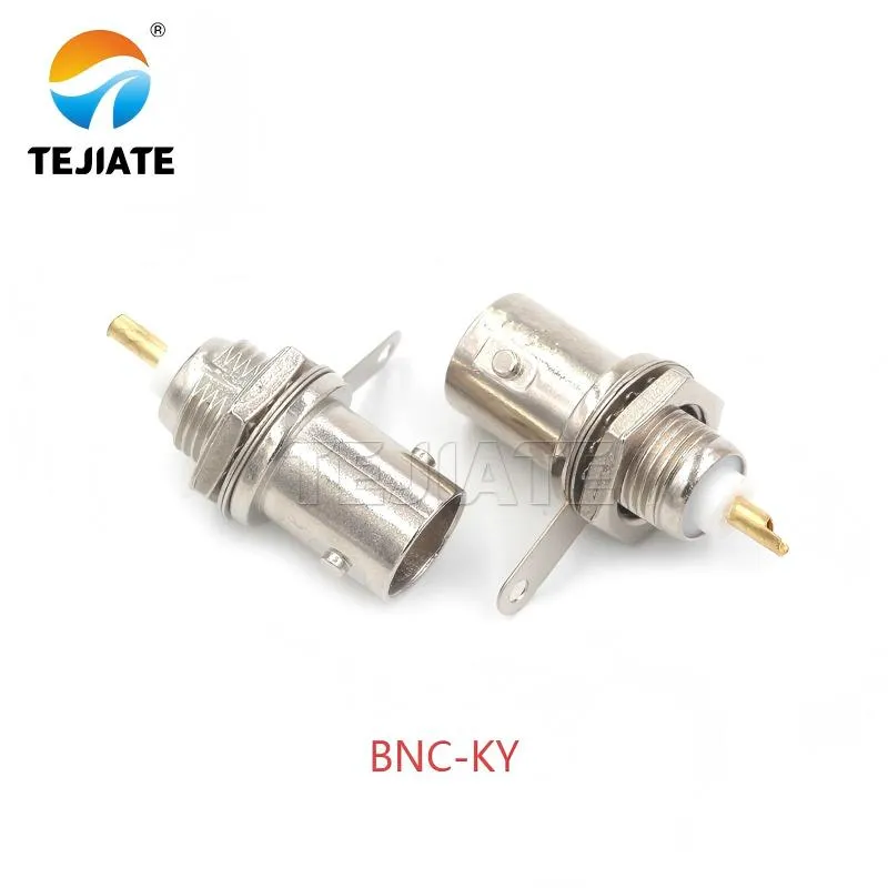
Figure appears in the "How do 50 Ω and 75 Ω couplers impact return loss on RF/video paths?" section. As a representative of 75Ω connectors, it visually supports the discussion in the context regarding impedance mismatch calculations, the impact on return loss (e.g., video ghosting), and the criticality of maintaining a pure 75Ω link for video signal quality.
When you connect a 50 Ω source through a 75 Ω coupler, you’re effectively throwing a small speed bump into your transmission line. The reflection coefficient,
[ \Gamma = \frac{Z_\text{c} – Z_0}{Z_\text{c} + Z_0}, ]
tells you how much of the signal bounces back. Even a tiny mismatch can blur the rising edge of a pulse or add ghosting on a video waveform.
Here’s a quick look at realistic values based on TEJTE coupler specs and standard system impedances:
| System Z₀ (Ω) | Coupler Zc (Ω) | Γ | Return Loss (dB) | Condition |
|---|---|---|---|---|
| 50 | 50 | 0 | ∞ | Perfect match |
| 50 | 75 | 0.20 | 13.98 | High mismatch |
| 75 | 75 | 0 | ∞ | Perfect video chain |
| 75 | 50 | 0.20 | 13.98 | High mismatch |
Think of return loss like a mirror: a good line shows almost no reflection. Once RL drops below 20 dB, reflections start to paint faint duplicates on your scope.
In RF test chains, keep the full 50 Ω path—BNC-KK or BNC-KY couplers with RG58 or LMR240 cable—to stay comfortably above 25 dB even around 3 GHz.
For video or HD-SDI, use 75 Ω couplers such as the broadcast-grade variants that pair cleanly with RG59. The same rule appears in TEJTE’s BNC T Connector Guide when splitting lines—the closer the impedance match, the sharper the image.
Inputs / calculation fields
Recommended RL thresholds
Which female-to-female orientation avoids extra adapters?
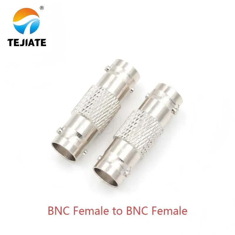
Figure is located in the "Which female-to-female orientation avoids extra adapters?" section. It clearly shows the form factor of the most common "barrel" coupler, helping readers understand its physical difference from feed-through connectors and providing a visual reference when discussing connector orientation, enclosure wiring, and avoiding adapter stacks.
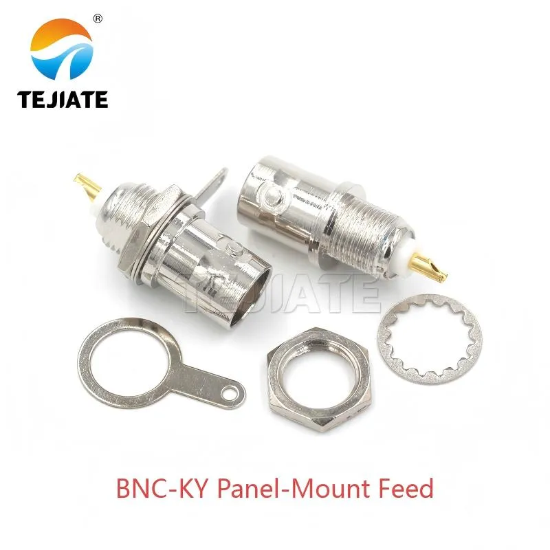
Figure follows Figure 3, showcasing another main type of connector - the panel-mount feed-through. It is used in the document to illustrate how to simplify enclosure wiring, provide stable grounding, and achieve neat and reliable permanent installation by using feed-through connectors, contrasting with the temporary use of barrel connectors.
It sounds trivial until you’re wedged behind a rack full of coax lines: one flipped connector orientation can waste half an hour. A BNC female-to-female barrel such as the TEJTE BNC-KK connects two male plugs inline; a panel-mount feed-through (BNC-KF or BNC-KY) uses a threaded body through an 11.7 mm hole with a nut and washer to lock it flush to the chassis.
Mounting orientation matters because BNC bayonet tabs aren’t symmetrical. Consistent alignment along a row of couplers keeps patch cables straight and reduces mechanical cross-stress.
Panel clearance and labeling to prevent reversals
Always mark impedance on the chassis—“50 Ω TEST IN” or “75 Ω VIDEO OUT.” It saves mistakes during maintenance.
If you follow a simple rule—feed-throughs at the panel entry, barrels in the inline section—you’ll rarely need extra adapters. The layout becomes intuitive for any technician who inherits your rack later.
Can a panel-mount feed-through simplify enclosure wiring?
Engineers love clean wiring, and nothing ruins it faster than dangling coax tails through a half-closed panel. A panel-mount feed-through coupler—like TEJTE’s BNC-KF—solves this elegantly. Its four-hole flange and locking nut let it sit flush through metal walls, keeping both the mechanical and RF paths stable.
Inside, the BNC-KF maintains 50 Ω nominal impedance, handles up to DC–3 GHz, and keeps insulation resistance ≥ 5000 MΩ. With a contact resistance below 1.5 mΩ on the inner conductor, it’s solid enough for long-term monitoring setups. You’ll usually see these feed-throughs on measurement racks, network analyzers, or control cabinets where cable swaps happen frequently.
A small but critical advantage: grounding. When mounted on bare metal, the coupler’s body bonds directly to the chassis. If the panel is painted or powder-coated, scrape a small ring around the hole to ensure electrical continuity. The result is fewer hum loops and tighter shielding at high frequencies.
bnc feedthrough connector vs. bnc panel mount coupler
The terms are often used interchangeably, but subtle differences exist. A “feed-through connector” normally includes both male and female interfaces through a bulkhead. A “panel-mount coupler” is usually female-to-female, such as TEJTE’s BNC-KY or BNC-KF, built for secure panel anchoring. Both provide the same electrical performance but vary in mounting geometry.
When designing your enclosure, keep enough clearance for the coupling nut and cable boot—about 12 mm depth behind the plate usually works. If you want a quick visual comparison of assembly and sealing, check the BNC Bulkhead Connector Guide, which breaks down mounting torque, O-ring placement, and grounding best practices.
Gasket / O-ring / torque & surface preparation
What frequency and insertion-loss limits should you budget?
Every connection costs something. At low frequency you might never notice, but once you reach multi-GHz bandwidths, even a few tenths of a dB start adding up. The TEJTE BNC-KK inline coupler has a typical insertion loss ≤ 0.15 dB @ 3 GHz, excellent for 50 Ω test systems. The BNC-KF feed-through performs similarly through its 0–6 GHz range.
When estimating a system’s total loss, combine cable attenuation and connector losses. Below is a quick summary using verified TEJTE cable data:
| Cable Type | Impedance (Ω) | Attenuation @ 3 GHz (dB/m) | Notes |
|---|---|---|---|
| RG58 | 50 | 1.05 | Standard lab coax, flexible |
| RG59 | 75 | 0.93 | Preferred for HD-SDI video |
| RG141 | 50 | 0.78 | Semi-rigid, low-loss lab cable |
| LMR240 | 50 | 0.47 | Low-loss outdoor option |
If your target signal-path loss budget is under 1.5 dB, you can easily stay within spec by keeping total cable length below 2 m and using one coupler. Need longer runs? Step up to LMR240 or similar low-loss types to gain a comfortable margin.
Small mismatches compound, so it’s smart to verify each segment individually. A 50 Ohm BNC Terminator Guide explains why proper termination after coupling keeps reflections from accumulating in long chains.
bnc barrel connector IL vs. coax run
Loss budgeting with jumpers; minimize stacked joints
Here’s a simple formula used in many labs:
[ IL_\text{total} = \alpha_\text{cable} \times L + IL_\text{coupler} ]
At 3 GHz, for a 1.5 m RG58 jumper (1.05 dB/m) plus one BNC-KK coupler (0.15 dB):
[ IL_\text{total} = 1.05 \times 1.5 + 0.15 = 1.725 dB ]
That’s still within tolerance for most RF setups below 6 GHz. Replace RG58 with LMR240 (0.47 dB/m) and the same assembly drops to 0.855 dB, a huge improvement.
If you’re routing video, switch to RG59, maintain a 75 Ω path, and your SDI line will stay crisp even over extended distances.
How do you extend a BNC run without degrading the signal?
| Field | Example | Meaning |
|---|---|---|
| Frequency (GHz) | 3 | Operating frequency |
| Cable Type | RG58 / RG59 / LMR240 | Select impedance match |
| Cable Length (m) | 1-3 | Physical distance |
| Cable Loss (dB/m) | From table above | Frequency-dependent |
| Coupler Loss (dB) | 0.15 | Typical TEJTE BNC-KK |
| Total IL (dB) | α × L + IL(coupler) | Overall system loss |
Acceptance criteria
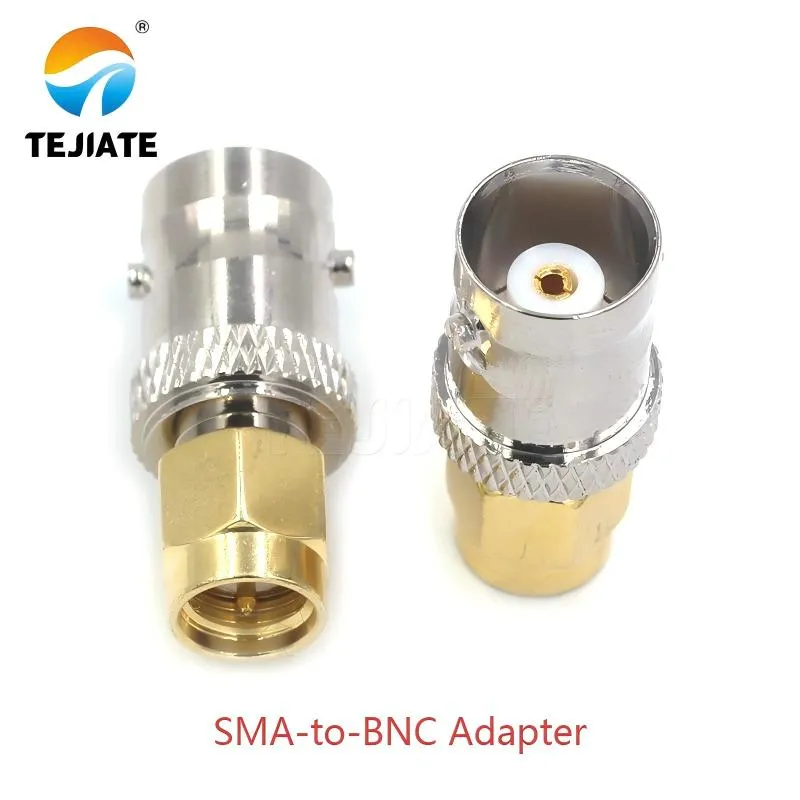
Figure is mentioned in the practical tips section of "How do you extend a BNC run without degrading the signal?" It reminds readers that in systems using both SMA and BNC interfaces, dedicated adapter guides should be consulted to optimize connections and avoid unnecessary connector stacking and the associated performance degradation.
Practical tip
Do HD-SDI and 3G/12G video chains need 75 Ω precision couplers?
High-definition video demands discipline. A single mismatch can smear edges across a 1080p waveform. In broadcast and SDI systems, the signal rides a 75 Ω path, not 50 Ω. That means every bnc coupler in the line—barrel, feed-through, or patch panel—must also be 75 Ω, not “close enough.”
TEJTE’s precision 75 Ω BNC series keeps return loss above 25 dB through 3 GHz, comfortably supporting 3G/12G SDI. The key difference lies in the pin diameter and dielectric spacing. A 50 Ω coupler physically mates, but the geometry mismatch creates reflections around 14 dB RL—barely acceptable even for analog composite.
Here’s a quick visual of what happens when the wrong coupler sneaks in:
SDI compatibility and return-loss spec
For 3G-SDI, RL ≥ 20 dB is bare minimum; for 12G-SDI, target ≥ 26 dB. The TEJTE 75 Ω BNC coupler chain with RG59 (0.93 dB/m @ 3 GHz) meets that without extra EQ. When mixing test instruments (50 Ω) and broadcast feeds (75 Ω), use a matched pad or transformer between domains.
If you’re unsure which grade of connector your rack uses, compare inner-pin diameter: 50 Ω pins ≈ 1 mm, 75 Ω ≈ 0.7 mm. This tiny difference explains why the “works but looks soft” symptom shows up on monitors.
Brand tolerance and plating impact
Could an inline coupler solve tight-rack pigtail issues?
When racks fill up, there’s never enough space for a full cable loop. That’s where a bnc inline coupler helps—acting as a short, rigid bridge instead of a floppy pigtail. It saves space and reduces bend stress near ports.
Imagine you have a dense test panel with adjacent BNC ports. Instead of adding another short jumper, plug two male connectors directly into a TEJTE BNC-KK barrel. At just 32.7 mm length and under 0.15 dB loss at 3 GHz, it behaves like a solid splice with minimal phase shift. The bayonet locks also reduce strain when rack doors close against tight harnesses.
bnc inline coupler vs short pigtail
Bend radius and port stress
Field repair vs permanent retrofit
What mistakes cause intermittent faults after coupling?
Intermittent dropouts are the bane of every RF lab. Nine times out of ten, the fault traces back to mechanical details around the bnc coupler. Here’s what goes wrong most often:
- Mixed impedances (50 Ω and 75 Ω) accidentally stacked. They fit physically but introduce return loss around 14 dB.
- Loose bayonet locks. If the plug doesn’t click, it’s not fully seated—expect noise bursts when the bench vibrates.
- Too many adapters in series. Every joint adds tiny capacitance shifts; stack three and your S11 curve will start rippling.
- Un-scraped paint under panel-mounts. Without clean metal contact, ground loops form.
- No labeling. Unmarked lines invite mismatched impedances and wrong-channel patches.
A few quick checks save hours of debugging: verify continuity (< 1 Ω), perform a “wiggle test” to spot loose bayonets, and run a basic S11 measurement at your highest operating frequency. Anything above −20 dB reflection means something needs tightening or replacement.
Continuity, wiggle test, and basic S11 smoke test
Mixed 50/75 Ω chains and why they still trip people up
Document coupler use for consistent maintenance
How should you document coupler use so maintenance stays consistent?
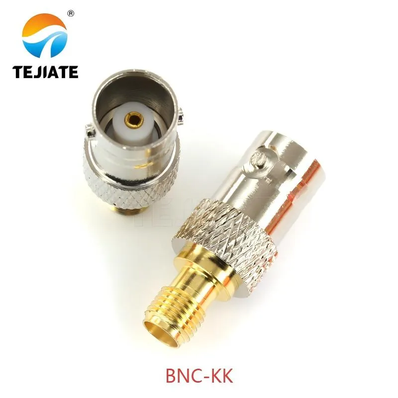
Figure appears in the chapter on connector documentation management at the end of the document, serving as an example of a typical component that needs to be labeled and recorded (code "F/F-K"). It re-emphasizes that even simple barrel couppers require correct selection, usage, and documentation to maintain the consistency and traceability of the entire test system.
Most labs focus on measurement precision, but documentation discipline is what keeps that precision alive. Every bnc coupler—barrel, feed-through, or inline—should be traceable. Without a clear record, technicians waste hours guessing which part failed or which impedance path was intended.
A simple labeling schema works wonders. Mark each coupler directly on its panel or cable end with its role (“50 Ω Test In,” “75 Ω Video Out”) and installation date. For bulkhead versions like TEJTE BNC-KF, a tiny laser-etched tag or printed label ring fits around the flange without interfering with the bayonet lock.
Label schema, rack diagram, and change log
Use a short code system:
- “F/F-K” = female-to-female barrel coupler (e.g., BNC-KK)
- “F/F-KF” = feed-through panel coupler
- “75V” = video-grade 75 Ω line
- “50R” = RF 50 Ω test line
Keep these notations on a rack diagram pinned near the equipment. Each update—adding a new instrument, swapping a cable, changing a feed-through—goes into a change log. Over time, this creates a living history of your signal paths.
If you’d like to see how a properly documented system looks, the BNC Bulkhead Connector Guide includes panel layout samples that illustrate clean grounding zones and label positioning.
“One-page handoff” for field technicians
A one-page handoff summarizes the essentials: coupler type, impedance, installation point, date, and technician initials. It travels with the instrument wherever it goes. When that analyzer ships for calibration, the next engineer instantly knows what’s inside and what must be re-verified.
This small administrative habit prevents bigger technical headaches. A mislabeled bnc female to female coupler or an unrecorded 75 Ω adapter can derail test repeatability across teams. Documentation, in the RF world, is a hidden gain control—it amplifies consistency.
FAQ: Common Questions about BNC Couplers
Can a 50-ohm BNC coupler be used with 50-ohm cable?
Yes. Keep the entire chain—source, cable, bnc coupler, and load—at 50 Ω.
A TEJTE BNC-KK barrel adds only about 0.15 dB insertion loss at 3 GHz.
Avoid stacking multiple joints; every extra interface slightly raises VSWR.
Do I need an HD-SDI/3G-rated coupler for broadcast video?
What does a BNC coupler actually do in a lab rack?
Where should I buy a BNC female-to-female coupler for cable extension?
Choose reputable RF or broadcast suppliers who publish specs such as impedance, frequency range, and return-loss data.
Look for real numbers—like TEJTE’s DC–6 GHz bandwidth—rather than vague “high-frequency” claims.
Is a coupler the same as a barrel connector?
Will a coupler limit my high-frequency measurements?
Every joint has bandwidth limits, but a precision coupler’s loss is tiny compared with cable loss.
At 3 GHz, a BNC-KK adds ≈ 0.15 dB; LMR240 coax adds about 0.47 dB per meter. Keep total loss under 1 dB per segment for accurate readings.
Can I mix 50 Ω cable with a 75 Ω coupler as a quick fix?
Closing Notes
A BNC coupler looks like the smallest part of your RF setup, yet it quietly dictates how stable your measurements, videos, or communication signals remain. Whether it’s a barrel, feed-through, or panel-mount version, precision machining and proper documentation make the difference between clean data and constant retesting.
Incorporating the right TEJTE parts—BNC-KK, BNC-KY, BNC-KF—with proper cable choices such as RG58, RG59, or LMR240 ensures both mechanical reliability and signal integrity up to 6 GHz.
For a broader view of connector families and impedance matching principles, explore the RF Coaxial Cable Guide and N-Type Connector Outdoor Guide on tejte.com. Together, they round out the complete ecosystem of high-performance RF connectivity.
Bonfon Office Building, Longgang District, Shenzhen City, Guangdong Province, China

A China-based OEM/ODM RF communications supplier
Table of Contents
Owning your OEM/ODM/Private Label for Electronic Devices andComponents is now easier than ever.
