SMA Male Connector Guide: Torque, Crimping & Selection
Oct 2,2025
How do I verify my device port matches an SMA male?
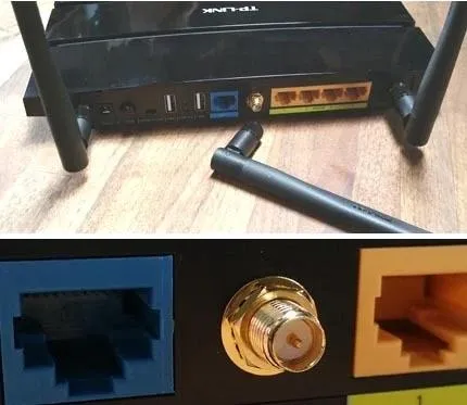
under the key question "How do I verify my device port matches an SMA male?". Serving as the opening graphic, it introduces the importance of correctly identifying connector gender and polarity (SMA vs. RP-SMA), which is the first step to avoid selection errors and device damage.
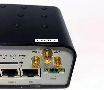
immediately following Figure 1. It further assists users in the visual identification of an SMA Male connector through a diagram, emphasizing that getting the right SMA male connector isn't just about grabbing something that "looks close enough," and a wrong call on gender or polarity can waste hours in the lab or damage an expensive board.
Polarity ID: SMA vs RP-SMA
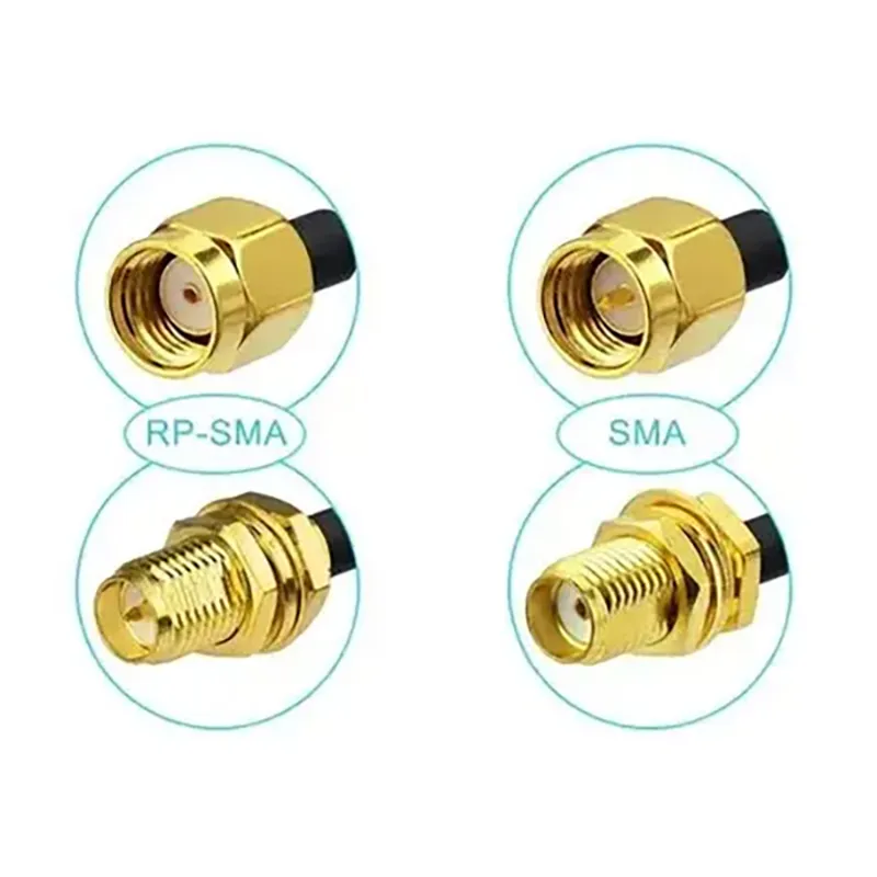
titled "Polarity ID: SMA vs RP-SMA". It clearly displays the center contact structure of SMA and RP-SMA connectors side-by-side, visually illustrating how the RP-SMA variant flips the pin and socket arrangement. The document notes that this is where it trips people up, and RP-SMA male connectors are common in WiFi routers and consumer antennas.
An SMA male connector has external threads and a center pin. Its mate, the sma female connector, comes with internal threads and a socket instead of a pin. Straightforward so far.
But here’s where it trips people up: the reverse polarity (RP-SMA) variant. RP-SMA flips the pin and socket arrangement, which makes many installers assume they’re dealing with a standard SMA. In WiFi routers and consumer antennas, it’s common to see RP-SMA male connectors—they look like regular SMA males but lack the pin. If you mix the two, you’ll end up with a threaded connection that passes no signal at all.
Field note: I’ve personally seen technicians try to “make it fit” by forcing an SMA male into an RP-SMA port. The threads seemed fine, but the result was a bent pin and a costly device return. Always double-check polarity markings before placing an order.
Plug-and-play pairs with SMA female and M-F adapters
In most setups, your SMA male plug mates directly with a standard sma female connector. But when you need flexibility—like extending a run or reducing wear on a sensitive PCB jack—you’ll often rely on an SMA male to female adapter.
For instance:
- Working on a bench test? Add a male-to-female coupler to protect the board-mounted jack.
- Trying to reach an antenna mounted further away? Use an sma extension cable instead of stacking rigid adapters. This reduces stress and avoids extra signal loss.
For reference, TEJTE’s SMA connector catalog lists both straight and right-angle SMA male options, so you can match the connector to your layout without improvising.
How do I match impedance and band (50 Ω vs 75 Ω)?
Pairing with 50-ohm coax across 900/2.4/5.8 GHz
Most SMA male connectors from TEJTE are specified for 0–18 GHz, which covers the bands engineers deal with daily:
- 900 MHz for GSM, IoT modules, and telemetry
- 2.4 GHz for WiFi, Bluetooth, and Zigbee
- 5.8 GHz for drones, ISM devices, and high-speed data links
The TEJIATE SMA models are rated with VSWR ≤1.10–1.20, meaning reflections are kept low and efficiency stays high when used in a 50Ω system. That’s why nearly all telecom, aerospace, and defense designs rely on 50Ω SMA connectors as their baseline.
If you’re unsure, it’s almost always safe to stick with a 50 ohm SMA male connector unless your datasheet explicitly calls for 75Ω.
Symptoms of mismatch
What happens when you plug a 50Ω SMA male into a 75Ω port? It might feel secure, but the signal path tells another story:
- Return loss spikes, leading to poor power transfer
- Digital systems start showing error bursts
- Amplifiers produce audible noise and lower gain
I once tested a mismatched setup at 2.4 GHz. The link showed almost 3 dB of extra loss—that’s basically cutting your transmit power in half. In a lab you might tolerate it, but in the field it could be the difference between a stable connection and no link at all.
Should I choose straight or right-angle for my layout?
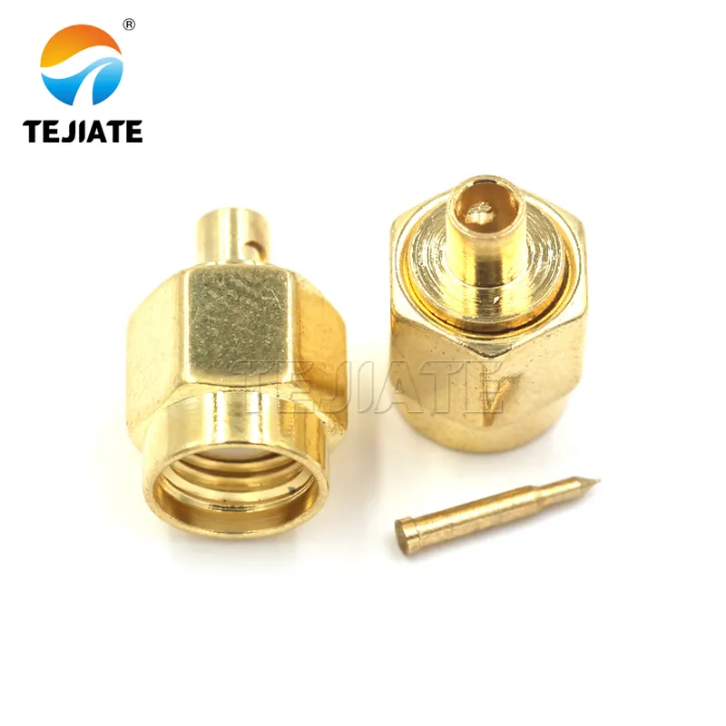
titled "Straight SMA Connector". It serves as an example of a straight SMA male connector during the discussion "Should I choose straight or right-angle for my layout?". The document states that straight SMA males are compact and reliable, making them ideal when your PCB or panel has enough clearance.
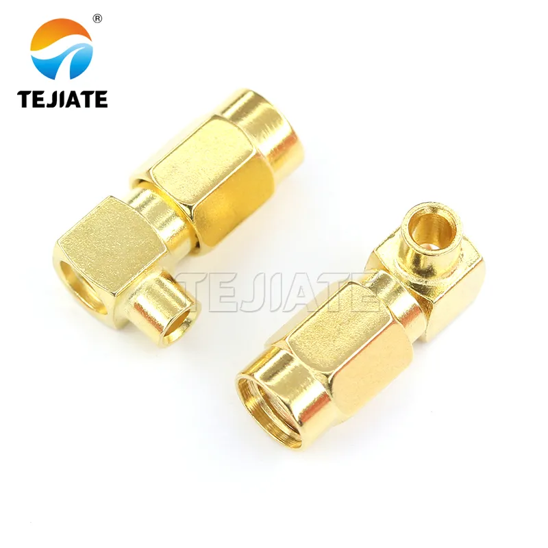
titled "Right-Angle SMA Connector". It shows a physical right-angle SMA male connector. The document points out that in handheld radios, rack-mounted analyzers, or tight communication boxes, a right-angle SMA male can prevent sharp bends that would otherwise stress the coax.
Space/strain trade-offs in enclosures and handhelds
Straight SMA males are compact and reliable, making them ideal when your PCB or panel has enough clearance. But in handheld radios, rack-mounted analyzers, or tight communication boxes, a right-angle SMA male can prevent sharp bends that would otherwise stress the coax.
From TEJIATE’s catalog:
- SMA-KWE right-angle male (gold-plated brass with PTFE dielectric) is rated for about 500 mating cycles.
- Stainless SMA-JWJ elbow connectors offer much higher durability, with ≥1000 cycles, and resist corrosion even after 48-hour salt spray tests.
One lesson from field deployments: forcing a coax like RG174 or RG316 to bend right at the connector usually ends up with broken shielding or higher VSWR. A right-angle body solves that at the design stage.
When to switch to a short extension
Even a right-angle connector won’t solve every mechanical challenge. If your antenna or cable run still demands a bend that exceeds the coax’s rated radius, it’s smarter to add an sma extension cable. A short jumper absorbs mechanical strain, while the SMA male connector at the device stays aligned and undamaged.
For example, using a 10–15 cm RG316D jumper is often cheaper than repairing a cracked PCB-mounted jack. TEJTE covers this solution in their SMA Antenna Extension Cable Guide. It’s one of those small preventive steps that pays off long-term.
When is a connector better than an adapter path?
Loss and reliability vs SMA adapters (BNC/N paths)
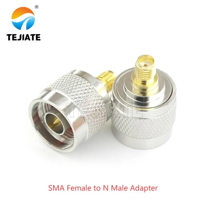
appearing as an example of an adapter during the discussion "When is a connector better than an adapter path?". The document compares the pros and cons of using a direct connector versus an adapter path (e.g., SMA to BNC, SMA to N) in terms of insertion loss, reflection points, and reliability, noting that every extra joint adds insertion loss, reflection points, and another possible failure.
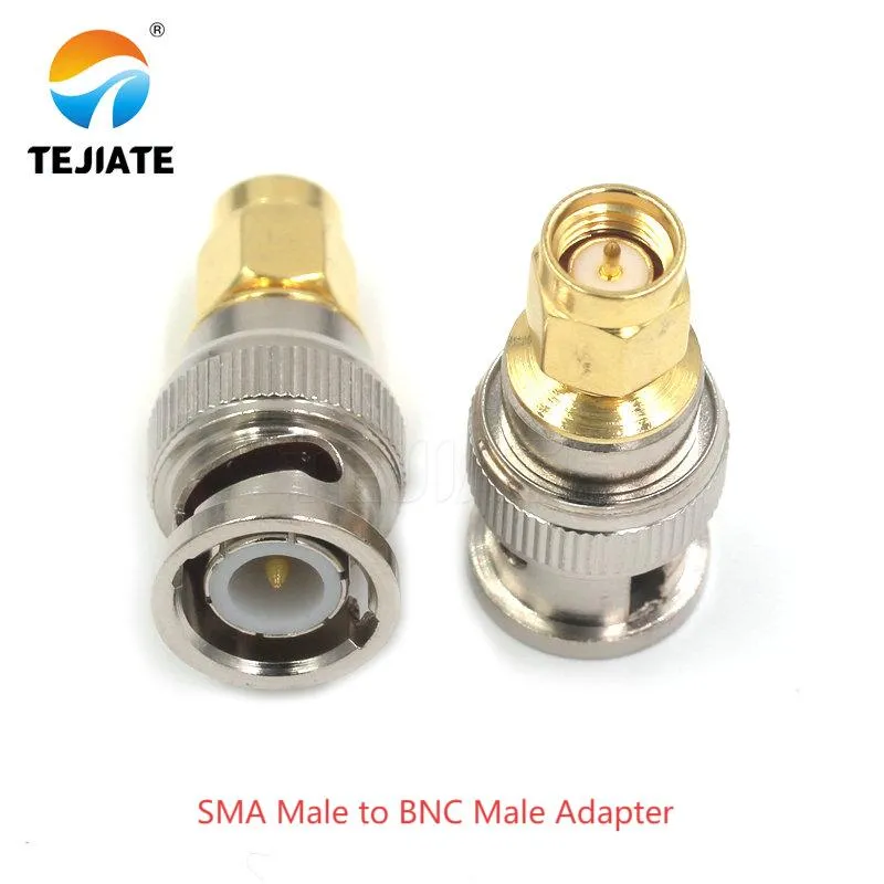
serving as another adapter example. The document uses a common scenario (e.g., you've got an SMA male connector but the instrument only accepts BNC) to illustrate that while an adapter solves it quickly, each added junction introduces resistance and reflection. TEJTE's internal tests measured around 0.25 dB extra insertion loss from stacked adapters at 6 GHz.
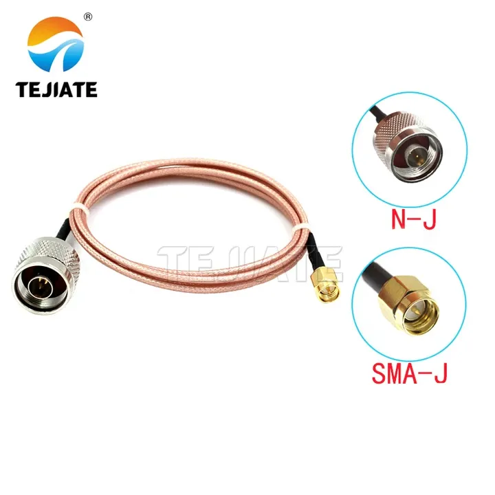
showing the assembly or connection diagram of an SMA to N-Type adapter. It continues the discussion on the pros and cons of the adapter path, emphasizing that whenever possible, design with the correct connector at the start—be it an SMA PCB connector or a bulkhead-mounted SMA male—to reduce transition points and potential failures.
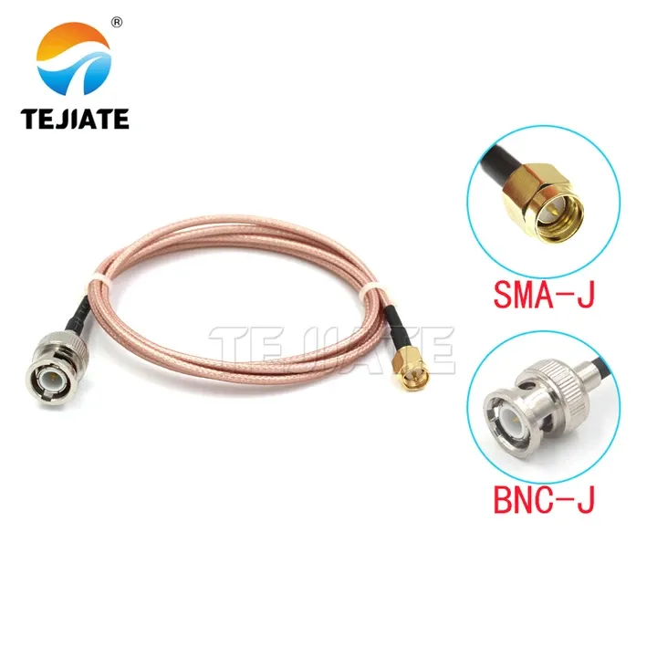
showing the assembly or connection diagram of an SMA to BNC adapter. It also serves as an adapter example for comparison with using direct connectors. The document suggests that for outdoor antenna runs, order a custom SMA male to N male jumper from TEJTE's adapter cable assemblies rather than stacking SMA-to-BNC and BNC-to-N adapters.
Take a common example: you’ve got an sma male connector but the instrument only accepts BNC. Sure, an sma to bnc adapter solves it in seconds. The issue is that each added junction introduces resistance and reflection. TEJTE’s internal 6 GHz tests measured around 0.25 dB extra insertion loss from stacked adapters. That might seem minor, but across long coax runs or precision RF tests, it’s enough to skew results.
The same goes for daisy-chaining—like SMA → BNC → N-type. The more transitions, the more points of failure under vibration or outdoor conditions. Whenever possible, design with the correct connector at the start—be it an sma pcb connector or a bulkhead-mounted SMA male.
For detailed selection tips, check TEJTE’s blog: SMA to BNC Adapter Guide.
Shortest chain examples
Here are practical ways to avoid overusing adapters:
- PCB test boards: solder in a dedicated sma pcb connector instead of hanging adapters off the edge.
- Outdoor antenna runs: order a custom SMA male to N male jumper from TEJTE’s adapter cable assemblies rather than stacking SMA-to-BNC and BNC-to-N adapters.
- Rackmount analyzers: if you need a sacrificial layer to protect the expensive front jack, add a single sma male to female adapter—but keep it at that.
A simple rule of thumb: one clean connection beats three temporary fixes every single time.
What torque and materials should I specify?
Torque vs Material Table
| Connector Material | Recommended Torque (N·m) | Cycle Life (Mating) | Wrench Size |
|---|---|---|---|
| Brass, gold-plated (standard) | 0.56 – 0.79 | ~500 cycles | 5/16 in (8 mm) |
| Stainless steel (IP67 grade) | 0.90 – 1.13 | ≥1000 cycles | 5/16 in (8 mm) |
Data verified against TEJTE’s SMA connector line and aligned with MIL-STD-348 guidelines.
Why it matters:
- Brass, gold-plated SMA males (such as TEJTE’s SMA-KWE series) deliver excellent electrical performance but softer threads. Over-torqueing here is the fastest way to shorten service life.
- Stainless steel SMA male connectors (e.g., the SMA-JWJ elbow) are built for harsher environments, handle higher torque safely, and are often the go-to choice for IP67-rated outdoor enclosures.
From my own bench work: I once watched a junior engineer tighten a brass SMA with pliers “just to be safe.” Within a week the threads seized, and the connector had to be replaced. A properly calibrated 5/16-inch torque wrench would’ve saved both the connector and the day.
How do I crimp an SMA male correctly?
Crimp Spec Card
| Parameter | Spec Range (RG316 example) | Pass/Fail Criteria |
|---|---|---|
| Jacket strip length | 6.0 ± 0.2 mm | Braid exposed cleanly |
| Dielectric strip length | 3.0 ± 0.2 mm | No PTFE nicks |
| Center conductor length | 2.5 ± 0.1 mm | Flush with pin, no burrs |
| Crimp height (hex die) | 1.72 – 1.80 mm | Matches gauge spec |
| Pull strength | ≥ 20 N | Holds under pull, no slip |
Formula for acceptance is straightforward:
Pass = (all strip dimensions in range) ∧ (pull ≥ 20 N) ∧ (visual inspection shows no cracks or misalignment).
Note: These values are based on TEJTE’s SMA crimp process and align with common RF cable assembly standards.
Tooling & sampling
Always use the correct hex die for the cable you’re working with. For RG316, that means a 1.72 mm hex crimp. A mismatched die not only produces weak crimps but can damage the ferrule permanently.
In production, TEJTE applies 5% sampling per batch—that includes visual checks, crimp height measurement, and pull tests. If you’re running smaller jobs in the lab, it’s worth investing in a calibrated crimp tool plus go/no-go gauges. The upfront cost pays off the first time you avoid re-terminating an entire batch of cables.
Field tip: when stripping coax, leave a slight chamfer on the dielectric edge. This makes pin insertion smoother and reduces the chance of shaving PTFE into the connector cavity. It’s a tiny adjustment, but it keeps your assembly clean and stable at higher frequencies.
For more details on crimping best practices, check TEJTE’s blog: How to Use Crimp Connectors.
How do I pick between PCB, bulkhead and antenna mounts?
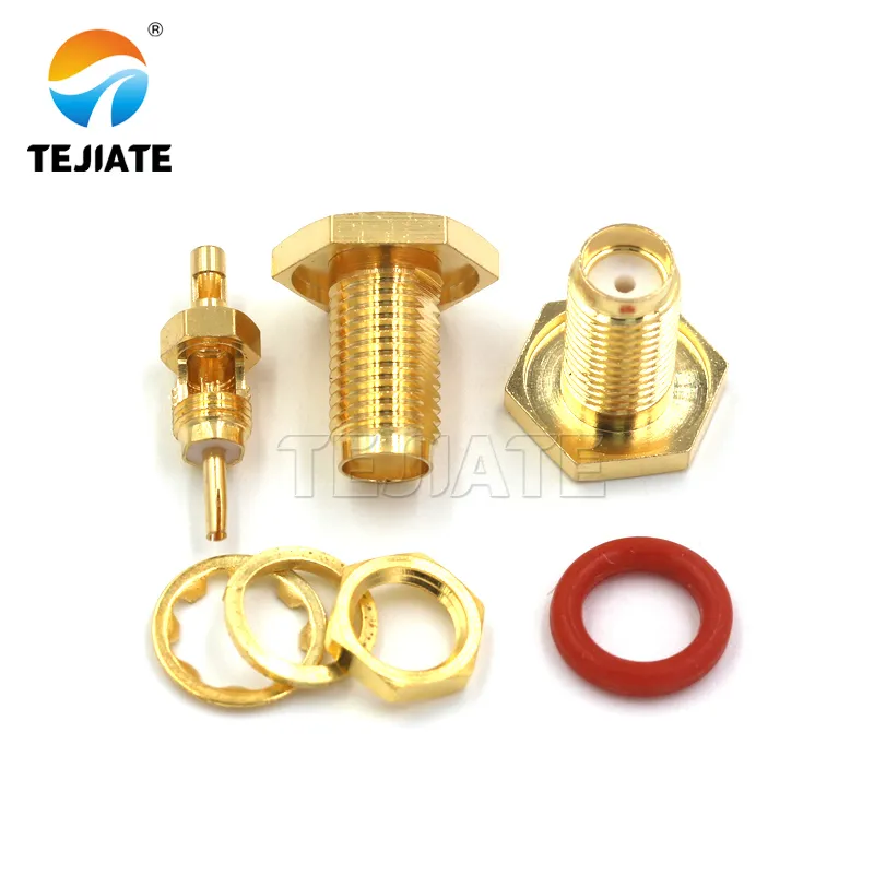
appearing during the discussion "How do I pick between PCB, bulkhead and antenna mounts?". It shows a bulkhead-mounted SMA male connector with a waterproof O-ring. The document states that for enclosures, a bulkhead SMA male connector is the cleanest way to pass RF through a panel, and mentions that TEJIATE's SMA-KKY bulkhead series includes waterproof O-rings and locking nuts that achieve IP67 sealing.
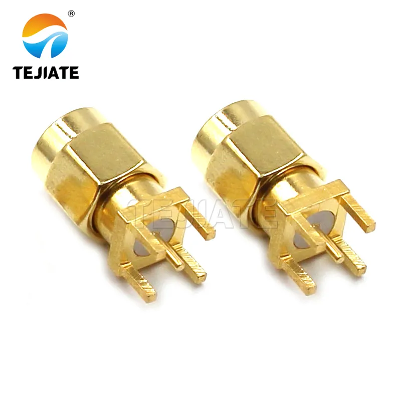
below Figure 10. It shows an SMA male connector designed for PCB mounting. The document elaborates in this section that when it comes to SMA PCB connectors, board layout is critical, and you'll need to follow the manufacturer's keep-out design around the RF launch to maintain a true 50Ω transition.
PCB keep-outs and reflow notes
When it comes to sma pcb connectors, board layout is critical. To maintain a true 50Ω transition, you’ll need to follow the manufacturer’s keep-out design around the RF launch. TEJTE’s SMA PCB series uses PTFE insulators and brass gold-plated housings, with frequency ratings up to 18 GHz, making them suitable for both prototyping and production.
A practical note: reflow soldering can stress the dielectric if your temperature profile exceeds about 260 °C. Always confirm the thermal window against the connector datasheet. One trick engineers often use is a small ground relief under the pad. It slightly reduces parasitic capacitance and improves return loss at microwave frequencies.
For reference, TEJTE’s PCB-mounted SMA connectors include footprints and solder recommendations, helping designers avoid costly signal integrity issues.
Bulkhead cutouts, O-rings, grounding
For enclosures, a bulkhead SMA male connector is the cleanest way to pass RF through a panel. TEJIATE’s SMA-KKY bulkhead series includes waterproof O-rings and locking nuts that achieve IP67 sealing.
When planning bulkhead integration, consider:
- Cutout size: most SMA bulkheads require 6.35–6.5 mm holes
- O-ring compression: enough to seal, but not so tight that it deforms the insulator
- Ground continuity: the nut and washer should make firm contact with the chassis to minimize EMI leakage
Antenna interface considerations
How can I guarantee reliability outdoors or in high-vibration setups?
Stainless vs brass: corrosion and vibration
Gold-plated brass connectors are excellent for low-loss RF, but outdoors they wear faster. Threads can tarnish or deform after months of wind, rain, or salt. That’s why TEJTE also supplies stainless steel SMA male connectors, such as the SMA-JWJ series, which are rated for ≥1000 mating cycles and proven in 48-hour salt spray tests.
If you’re selecting an sma connector for antenna deployments, stainless steel is almost always worth the investment. It resists corrosion, maintains torque under vibration, and pairs well with IP67-sealed housings for reliable long-term service.
I’ve seen marine IoT projects where brass connectors failed within a season—threads dulled, plating discolored, and the link became unstable. Switching to stainless solved the issue for years without replacement.
You can find outdoor-ready designs in TEJTE’s SMA connector catalog.
When to use a short jumper instead of rigid adapters
Another way to boost reliability is reducing mechanical stress. Mounting a heavy antenna directly on a board-mounted SMA often cracks solder joints or strains the bulkhead. Instead, insert a short sma extension cable.
A flexible jumper absorbs bending and vibration, keeping the device-side connector safe. For instance, a 15 cm RG316D jumper with molded strain relief is cheap insurance against downtime. TEJTE explains this practice in their blog: SMA Antenna Extension Cable Guide.
When to use a short jumper instead of rigid adapters
Another factor in reliability is mechanical stress. Mounting a heavy antenna directly on a PCB or bulkhead SMA can crack solder joints or deform the connector under vibration. In these cases, using a short sma extension cable is a smarter move.
A jumper absorbs bending and vibration, keeping the device-side SMA aligned and stress-free. For example, a 15 cm RG316D jumper with molded strain relief can extend connector life by years. TEJTE covers this best practice in their blog: SMA Antenna Extension Cable Guide.
Field tip: in outdoor towers, I’ve seen teams use rigid adapters to bridge connectors. They work at first, but after months of wind and vibration, the chain loosens and causes intermittent faults. A flexible jumper would have prevented the downtime.
What specs should I submit before ordering, and how do I accept incoming parts?
Spec checklist (before order)
When preparing your BOM or RFQ, make sure you cover these basics:
- Gender & polarity: SMA male, RP-SMA male, or other variants
- Angle: straight or sma right angle connector
- Impedance: 50 Ω (default for RF) or 75 Ω for video applications
- Frequency rating: 0–6 GHz for basic use, up to 18 GHz for high-performance designs
- Material & plating: brass with gold plating, or stainless for outdoor/IP67 applications
- Electrical ratings: typical SMA males handle up to 50V RMS, 1A current, and operate in -65 °C to +165 °C environments
- Mount type: sma pcb connector, bulkhead with O-ring, flange mount, or crimp-on cable type
- Quantity & packaging: reels for production, bulk bags for prototyping
- Compliance: RoHS, REACH, and if needed, military or telecom certifications
TEJTE’s SMA connector product pages list most of these parameters, making it easier to cross-check before placing an order.
IQC Checklist — Incoming Quality Control
| Parameter | Spec Range (RG316 example) | Pass/Fail Criteria |
|---|---|---|
| Jacket strip length | 6.0 ± 0.2 mm | Braid exposed cleanly |
| Dielectric strip length | 3.0 ± 0.2 mm | No PTFE nicks |
| Center conductor length | 2.5 ± 0.1 mm | Flush with pin, no burrs |
| Crimp height (hex die) | 1.72 – 1.80 mm | Matches gauge spec |
| Pull strength | ≥ 20 N | Holds under pull, no slip |
Formula for acceptance is straightforward:
Pass = (all strip dimensions in range) ∧ (pull ≥ 20 N) ∧ (visual inspection shows no cracks or misalignment).
Note: These values are based on TEJTE’s SMA crimp process and align with common RF cable assembly standards.
Tooling & sampling
Always use the correct hex die for the cable you’re working with. For RG316, that means a 1.72 mm hex crimp. A mismatched die not only produces weak crimps but can damage the ferrule permanently.
In production, TEJTE applies 5% sampling per batch—that includes visual checks, crimp height measurement, and pull tests. If you’re running smaller jobs in the lab, it’s worth investing in a calibrated crimp tool plus go/no-go gauges. The upfront cost pays off the first time you avoid re-terminating an entire batch of cables.
Field tip: when stripping coax, leave a slight chamfer on the dielectric edge. This makes pin insertion smoother and reduces the chance of shaving PTFE into the connector cavity. It’s a tiny adjustment, but it keeps your assembly clean and stable at higher frequencies.
For more details on crimping best practices, check TEJTE’s blog: How to Use Crimp Connectors.
How do I pick between PCB, bulkhead and antenna mounts?
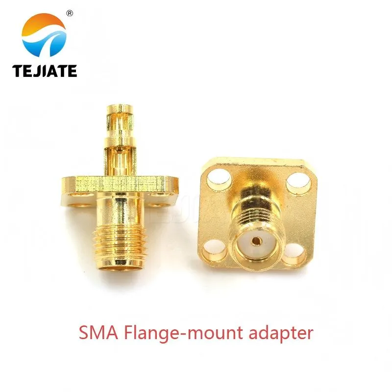
appearing during the discussion of "Torque/strain and reliability". It shows a flange-mount SMA adapter. The document points out that for outdoor gear, a flange-mount adapter with an IP67 O-ring is even better, as it adds weather sealing and mechanical relief, preventing fittings from loosening or ports from being damaged over time due to stress.

appearing during the discussion of "Torque/strain and reliability". It shows a flange-mount SMA adapter. The document points out that for outdoor gear, a flange-mount adapter with an IP67 O-ring is even better, as it adds weather sealing and mechanical relief, preventing fittings from loosening or ports from being damaged over time due to stress.
PCB keep-outs and reflow notes
When it comes to sma pcb connectors, board layout is critical. To maintain a true 50Ω transition, you’ll need to follow the manufacturer’s keep-out design around the RF launch. TEJTE’s SMA PCB series uses PTFE insulators and brass gold-plated housings, with frequency ratings up to 18 GHz, making them suitable for both prototyping and production.
A practical note: reflow soldering can stress the dielectric if your temperature profile exceeds about 260 °C. Always confirm the thermal window against the connector datasheet. One trick engineers often use is a small ground relief under the pad. It slightly reduces parasitic capacitance and improves return loss at microwave frequencies.
For reference, TEJTE’s PCB-mounted SMA connectors include footprints and solder recommendations, helping designers avoid costly signal integrity issues.
Bulkhead cutouts, O-rings, grounding
For enclosures, a bulkhead SMA male connector is the cleanest way to pass RF through a panel. TEJIATE’s SMA-KKY bulkhead series includes waterproof O-rings and locking nuts that achieve IP67 sealing.
When planning bulkhead integration, consider:
- Cutout size: most SMA bulkheads require 6.35–6.5 mm holes
- O-ring compression: enough to seal, but not so tight that it deforms the insulator
- Ground continuity: the nut and washer should make firm contact with the chassis to minimize EMI leakage
Antenna interface considerations
How can I guarantee reliability outdoors or in high-vibration setups?
Stainless vs brass: corrosion and vibration
Gold-plated brass connectors are excellent for low-loss RF, but outdoors they wear faster. Threads can tarnish or deform after months of wind, rain, or salt. That’s why TEJTE also supplies stainless steel SMA male connectors, such as the SMA-JWJ series, which are rated for ≥1000 mating cycles and proven in 48-hour salt spray tests.
If you’re selecting an sma connector for antenna deployments, stainless steel is almost always worth the investment. It resists corrosion, maintains torque under vibration, and pairs well with IP67-sealed housings for reliable long-term service.
I’ve seen marine IoT projects where brass connectors failed within a season—threads dulled, plating discolored, and the link became unstable. Switching to stainless solved the issue for years without replacement.
You can find outdoor-ready designs in TEJTE’s SMA connector catalog.
When to use a short jumper instead of rigid adapters
Another way to boost reliability is reducing mechanical stress. Mounting a heavy antenna directly on a board-mounted SMA often cracks solder joints or strains the bulkhead. Instead, insert a short sma extension cable.
A flexible jumper absorbs bending and vibration, keeping the device-side connector safe. For instance, a 15 cm RG316D jumper with molded strain relief is cheap insurance against downtime. TEJTE explains this practice in their blog: SMA Antenna Extension Cable Guide.
What specs should I submit before ordering, and how do I accept incoming parts?
Spec checklist (before order)
When preparing your BOM or RFQ, make sure you cover these basics:
- Gender & polarity: SMA male, RP-SMA male, or other variants
- Angle: straight or sma right angle connector
- Impedance: 50 Ω (default for RF) or 75 Ω for video applications
- Frequency rating: 0–6 GHz for basic use, up to 18 GHz for high-performance designs
- Material & plating: brass with gold plating, or stainless for outdoor/IP67 applications
- Electrical ratings: typical SMA males handle up to 50V RMS, 1A current, and operate in -65 °C to +165 °C environments
- Mount type: sma pcb connector, bulkhead with O-ring, flange mount, or crimp-on cable type
- Quantity & packaging: reels for production, bulk bags for prototyping
- Compliance: RoHS, REACH, and if needed, military or telecom certifications
TEJTE’s SMA connector product pages list most of these parameters, making it easier to cross-check before placing an order.
IQC Checklist — Incoming Quality Control
| Check Item | What to Verify | Tools Needed |
|---|---|---|
| Visual | Pin alignment, plating quality, O-ring intact, no thread damage | Magnifier / loupe |
| Dimensional | Overall length, thread pitch, bulkhead diameter | Calipers |
| Electrical | Continuity, insulation resistance (>5000 MΩ), quick VSWR check | Multimeter / handheld VNA |
| Mechanical | Pull test ≥20 N, torque to spec, mating cycles feel smooth | Pull tester, torque wrench |
| Environmental | Confirm datasheet claims: rated -65 °C to +165 °C, IP67 sealing for outdoor parts | Oven/cold chamber (if available) |
Typical nonconformities include off-center pins, plating flaking, or ferrule crimps with out-of-tolerance height. Document each lot number, and archive CoC or RoHS certificates for traceability.
Field note: I’ve seen batches where connectors looked fine until a simple pull test revealed ferrules slipping at just 10 N. A quick incoming check would have flagged the issue before cables went into production.
For more structured guidance, TEJTE shares inspection tips in their blog: Understanding RF Cables: The Ultimate Guide.
Frequently Asked Questions (FAQ)
How do I crimp an SMA male connector to RG316 without failing the pull test?
Crimping onto RG316 cable takes precision. If you strip too much dielectric, the pin won’t seat correctly; too little, and the braid won’t fold cleanly into the ferrule. Always use the 1.72 mm hex die recommended for RG316. After crimping, perform a pull test—look for at least 20 N of strength without slip.
Quick tip: lightly twist the braid before sliding it into the ferrule. This keeps stray strands from shorting against the pin. For a full walkthrough, see TEJTE’s guide: How to Use Crimp Connectors.
What torque should I use for brass-gold vs stainless SMA male plugs?
Brass gold-plated SMA connectors are softer; they require torque between 0.56–0.79 N·m. By contrast, stainless steel SMA male connectors can safely handle 0.90–1.13 N·m and survive more mating cycles. Over-tightening brass threads is one of the fastest ways to ruin a connector.
From experience: a torque wrench is your friend. I’ve seen connectors ruined by someone “tightening until it feels right” with pliers. For outdoor durability, TEJTE’s stainless SMA series is a solid option.
Can I mate a 50-ohm SMA male to a 75-ohm port in a pinch?
An RP-SMA male has outside threads but a female-style socket inside, while the RP-SMA female has a pin. Many people confuse it with standard SMA. The safest method is to check both the thread type and the center contact before installation.
From lab practice: labeling cables during assembly saves countless hours. Half of “mystery signal issues” I’ve seen trace back to polarity mismatches. For clarity, TEJTE offers both SMA and RP-SMA connector options.
When is a right-angle SMA male better than using a straight plug plus a bend?
Yes, mechanically it fits, but electrically it’s not recommended. A 50 ohm sma male connector on a 75Ω port increases return loss, which means wasted power and potential bit errors in digital systems. At 2.4 GHz, I’ve measured mismatched setups losing nearly 3 dB—effectively cutting the usable range in half.
If you must bridge 50Ω and 75Ω systems, use an impedance-matching adapter. TEJTE explains more about coax impedance in their RF Cable Guide.
Should I use a coupler or a short jumper between SMA male and BNC?
For low-frequency, stationary setups, a simple sma to bnc adapter works fine. But if equipment moves or the environment is harsh, a short coax jumper is far better. Jumpers absorb stress, reduce reflection loss, and protect delicate instrument ports from wear.
You’ll find practical options in TEJTE’s RF adapter cable assemblies, including SMA to BNC and SMA to N configurations.
What minimal IQC checks confirm my SMA males are in spec on arrival?
You don’t need a full RF lab to screen incoming parts. A 5-minute IQC checklist catches most problems:
- Visual: center pin alignment, plating quality, no thread damage
- Mechanical: pull strength ≥20 N, smooth mating cycles, correct torque response
- Electrical: continuity, insulation resistance ≥5000 MΩ, optional quick VSWR check
- Environmental: confirm parts rated for -65 °C to +165 °C and IP67 sealing if specified
For structured workflows, TEJTE outlines inspection practices in their blog: Understanding RF Cables: The Ultimate Guide.
Final Thoughts
Selecting the right sma male connector goes beyond matching thread size. It means confirming polarity, choosing the proper impedance, applying correct torque, and following disciplined crimping practices. With stainless or brass builds, straight or right-angle options, and IP67-rated variants, TEJTE’s catalog covers everything from lab prototypes to rugged outdoor systems.
Getting the details right—whether it’s specifying a sma crimp connector, using a short extension cable, or ordering the correct sma pcb connector—can mean the difference between a stable RF link and weeks of troubleshooting.
For engineers ready to explore product options, visit TEJTE’s SMA connector product series and check the RF blog library for deeper application notes and selection guides.
Bonfon Office Building, Longgang District, Shenzhen City, Guangdong Province, China

A China-based OEM/ODM RF communications supplier
Table of Contents
Owning your OEM/ODM/Private Label for Electronic Devices andComponents is now easier than ever.
