SMA Male Connector: Plug, Panel & PCB
Sep 21,2025
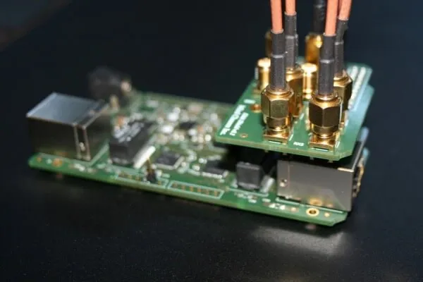
This image serves as an introductory visual aid, highlighting the critical physical attributes of a standard SMA male connector. It underscores the document's initial warning about the importance of correctly identifying the connector type (especially vs. RP-SMA) by examining its features—primarily the center pin and the 1/4"-36 threaded barrel—to avoid mating errors and potential damage.
Verify port type and polarity before choosing a male SMA
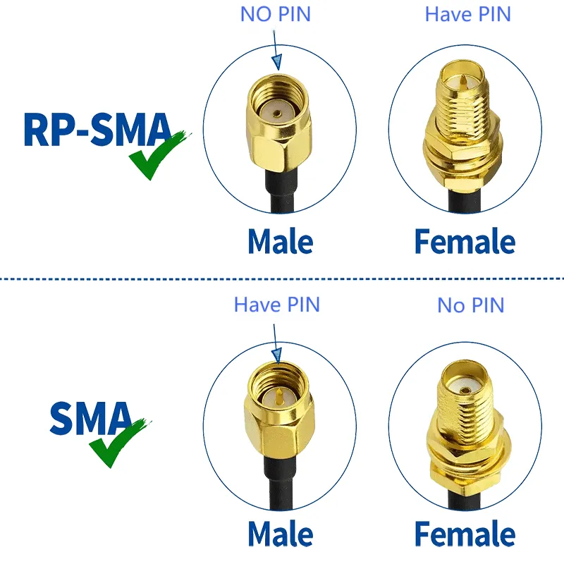
This is a crucial reference chart that clearly and simply illustrates the fundamental difference between standard SMA and Reverse Polarity SMA (RP-SMA) connectors for both male and female types. It visually demonstrates that an SMA male has a pin, while an RP-SMA male has a hole or receptacle. This directly addresses the primary point of confusion highlighted in the text, providing a quick and reliable method for engineers to avoid purchasing and mating errors.
The safest way to avoid mistakes is to cross-check part drawings or datasheets. Resources such as the RF connector families overview clarify which polarity you’re looking at. Take TEJTE’s N/SMA-KKF flange-mount type: it operates at 50 Ω impedance, covers DC–11 GHz, and maintains VSWR ≤1.2. It’s tested for 500 mating cycles from –45 °C to +125 °C, which makes it suitable for both outdoor base stations and indoor benches.
A small field habit saves a lot of rework: always inspect the center first—pin or receptacle—before confirming thread engagement. That half-minute check is faster than returning a batch of connectors.
What is an SMA male connector?
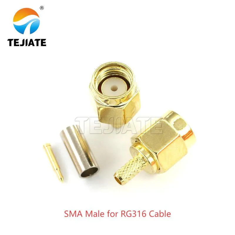
This image shows a practical example of an SMA male connector terminated onto RG316 coaxial cable. The document discusses RG316 as a popular choice for its flexibility and good high-frequency performance (attenuation ~2.34 dB/m at 6 GHz). This picture exemplifies the "cable plug" application type mentioned in the text, which is ideal for creating flexible jumpers and test leads. The context implies the importance of proper crimping techniques for such assemblies to maintain low return loss.
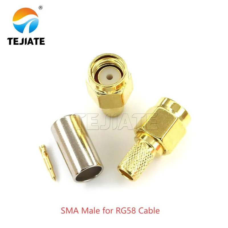
This picture displays an SMA male connector attached to RG58 coaxial cable. The text describes RG58 as having a 5 mm jacket and a high 1.8 kW peak power rating, making it suitable for applications requiring higher power handling compared to thinner cables like RG316. This image represents another variant of the "cable plug" category, highlighting the need to match the connector and crimping process to the specific cable type's dimensions and characteristics.
At its core, an sma male connector is a threaded RF plug with a pin at the center. The design ensures stable impedance and a secure fit, allowing reliable use into the microwave range. That’s why you’ll find SMA plugs on telecom gear, IoT modules, and test instruments.
Most designs use gold-plated brass contacts with a PTFE dielectric. Gold minimizes resistance and oxidation, while PTFE holds up under thermal stress. Performance numbers back it up: insertion loss stays around 0.15 dB at 6 GHz, dielectric strength reaches 1000 V RMS, and most parts last ~500 mating cycles.
Material choice also affects lifespan. Stainless housings tolerate rough handling and corrosion, while brass versions are lighter but wear sooner. TEJTE’s RF connector catalog lists SMA male options rated for DC–6 GHz or DC–11 GHz, letting engineers pick the right grade for lab instruments or high-frequency radios.
Practical tip: never force threads. If the nut doesn’t seat smoothly, stop and realign. Cross-threading destroys not just the connector but often the port it mates to.
Should you pick a cable plug, a panel/bulkhead, or a PCB mount?
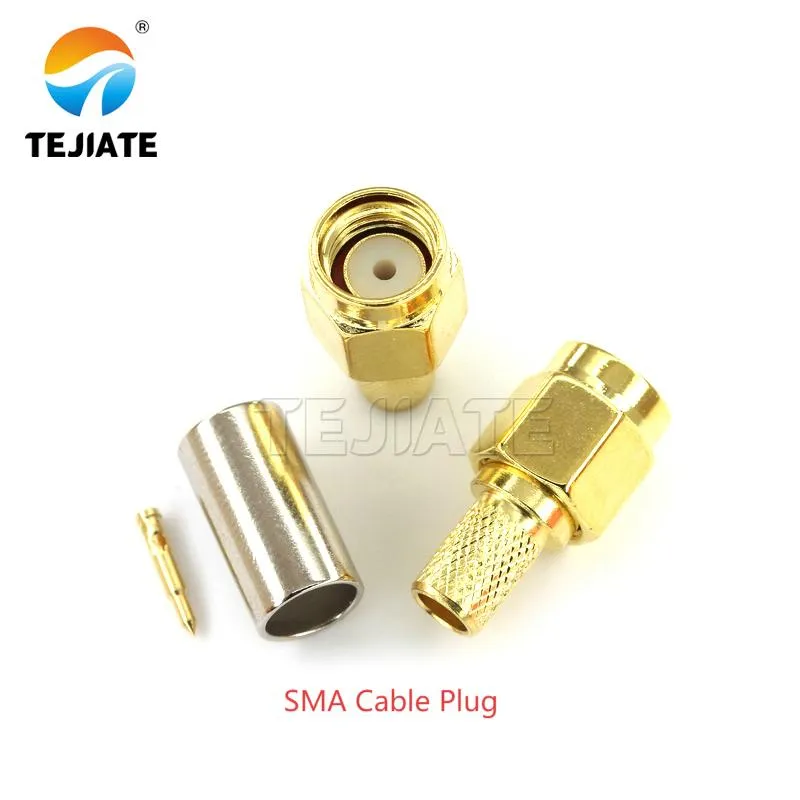
This image provides a detailed look at the components of a standard SMA male cable plug, likely including the body, pin, dielectric, ferrule, and nut. It relates to the document's extensive section on proper crimping techniques for cables like RG174, RG316, and RG58. The text emphasizes precision in strip lengths, ferrule selection, and crimp quality to avoid issues like poor return loss and unstable VSWR. This image serves as a reference for the parts involved in that critical assembly process.
- Cable plugs: Ideal when flexibility is needed. They crimp or solder onto coax like RG174 (50 Ω, 96 pF/m, cutoff ~15 GHz), RG316 (attenuation ~0.93 dB/m @1 GHz, rated to 6 GHz), or RG58 (5 mm jacket, 50 Ω, 1.8 kW peak power). Each balances different trade-offs: RG174 for compact routing, RG316 for flexibility and low loss, and RG58 for higher power. A quick tip—always measure strip lengths carefully; even a half-millimeter short can raise return loss at higher bands.
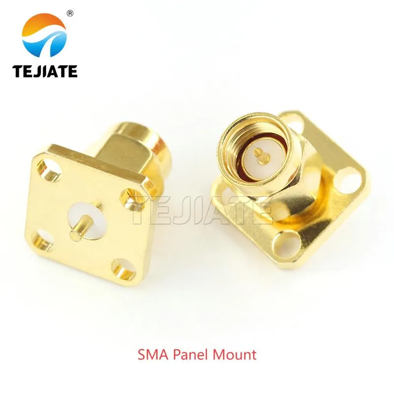
This image features an SMA male panel mount connector (or bulkhead connector). The document discusses this type as the best choice for routing cables through enclosure walls, especially when sealing is critical. It mentions features like O-ring seals and the importance of thread length to accommodate panel thickness, coatings, and washer stacks to ensure a secure and potentially waterproof fit. This picture exemplifies the connector type suited for robust, fixed installations.
- Panel or bulkhead connectors: Best for routing through enclosure walls. TEJTE’s sma panel mount connector series includes flange styles with O-ring seals and thread depths designed for coating thickness and washer stacks. This prevents the nut from bottoming out before securing properly. In outdoor gear, a good seal can be the difference between months and years of service.
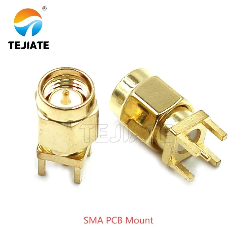
This image shows an SMA male PCB mount connector. The text describes this type as "essential for compact boards," highlighting its role in integrating RF interfaces directly into PCBs for devices like IoT modules and test equipment. It specifies series like SMA-JE-JWE, which supports 0–6 GHz and has a small 6.5 × 6.5 mm footprint. This image represents the solution for space-constrained applications where a panel mount connector would not be suitable.
- PCB-mounted SMA jacks: Essential for compact boards. The SMA-JE-JWE series supports 0–6 GHz, carries 335 V working voltage, and is available in straight or right-angle styles. With a 6.5 × 6.5 mm footprint, it’s small enough for IoT boards yet robust enough for test equipment.
In practice, if you expect frequent cable swaps, choose a crimp plug. For outdoor durability, a sma flange connector with an O-ring is safer. And for embedded RF designs, sma pcb connectors deliver the cleanest integration.
Crimp an SMA male on RG174/316/58 without return-loss issues
Crimping an sma male connector may look routine, but at RF frequencies, small errors show up fast. A poor braid fold or an oversized ferrule gap leads to poor return loss and unstable VSWR.
Take RG174 as an example. With 50 Ω impedance, 96 pF/m capacitance, and 66% velocity factor, the geometry must be exact. The ferrule bore should clear the braid by only 0.05–0.15 mm, while the pin bore must match the inner conductor within 0.05 mm. TEJTE’s internal standards require braid strip lengths at least 1.5× ferrule length to guarantee secure compression.
RG316 offers better high-frequency performance but demands more precision. It attenuates roughly 2.34 dB/m at 6 GHz, and its PTFE dielectric is unforgiving if nicked. A 1.72 mm hex die is recommended, and a pull test of ≥20 N confirms mechanical integrity. Skipping this step often leads to failures during flexing.
For RG58, with its 5 mm jacket and 1.8 kW peak power rating, ferrules are larger but the same rule applies: fold the braid cleanly, compress evenly, and inspect for stray strands. Many engineers keep a magnifier on the bench; tiny whiskers near the pin can silently kill high-frequency performance.
More preparation details can be found in TEJTE’s coaxial cable guide, which outlines strip lengths and common crimping mistakes.
How do you connect coax to a male SMA without over-torque?
Damage often comes not from bad cables but from over-tightened connectors. A sma male connector can deform threads or crack a PCB-mounted jack if forced. Leaving it too loose, though, risks poor contact and rising VSWR.
The safe range is simple: finger-tight first, then add a small wrench turn. SMA connectors are rated for 0.45–0.56 N·m torque. In labs, a calibrated torque wrench ensures accuracy; in the field, the “snug and stop” rule works reliably. Remember, the sma nut secures contact—it’s not a bolt to be cranked down.
Connector life also depends on torque. TEJTE’s RF adapter cable assemblies note that SMA jacks typically last about 500 mating cycles. Heavy torque shortens that lifespan drastically. If you’re swapping often—say in a test kit—add a short jumper cable. The jumper absorbs wear, protecting the device’s built-in port.
A quick field reminder: if you feel resistance while loosening the nut, don’t push harder. Cross-threading often masquerades as “tightness,” and forcing it guarantees a ruined port.
Do your dimensions and footprints match board and front-panel plans?
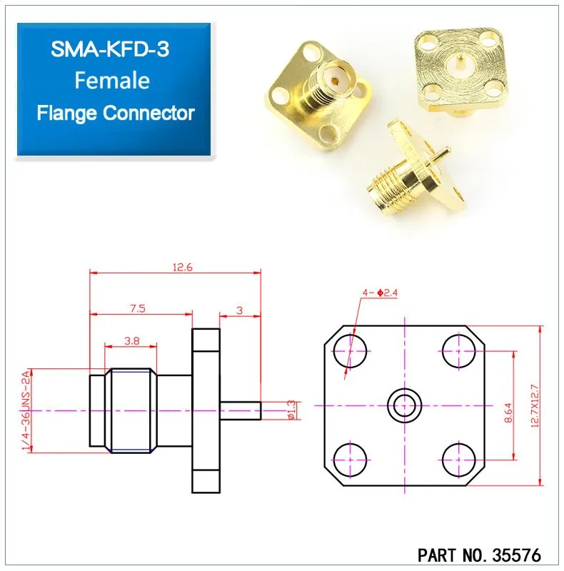
This is a detailed technical drawing for a specific SMA flange mount connector, part number 35576, identified as an SMA-KFD-3 female type. It provides precise sma connector dimensions such as hole spacing (12.7 x 12.7 mm pattern), flange size, thread specification (1/4-36 UNS-2A), and overall length. This image is central to the document's section on ensuring mechanical compatibility. It provides the concrete data needed for engineers to verify that the connector will fit their panel design, hole patterns, and accommodate any washers or seals, thus avoiding installation failures due to dimensional mismatches.
An sma panel mount connector may look correct in CAD, but unless the sma connector dimensions match your panel and gasket stack, the fit will fail. Too short a thread means the nut won’t bite; too long means the O-ring won’t seal.
TEJTE’s four-hole sma flange connector follows a 12.7*12.7 mm square pattern with 8.64 mm hole spacing. Deviating even slightly causes screws to misalign and torque to distribute unevenly. On PCBs, the SMA-JE-JWE jack requires a 6.5 × 6.5 mm footprint and 15.5 mm body length. Designers should allow at least 0.5 mm solder mask clearance and set back from the board edge to prevent cracked pads during stress.
From practical builds, many engineers 3D-print mock panels before volume runs. This catches clearance issues early, especially with washer stacks and coating thickness. TEJTE’s PCB connector guide—though focused on Ethernet—offers similar lessons: mechanical tolerances matter as much as electrical ratings.
Should the SMA male shell be chassis-grounded or isolated?
Whether the sma male connector shell bonds to chassis ground or stays isolated depends on design goals. In RF gear, the connector body often doubles as part of the shielding strategy. A flange-mounted SMA on bare aluminum gives a low-impedance ground path and strong mechanical stability.
But paint and anodizing complicate things. A coated surface insulates the joint, leaving the connector floating unless you scrape the finish or use a conductive washer. TEJTE’s waterproof bulkhead SMA connectors, featured in their panel and flange guide, address this with O-rings for sealing and optional insulating spacers for coated panels.
Isolation has its place too. Sensitive measurement systems sometimes prefer insulated shells to prevent ground loops that raise noise floors. Nylon washers or gaskets can provide the needed separation without compromising RF performance.
Field note: always confirm grounding after install. A quick continuity check with a multimeter—near-zero ohms if bonded, open if isolated—saves hours of chasing phantom EMI later. Skipping this step is one of the most common oversights in first builds.
Avoid RP-SMA vs SMA mix-ups before purchase
It’s easy to confuse an rp-sma male connector with a standard sma male connector. Both use the same 1/4″-36 thread, yet the gender of the center interface differs: the SMA male has a pin, while the RP-SMA male has a receptacle. Force-fitting them can bend contacts or damage plating.
Datasheets and catalog entries prevent mix-ups. TEJTE’s RF connector catalog clearly separates SMA from RP-SMA, listing polarity and pin details. Bulkhead drawings even show the center pin or hole, so engineers can verify before ordering.
In practice, most errors happen in bulk purchasing where “SMA” is assumed to mean all variants. A thirty-second inspection—pin versus hole—saves hours of rework. Many production lines add a simple note on storage bins: “SMA = pin / RP-SMA = hole.” That small reminder reduces costly mistakes.
Pro tip: always match polarity first, then confirm threads. Don’t let the thread fool you into assuming compatibility.
When is an N/BNC/TNC adapter or a custom jumper the better path?
An n-female to sma-male adapter can solve mismatches fast, but stacking rigid adapters isn’t ideal. Heavy N, BNC, or TNC shells act as levers, stressing the smaller SMA jack until it loosens or cracks the port.
A better solution is often a custom jumper cable. For example, RG316 offers flexibility with moderate loss, while RG58 provides higher power handling at 1.8 kW peak. Terminating one end with SMA and the other with N, BNC, or TNC spreads the load and minimizes insertion loss compared to chaining multiple adapters. TEJTE’s adapter cable assemblies cover these combinations as off-the-shelf or custom builds.
Practical guidelines:
- Use rigid adapters in static setups without vibration.
- Choose coax jumpers where the connection flexes or supports weight.
- For outdoor installs, always seal jumpers with boots or adhesive-lined heat-shrink for moisture protection.
From field installs, a jumper costs a little more up front but avoids cracked ports and callbacks later. Long term, it’s the more reliable path.
Install a 20 dB attenuator safely between male SMA and device
Protecting sensitive receivers often calls for a 20 dB sma attenuator connector placed between the device input and the incoming coax. The order of installation matters: always attach the attenuator directly to the device port first, then connect the cable. This way, torque is absorbed by the attenuator, not the fragile device jack.
Torque discipline is critical. SMA interfaces are designed for 0.45–0.56 N·m, the same range used for couplers and adapters. In labs, a torque wrench is the safest bet, but in the field the “snug and stop” method works if applied carefully. TEJTE’s SMA extension cable guide emphasizes rechecking return loss after adding inline components—attenuators included.
Heat is another concern. A 20 dB attenuator rated for 2 W continuous power can warm up quickly in sealed housings. In those cases, either add ventilation or derate the power level. Neglecting thermal load often shows up as measurement drift after long operation.
Field tip: after installation, sweep the signal chain with a VNA. Even a quick check at operating bands verifies the attenuator is seated properly and return loss hasn’t degraded. Five minutes with a network analyzer is cheaper than hours of troubleshooting.
Estimate service life and plan maintenance intervals
A well-made sma male connector is durable, but it doesn’t last forever. Most datasheets rate SMA plugs for about 500 mating cycles, though actual results depend on plating, torque habits, and exposure. Gold-plated brass contacts ensure low resistance but wear faster under heavy torque. Stainless housings survive longer but add cost and weight.
Environment accelerates wear. In salt-spray tests, standard brass connectors can corrode in under 96 hours unless properly plated. Temperature swings are another factor—TEJTE’s SMA-JE series is rated for –65 °C to +165 °C, but repeated cycling gradually fatigues the PTFE dielectric.
A simple maintenance plan prevents surprise failures. For indoor setups, inspect once a year. For outdoor base stations or IoT enclosures, check every six months. Look for rising VSWR or drifting return loss—both are early signs it’s time to replace. TEJTE’s WiFi antenna extension guide points out that in many routers, it’s the SMA port that fails before the radio module.
Pro tip: keep a usage log. Tracking connection cycles and torque checks helps predict when connectors are nearing end-of-life instead of waiting for field failures.
Size thread length and gasket stack for panel installs
Panel installs demand careful attention to sma connector dimensions. If the thread length is too short, the nut won’t grip securely. If it’s too long, the O-ring won’t compress, and sealing fails. TEJTE’s 25 × 25 mm four-hole sma flange connectors provide enough thread for standard panels, but coatings and washer stacks can change the requirement.
The solution is a simple calculation. Add up panel thickness, finish layer, washer stack, nut engagement (≥2.0 mm), and O-ring compression (10–25%). Compare this required length against the product’s specified thread. Only if the connector meets or exceeds it should the part be ordered. TEJTE’s bulkhead and flange guide shows this process in real-world enclosure builds.
Crimp & Panel Fit Dual-Checker (Info Asset Table)
| Field | Spec / Rule | Pass/Fail Criteria |
|---|---|---|
| Cable_Type | RG174 / RG316 / RG58 | Match datasheet |
| D_core | Inner conductor dia | Clearance 0.00-0.05 mm |
| D_braid | Braid outer dia. | Ferrule ID - D_braid = 0.05-0.15 mm |
| Ferrule_ID | As per spec | Within tolerance |
| Hex_Die_Size | e.g., 1.72 mm for RG316 | Must match ferrule |
| Strip_L_core / Strip_L_braid | Datasheet values | ≥1.5 × ferrule length |
| Pull_Test_Target | ≥20 N (RG316) | Pass if ≥ target |
| Panel_Thickness | Measured | Add to calc |
| Finish_Thickness | Paint/anodize | Add to calc |
| Washer_Total | Flat + insulator | Add to calc |
| Nut_Engagement | ≥2.0 mm | Required |
| O-ring_Compression | 10-25% | Required |
| Required_Thread_Length | Sum of above | ≤ Product thread length |
Torque reference for SMA, N, and BNC connectors
| Connector Type | Recommended Torque (N·m) | Notes |
|---|---|---|
| SMA male connector | 0.45 – 0.56 | Finger-tight + 1/8 turn; torque wrench for lab use |
| RP-SMA male connector | 0.45 – 0.56 | Same thread; reversed polarity – avoid confusion |
| N-type connectors | 1.35 – 1.70 | Larger threads; designed for outdoor sealing |
| BNC connectors | Hand-tight only | Bayonet lock; no torque spec |
FAQs
How do I crimp an SMA male on RG316 without hurting return loss?
Use a 1.72 mm hex die and fold the braid evenly. TEJTE’s coax prep guide recommends a pull test ≥20 N. Even a slight nick in PTFE can raise VSWR.
What torque should I use on a panel-mount SMA jack?
Stay within 0.45–0.56 N·m. The panel mount connector blog explains how proper torque protects both threads and O-rings.
Should the SMA male shell be grounded on painted panels?
Yes, but only with prep. Scrape a small area or use serrated washers. If isolation is required, use nylon spacers.
When is a coax jumper better than an N-to-SMA rigid adapter?
If the setup moves or carries weight, a jumper prevents stress. TEJTE’s adapter cable assemblies show SMA-to-N and SMA-to-BNC builds that reduce insertion loss.
How long does an SMA male connector last?
About 500 mating cycles for gold-plated brass, longer for stainless. Outdoor exposure shortens life unless plating and sealing are robust.
Key takeaways for engineers and buyers
Choosing the right sma male connector is about matching specs to application, not just ordering by name.
- Cable plugs pair well with RG174, RG316, or RG58 for test leads and jumpers.
- Sma panel mount connectors secure enclosures when sealing is critical.
- Sma pcb connectors integrate RF directly into compact boards.
Correct torqueing, grounding decisions, and life-cycle planning extend service life far beyond nominal ratings. TEJTE’s RF connector library and supporting blogs on coax, adapters, and antennas provide detailed design context that cuts down on trial and error.
Final field note: SMA connectors may look simple, but every detail counts—microns in strip length, half a turn of torque, or a washer stack can decide whether your system runs clean or fails early. By checking polarity, sizing dimensions, and following sound crimping practices, engineers keep connections reliable from lab benches to 5G deployments.
Bonfon Office Building, Longgang District, Shenzhen City, Guangdong Province, China

A China-based OEM/ODM RF communications supplier
Table of Contents
Owning your OEM/ODM/Private Label for Electronic Devices andComponents is now easier than ever.
