SMA Female Connector: Panel, Flange & PCB Mount
Sep 21,2025
Introduction
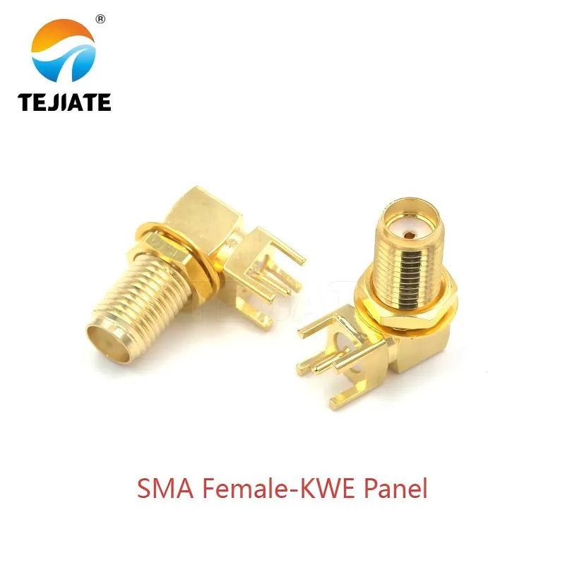
This image introduces a standard SMA panel mount connector, specifically the KWE style. It features a threaded barrel that passes through a hole in the panel and is secured from the outside with a nut. This type of connector is fundamental for creating a robust and stable RF interface on equipment enclosures, as discussed in the document's introduction about choosing the right mount type for your application.
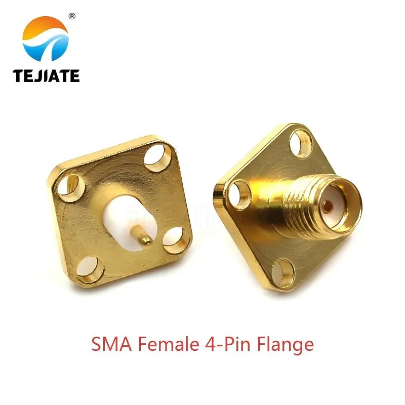
This picture showcases an SMA flange mount connector, identified by its four mounting holes. As the document explains, this design spreads mechanical stress across the panel, making it highly resistant to vibration and torque—a common requirement in telecom and networking equipment. The text specifies the SMA-KKF model with an 18mm length and mentions testing to standards like MIL-STD-202, highlighting its robustness.
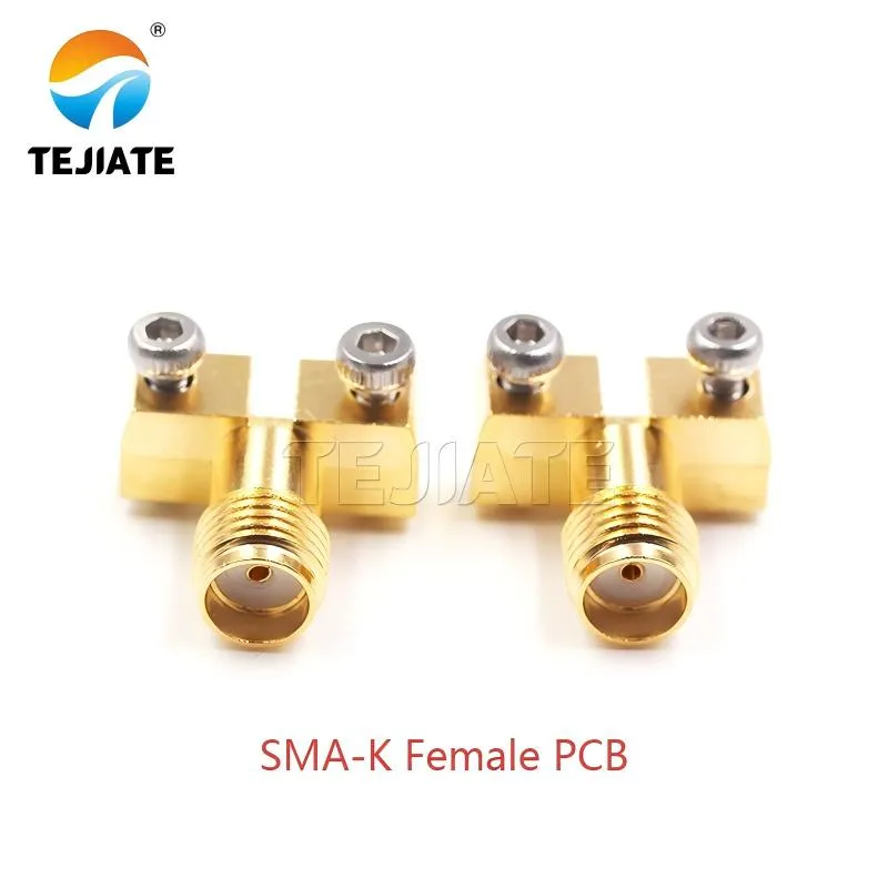
This image depicts a PCB-mount SMA female connector. The document emphasizes the advantages of this type: its compact size, cost-effectiveness, and the fact that soldering it directly to the board keeps the RF signal path short, which is crucial for minimizing return loss in space-constrained devices like IoT modules and compact RF boards.
In RF design, small details often carry big consequences. One such detail is the sma female connector—choose the wrong one and you may spend days troubleshooting return-loss or stability issues. Select the right type, and the signal chain tends to stay solid across its rated band.
Within TEJIATE’s portfolio, you’ll find sma panel mount connectors, flange-mount options, and PCB-mount jacks, each tuned for different applications. Brass, gold-plated models handle frequencies up to 6 GHz with flexible coax, while semi-rigid compatible versions extend performance all the way to 18 GHz.
A common example: most Wi-Fi routers use a bulkhead sma female connector with an O-ring seal, because dust and moisture would otherwise creep inside. In contrast, an IoT board usually benefits from a compact PCB-mount sma jack, soldered directly to minimize signal path length and keep losses low.
A quick tip from field installs: always match connector type to both your enclosure and your long-term maintenance plan. Swapping a panel-mount for a PCB-mount later often means redesigning housings, which is a cost no engineer wants to justify after production.
Verify port type and polarity before choosing an SMA female
Before ordering, take a moment to double-check whether the port you’re dealing with is truly an sma female connector or an rp-sma female connector. At first glance, both share the same internal threads, but the center contact makes all the difference. The sma female has a socket, while the rp-sma female connector has a center pin. They’ll screw together smoothly, yet the signal won’t pass if the polarity is mismatched. Many engineers have faced this problem when swapping antennas, only to find nothing works.
Another source of confusion lies in naming. In RF terminology, “jack” refers to female and “plug” refers to male. So if a datasheet calls something an sma jack, it’s simply another way of saying sma female connector. Overlooking this detail often leads to ordering the wrong part and unnecessary project delays.
A quick, practical tip: keep one correctly labeled sma connector and rp-sma connector in your toolkit as reference samples. When in doubt, comparing against a known part is faster and more reliable than guessing, especially when time is tight on site.
What is an SMA female connector?
An sma female connector is a 50-ohm RF interface built with 1/4″-36 UNS-2A threads. It mates with an SMA male plug to create a stable, low-loss connection that’s widely used across RF and wireless systems. At first glance, it looks like a simple threaded part with a dielectric insert, but every dimension and material choice is designed to balance strength, impedance control, and long-term reliability.
TEJIATE’s product line shows why these connectors remain so popular:
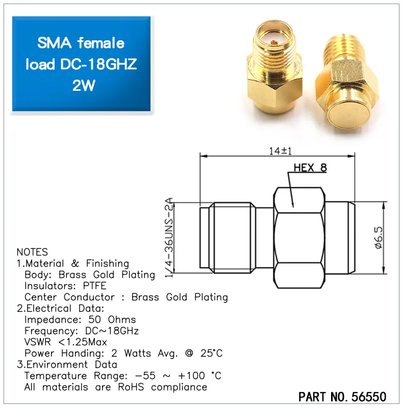
This is a detailed technical specification sheet for a specific SMA female connector (Part No. 56550). It provides crucial information highlighted in the document: materials (Brass, Gold Plating, PTFE), key electrical data (Impedance: 50 Ohms, Frequency: DC-18GHz, VSWR <1.25, Power: 2W), mechanical dimensions (Hex size, Thread type: 1/4-36UNS-2A), and environmental ratings (Temperature: -55 ~ +100 °C, RoHS). This image serves as a concrete example of the precision engineering and performance metrics discussed.
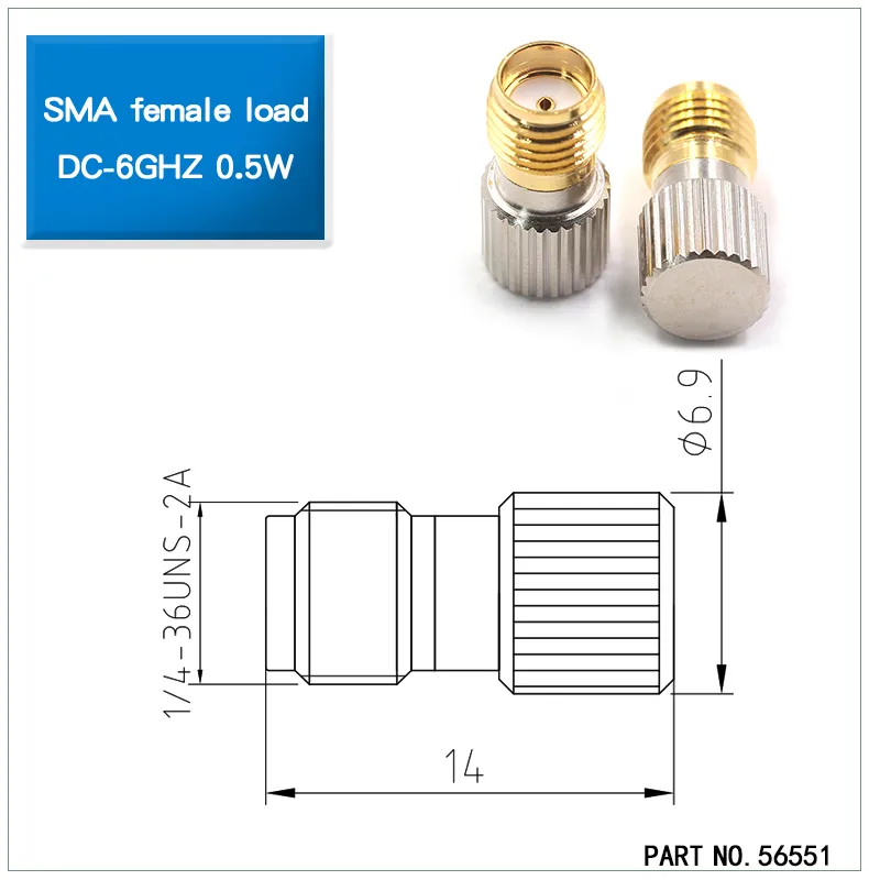
This image shows an SMA female load (Part No. 64278), which is a type of terminator. While not a connector for cables, it mates with an SMA male port to provide a matched 50-ohm load, absorbing RF power and minimizing reflections. The specs listed on the image (20dB attenuation, DC-6GHz, 2W power handling) align with the document's context of ensuring proper termination and preventing damage to equipment, as mentioned in the tip about using attenuators.
- Working frequency: up to 6 GHz for standard flexible coax, and as high as 18 GHz with semi-rigid cable assemblies.
- Voltage rating: 335 V RMS, with RoHS-compliant materials.
- Insulation: PTFE, rated for −65 °C to +165 °C, stable even under thermal cycling.
- Durability: tested for ≥500 mating cycles, and insertion loss kept below 0.15 dB at 6 GHz.
For engineers, this means that whether you’re building a smart home hub, an SDR test board, or a compact small-cell station, the sma female connector provides the mechanical strength and RF performance needed for clean transmission.
Quick field note: after several hundred cycles, it’s good practice to check VSWR and contact resistance. A part that still threads smoothly might already show higher return loss—swapping it early can save hours of troubleshooting later.
Should you use panel-mount, flange, or PCB-mount for your enclosure?
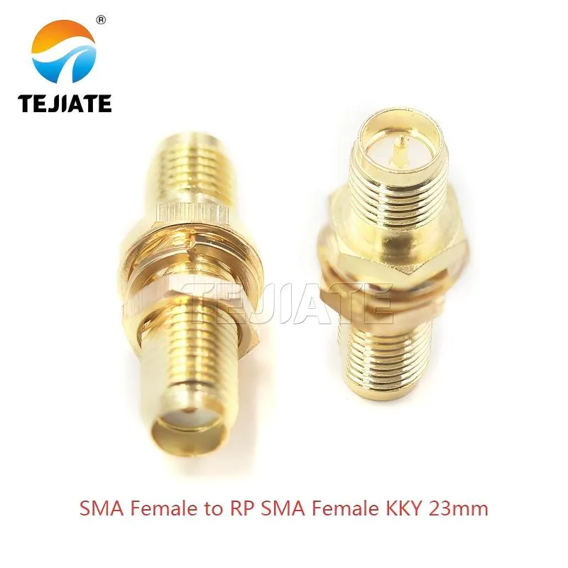
This image displays a specific adapter: an SMA female to RP-SMA female coupler, identified as model KKY with a 23mm length. This type of adapter is crucial for resolving polarity mismatches. It allows a cable with a standard SMA male connector (which has a pin) to connect to a cable with an RP-SMA male connector (which has a hole), by providing the correct female interfaces (socket for SMA, pin for RP-SMA) on each end. The document discusses the importance of understanding and adapting to different polarities (SMA vs. RP-SMA).
- SMA panel mount connectors are the classic choice when the jack needs to pass through a metal housing. TEJIATE’s SMA-KKY bulkhead (around 23 mm total length) includes an O-ring that keeps dust and moisture out. Once tightened, the nut holds steady, even when the connector is frequently connected and disconnected.
- Flange-mount SMA connectors shine where vibration or torque is a concern. The SMA-KKF four-hole flange design (18 mm length) spreads stress across the panel, making it reliable for telecom and networking equipment. Tested under standards such as MIL-STD-202 vibration method, this option offers extra security.
- PCB-mount sma female connectors are compact and cost-effective. Soldered directly onto the board, they keep the RF path short, which helps reduce return loss. They’re widely used in IoT modules and compact RF devices where space is tight.
A quick engineer’s tip: don’t overlook coatings. A layer of paint or anodizing on the panel may seem thin, but it can prevent the sma nut from fully engaging. In those cases, it’s often safer to go with a long-thread bulkhead or switch to a flange-mount style to ensure proper fastening.
For more examples and drawings, you can explore TEJTE’s SMA bulkhead connector guide, which compares mounting options in real-world setups.
Crimp an SMA female correctly to avoid return-loss issues
Even a top-grade sma female connector can’t perform to spec if the crimping is sloppy. On paper, it may promise VSWR ≤1.10 up to 10 GHz, but a bad termination will quickly ruin that. Return loss climbs, and the signal chain starts to misbehave.
Here’s what experienced installers pay close attention to:
- Strip dimensions: For TEJIATE’s SMA-KKY bulkhead, leave about 4 mm of PTFE dielectric and 3 mm of exposed copper conductor. A rushed strip often means uneven cuts or nicked braids.
- Slide the ferrule first: It sounds obvious, yet it’s one of the most common mistakes. Forget it once, and you’ll be cutting and prepping the cable all over again.
- Use the correct die size: Too loose, and the braid won’t hold; too tight, and the dielectric collapses. Either way, impedance is off.
- Inspect carefully: Under magnification, a single folded braid strand can push VSWR from 1.05 to 1.20.
Many field engineers compare crimping to plumbing: if the joint isn’t sealed right, expect leaks. In RF work, that “leak” shows up as higher insertion loss. Done correctly, TEJIATE connectors regularly achieve insertion loss below 0.15 dB at 6 GHz.
Quick tip: after every crimp, run a return-loss check if possible. It’s far easier to rework a connector at the bench than to chase down weak signals in the field later.
Connect coax to an SMA female port without damaging the jack
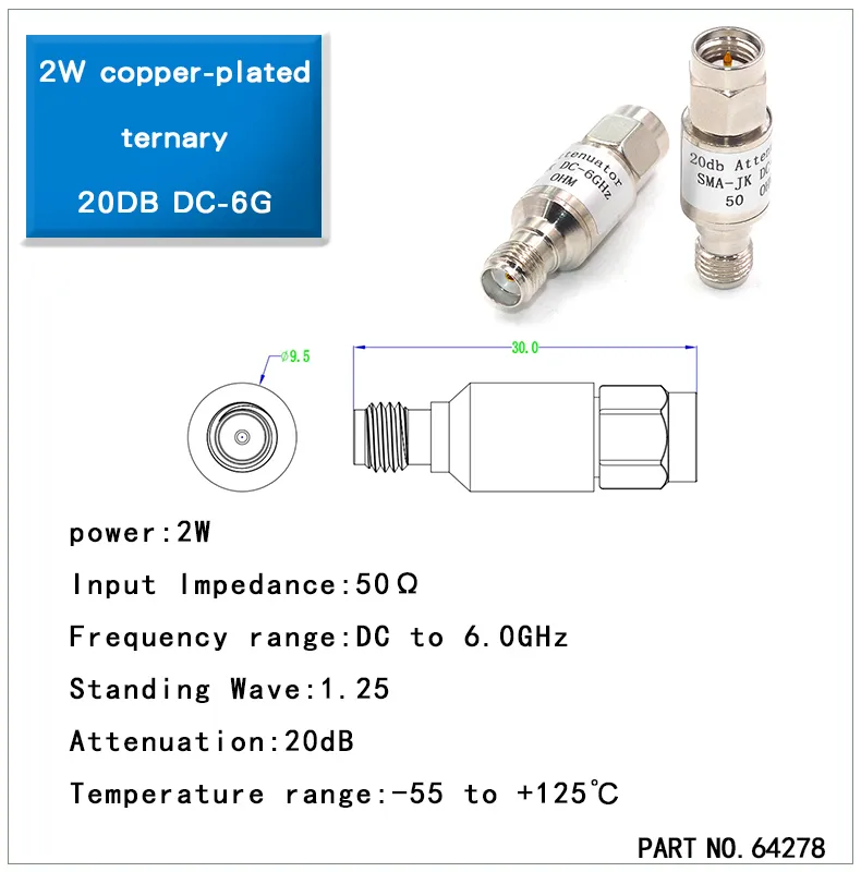
This image features an SMA attenuator (Part No. 64278) with a female input port, rated for 20dB of attenuation and 2W of power. The document mentions using such accessories—specifically inserting a 20 dB attenuator before a sensitive instrument port—as a protective measure. It highlights the practical tip that damaging a cheap attenuator is preferable to damaging the expensive SMA female connector on the analyzer itself. This image exemplifies a common tool for power management and equipment protection in RF systems.
At first glance, attaching a coax cable to an sma female connector feels straightforward. But in practice, this is where many ports get damaged. The SMA interface is built for precision; even a small misstep can shorten the life of a connector rated for ≥500 mating cycles.
A few habits help avoid costly mistakes:
- Start by hand: Always thread the coax nut onto the sma jack by hand first. The 1/4″-36 UNS-2A threads are fine-pitched, and forcing them risks cross-threading. One bad twist can scrap a panel connector.
- Apply the right torque: For critical assemblies, tighten with a torque wrench to about 0.45 N·m (4 in-lbs). Too much torque crushes the PTFE dielectric; too little leaves the ground path loose.
- Rotate the nut, not the cable: Spinning the coax body twists the braid inside and eventually weakens the crimp.
In lab environments, engineers often use a short “port saver jumper.” Instead of plugging directly into an analyzer’s sma female bulkhead connector, the jumper takes the wear. It’s a cheap sacrificial part compared to repairing a damaged instrument port.
Field tip: if you’re inserting accessories—say a 20 dB attenuator—always confirm its power rating before use. Losing a $30 adapter is inconvenient, but damaging the main connector can put equipment out of service.
For more practical guidance and jumper options, check TEJTE’s RF adapter cable section.
Do dimensions and footprints meet your board and front-panel plan?
Choosing the right sma female connector isn’t only about bandwidth or impedance—it also has to fit the physical design. If the sma connector dimensions don’t line up with your board layout or panel stack, you’ll end up fighting mechanical stress, weak fastening, or worse, failed assembly during production.
Engineers typically check a few key points:
- Panel cutout: Bulkhead models like TEJIATE’s SMA-KKY (23 mm overall length) need a hole size of around 6.3–6.5 mm. Too tight, and you risk damaging the panel finish; too loose, and the O-ring seal won’t hold.
- Nut engagement: Always leave clearance for the sma nut plus washers. TEJIATE datasheets recommend at least one full nut thickness of bite to ensure stability.
- Flange spacing: Four-hole types such as the SMA-KKF follow a 12.7 × 8.6 mm pattern, spreading torque and keeping the connector from rotating under vibration.
- PCB footprints: Through-hole designs benefit from reinforced pads, while SMT footprints must align precisely with the RF trace. Even a small offset can nudge return loss higher than expected.
Material also matters. A brass gold-plated sma jack resists corrosion indoors, but for rugged or vibration-heavy use, a stainless steel sma connector extends service life to 1000 cycles or more.
Practical tip: never overlook paint or anodizing thickness on the panel. More than one engineer has discovered too late that the sma panel mount connector wouldn’t seat properly because the coating added just enough thickness to block full nut engagement.
For clearance drawings and real-world mounting advice, see TEJTE’s SMA bulkhead connector guide.
Waterproof an SMA female bulkhead for outdoor installs
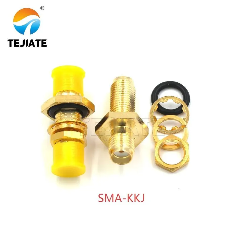
This picture shows a waterproof SMA bulkhead connector, model KKJ. It is presented in the document's section dedicated to outdoor installations. The text emphasizes that standard connectors are insufficient outdoors and that designs like this, which include sealing features (e.g., silicone O-rings), are necessary to prevent moisture ingress, which leads to corrosion and increased return loss. This connector is suited for applications like 4G/5G CPE, surveillance cameras, and wireless bridges.
When RF equipment is deployed outdoors—whether it’s a 4G/5G CPE, a surveillance camera, or a wireless bridge—a standard connector often isn’t enough. An sma bulkhead connector without sealing can let moisture in, which corrodes contacts and increases return loss over time. That’s why many TEJIATE designs include silicone O-rings and compression hardware to keep things watertight.
Here are a few points to watch:
- Seal with O-rings: A model such as the SMA-KKY bulkhead with waterproof ring compresses against the panel to create an IP67-rated barrier. That keeps dust and water out while maintaining insertion loss ≤0.15 dB at 6 GHz.
- Account for coating thickness: Painted or anodized panels reduce usable thread length. With a connector rated at 23 mm thread length, check that the sma nut still engages securely once coatings, washers, and O-rings are stacked.
- Prevent galvanic corrosion: Mounting a brass, gold-plated sma female connector directly in an aluminum housing can trigger galvanic reaction. A thin insulating washer is an easy fix that extends service life.
Practical tip: don’t overtighten when compressing the O-ring. Too much torque can crush it flat, while too little leaves gaps. Field engineers often carry a few spare O-rings—cheap insurance against downtime in harsh environments.
For rugged designs and outdoor-ready options, check TEJTE’s RF connectors catalog, which includes waterproof sma female connectors as well as flange-mount versions for demanding environments.
When should you use an adapter to reach N/BNC/TNC from an SMA female?
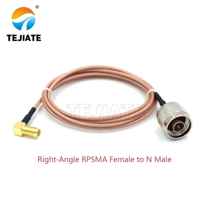
This image illustrates a specialized right-angle adapter that combines two functions: 1) changing the connector interface from RP-SMA to the larger N-type, and 2) providing a 90-degree elbow for mechanical relief. The document discusses using adapters to bridge between different connector families (SMA to N, BNC, TNC). This particular adapter would be used to connect a device with an RP-SMA female port (like some WiFi routers) to an N-type cable or antenna, while also saving space and reducing strain thanks to its right-angle design.
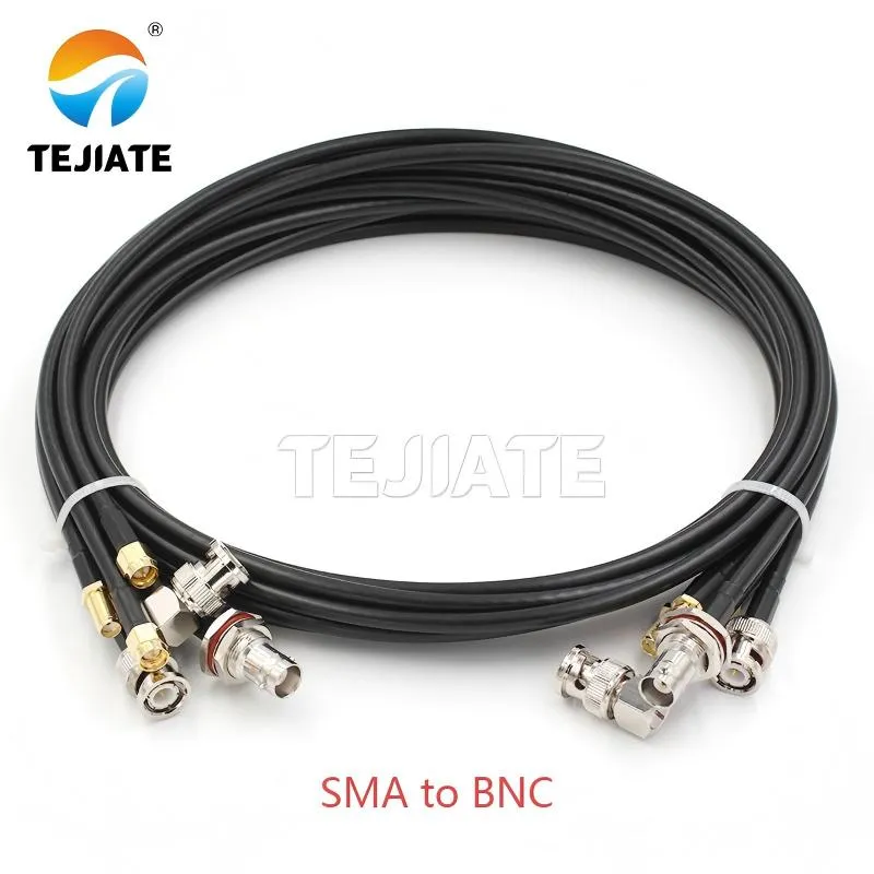
This image shows a fundamental interface adapter: SMA female to BNC male. The document discusses the use of such adapters for occasional connections, e.g., linking an SMA test port to a BNC cable. It presents this as a quick and affordable solution but also cautions that for permanent or frequent setups, a flexible jumper cable is often a better choice to reduce strain on the ports and avoid the extra VSWR from stacking rigid adapters. This image represents a staple tool in many RF toolkits for basic connectivity needs.
Sooner or later, you’ll need to connect an sma female connector to another standard like N, BNC, or TNC. The obvious fix is an adapter, but the smarter choice depends on how often and how critical the connection is.
- Direct adapter: If you only connect occasionally—for example, linking an SMA test port to a BNC cable—then an SMA-to-BNC adapter is fine. It’s quick, affordable, and available almost anywhere.
- Short jumper cable: For permanent or frequent setups, a flexible SMA-to-N or SMA-to-TNC coax jumper is usually better. It reduces strain on the sma jack, keeps impedance matched, and avoids the extra VSWR that comes with stacking rigid adapters.
- Local sourcing vs. custom build: Sure, you can grab an N-female to SMA-male adapter at a local electronics store. But for gear that runs continuously, a custom jumper with verified specs will hold up longer and save headaches down the line.
Practical tip: avoid stacking multiple rigid adapters on a panel-mount sma bulkhead connector. The extra leverage can loosen the nut or twist the panel over time. A simple jumper is cheaper than a field repair.
For adapter and jumper solutions, TEJTE’s RF adapter cable range covers SMA-to-N, SMA-to-BNC, and SMA-to-TNC assemblies, designed for both lab benches and outdoor deployments.
Estimate connector life and plan maintenance intervals
Every sma female connector has a service life. TEJIATE’s brass, gold-plated versions are typically rated for ≥500 mating cycles, while stainless steel designs can go up to 1000 cycles under controlled conditions. After that point, wear on the threads or center socket usually shows up as higher insertion loss or unstable return loss.
A few factors shorten lifespan:
- Over-torquing: Tightening beyond 0.45 N·m (4 in-lbs) compresses the PTFE dielectric and stresses the threads.
- Outdoor exposure: Humidity, salt, and temperature swings speed up corrosion, especially on bulkhead connectors.
- Frequent swaps: In labs where cables are changed daily, connectors can wear out within a year even if the spec says 500+ cycles.
Engineers often rotate between spare ports to spread wear. Another common strategy is to use a port saver jumper, so the jumper absorbs the wear and the instrument’s front-panel sma jack stays intact.
Practical tip: don’t just track the number of connections—measure performance over time. Rising contact resistance (above 5 mΩ for inner conductor or 2 mΩ for outer) is often the first sign it’s time to replace.
For more advice on extending connector life and protecting ports, see TEJTE’s SMA extension cable guide.
Size thread length for panel stacks before checkout
One of the easiest mistakes to make when using an sma bulkhead connector is overlooking how much thread length gets consumed once coatings, washers, and O-rings are stacked together. If the sma nut can’t bite deeply enough, the connector may feel loose, and over time vibration will make it worse.
A quick calculation helps avoid that:
| Field | Example Value | What it tells you |
|---|---|---|
| Panel_Thickness (mm) | 1.5 mm | Bare aluminum panel |
| Finish_Thickness (mm) | 0.1 mm | Powder-coating layer |
| Washer_Total (mm) | 1.0 mm | Flat + spring washer stack |
| Nut_Engagement (mm) | 1.5 mm | Minimum safe thread bite |
| O-ring_Compression (mm) | 0.6 mm | 10–25 % typical seal compression |
| Product_Thread_Length (mm) | 23 mm | TEJIATE SMA-KKY bulkhead |
| Required_Thread_Length | 4.7 mm | Combined stack-up |
Pass/Fail check:
- If Required_Thread_Length ≤ Product_Thread_Length, the installation is safe.
- If it fails, upgrade to a long-thread bulkhead or switch to a flange-mount sma connector that fastens with screws.
Example: a 2 mm painted panel plus washers and gasket can push the requirement beyond 5 mm. TEJIATE’s SMA-KKY bulkhead (23 mm thread length) still passes easily, but a shorter bulkhead would fail.
This simple check, done before checkout, saves rework in the field and ensures long-term stability. For detailed drawings and more mounting guidance, see TEJTE’s SMA bulkhead connector blog.
Frequently Asked Questions (FAQ)
How do I crimp an SMA female connector without degrading return loss?
What panel-mount or flange option should I pick for a painted aluminum enclosure?
How do I connect coax to an SMA female jack while avoiding over-torque?
When should I use a feedthrough plus a short jumper instead of a rigid coupler?
Where can I source an N-female to SMA-male adapter locally, and is a custom jumper better?
Can I inline a 20 dB SMA attenuator between my device and an SMA female port safely?
Bonfon Office Building, Longgang District, Shenzhen City, Guangdong Province, China

A China-based OEM/ODM RF communications supplier
Table of Contents
Owning your OEM/ODM/Private Label for Electronic Devices andComponents is now easier than ever.
