U.FL to SMA Cable Guide – Types, Length, Loss & Mounting Tips
Sep 09,2025
1) Introduction
In many wireless designs, the challenge isn’t the chip or the antenna—it’s getting the signal out of the enclosure. That’s where a U.FL to SMA cable comes in. By linking the delicate on-board U.FL/IPX port to a rugged SMA bulkhead on the housing, you can mount antennas exactly where they work best. This approach is common across Wi-Fi and Bluetooth modules, LTE/5G CPEs, GPS receivers, and IoT gateways that sit inside metal cases.
What readers gain here is clarity: how MHF1 (U.FL) differs from MHF4, why coax diameter and length dictate signal loss, and which SMA vs RP-SMA orientation suits each scenario. We’ll also cover bulkhead threads, waterproof sealing, and a quick selection checklist that helps avoid mismatches.
For engineers who want more context on coaxial basics, the NIST RF measurement guidelines provide a solid foundation on impedance and attenuation behavior.
2) What Is a U.FL/IPX to SMA Cable?
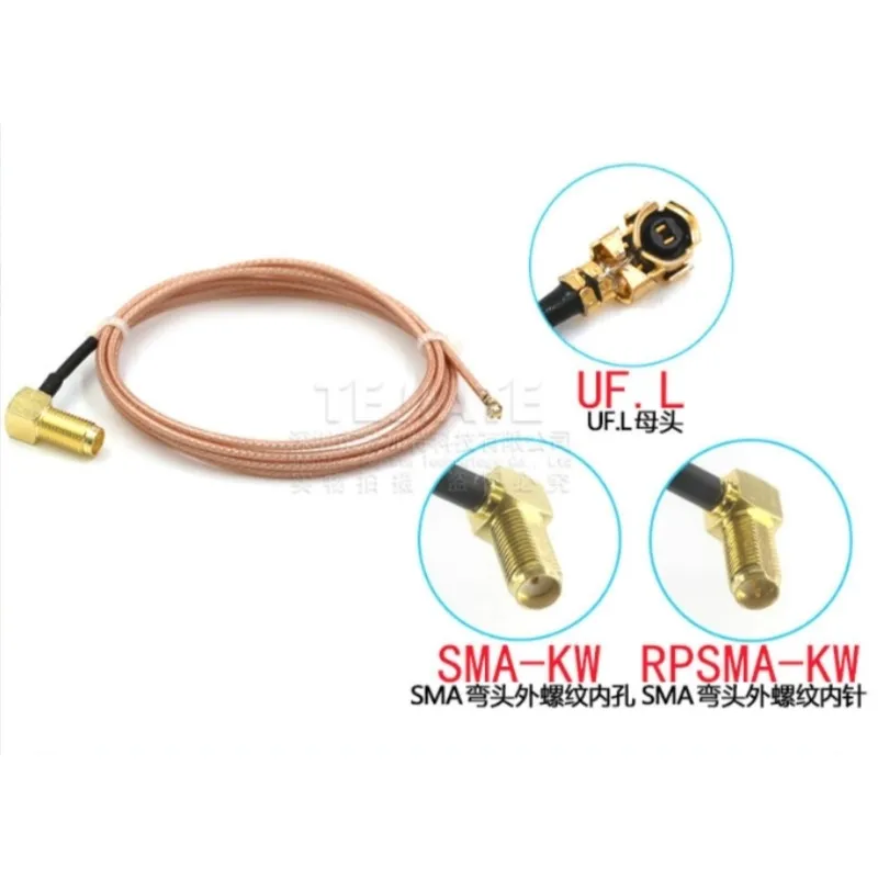
This image illustrates the physical structure of a U.FL to SMA cable, highlighting the miniature U.FL connector on one end and the standard SMA connector on the other. It is used to bridge internal RF modules to external antennas.
A U.FL/IPX to SMA cable is not a converter in the digital sense. It doesn’t alter protocols or signals—it simply provides a mechanical and electrical bridge for RF energy. One end terminates in a micro coax snap connector, typically U.FL (MHF1) or the newer MHF4. The opposite end features an SMA or RP-SMA jack, often designed for panel mounting with a nut, washer, and O-ring.
Typical constructions use 50-ohm micro coax such as RF1.13, RF1.37, or RF0.81 mm. For example, RF1.13 has an outer diameter of about 1.13 mm with attenuation ~0.8 dB/10 cm at 2.4 GHz and ~1.2 dB/10 cm at 5.8 GHz, making it ideal for short jumpers on Wi-Fi or GPS modules. RF0.81, being slimmer, offers maximum flexibility but incurs higher loss—~1.2 dB at 2.4 GHz and ~1.9 dB at 5.8 GHz per 10 cm.
In practice, this assembly shows up on mini-PCIe or M.2 wireless cards, connecting internal ports to antennas on router housings. For a practical example, see our detailed breakdown in Understanding RF Cables, where similar micro coax families are compared.
3) Generations & Compatibility: MHF1 (U.FL) vs MHF4
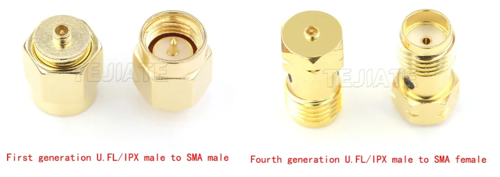
This image shows the physical differences between MHF1 (U.FL) and MHF4 connectors, including height and locking mechanism, to help users avoid compatibility issues during assembly.
Not every connector labeled “IPEX” is interchangeable. The original MHF1/U.FL became the de facto choice on Wi-Fi modules using mini-PCIe, while the newer MHF4 shrank the footprint and tightened snap force—making it the go-to for LTE/5G and GPS modules on M.2 (NGFF) cards.
The differences are subtle yet important. MHF1 sits around 2.5 mm tall, while MHF4 drops to roughly 1.2 mm. Push the wrong type into a socket, and you risk cracking the PCB pad. The safest move is simple: check your module’s datasheet first. From experience, engineers often keep both types in stock during prototyping just to avoid unnecessary downtime.
To give you a clearer picture, here’s a quick comparison across generations:
| Feature | MHF1 (U.FL / IPEX) | MHF4 (4th-gen) | MHF5 (newer gen) |
|---|---|---|---|
| Typical height | ~2.5 mm | ~1.2 mm | ~1.0 mm |
| Common interface | Mini-PCIe Wi-Fi | M.2 LTE/5G, GPS | Specialized IoT |
| Snap force | Moderate | Higher retention | Similar to MHF4 |
| Durability | ~30-50 cycles | ~30 cycles | ~30 cycles |
| Risk if mismatched | Loose fit / signal drop | Socket damage / pad lift | Not widely interchangeable |
4) Coax Choices: 1.13 vs 1.37 vs 1.78 vs 0.81
| Cable Type | Diameter (mm) | Attenuation @2.4 GHz (dB/10 cm) | Attenuation @5.8 GHz (dB/10 cm) | Flexibility | Typical Use |
|---|---|---|---|---|---|
| RF0.81 | 0.81 | ~1.2 | ~1.9 | ★★★★★ | Ultra-compact IoT, wearables |
| RF1.13 | 1.13 | ~0.8 | ~1.2 | ★★★★ | Wi-Fi cards, GPS jumpers |
| RF1.37 | 1.37 | ~0.6 | ~1.0 | ★★★ | LTE/5G CPE, routers |
| RG178 | 1.8 | ~0.5 | ~0.9 | ★★★ | Industrial, outdoor antennas |
5) SMA Side Options: Gender/Polarity & Orientation
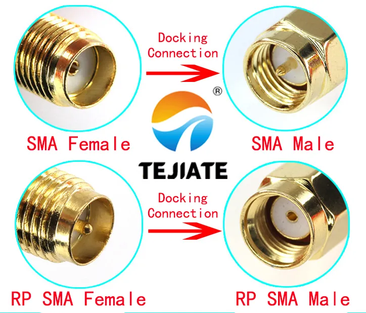
This image clarifies the differences between standard SMA and reverse polarity (RP-SMA) connectors, including gender and pin configuration, to ensure correct mating in RF systems.
On the SMA side, the main questions are gender and polarity. A standard SMA male has an inside pin and external threads, while a SMA female has an inner socket and internal threads. The RP-SMA (reverse polarity) versions swap the pin/no-pin configuration. Many consumer routers use RP-SMA female jacks, so the right match is usually a U.FL to RP-SMA male pigtail.
Orientation also matters. Straight SMA bulkheads (e.g., SMA-KE) are compact and simple to install, while right-angle SMA types (SMA-KWE) reduce strain in tight enclosures. Specs from real parts show both operate across DC–6 GHz with VSWR straight ≤1.05+0.002f and VSWR right-angle ≤1.20+0.003f. That means the right-angle introduces slightly higher mismatch at 5 GHz, but often the mechanical relief is worth it.
For further reading, see What Is SMA Connector (Male/Female, Jack)?, where we discuss polarity and mechanical design in detail. The IEEE Microwave Theory and Techniques Society has also published work confirming that SMA and RP-SMA mis-mating can cause up to 1–2 dB extra insertion loss—an expensive mistake in high-frequency designs.
6) Mounting: Bulkhead Threads, Flanges & Waterproof
The last step is securing the SMA connector to the housing. The bulkhead SMA is the most common, with thread lengths available in 8, 11, 13, and 15 mm. Selecting the right one depends on panel thickness plus the added space for washer, nut, and O-ring compression. For instance, a 2 mm aluminum panel with sealing hardware typically needs ≥13 mm thread to seat properly.
For outdoor or rugged setups, sealing is crucial. SMA connectors with silicone rubber O-rings and Teflon insulators can handle insertion loss ≤0.15 dB at 6 GHz and withstand 500+ mating cycles. In industrial telecom equipment, flange-mount SMA (2-hole or 4-hole) designs are often preferred. They resist torque and vibration better than bulkheads—a fact also noted in NASA RF connector guidelines.
| Mount Style | Thread Length | Orientation | Seal Type | Typical Use |
|---|---|---|---|---|
| Bulkhead standard | 8–15 mm | Straight | O-ring optional | Router/AP housings |
| Bulkhead standard | 11–15 mm | Right-angle | O-ring optional | IoT gateways, CPEs |
| Flange 2-hole | — | Straight | O-ring standard | Industrial routers |
| Flange 4-hole | — | Straight | O-ring standard | Outdoor telecom base stations |
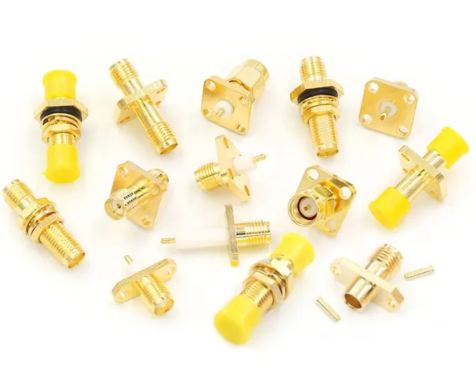
This image displays common mounting options for SMA connectors, including threaded bulkhead and flange styles, used in routers, gateways, and outdoor equipment.
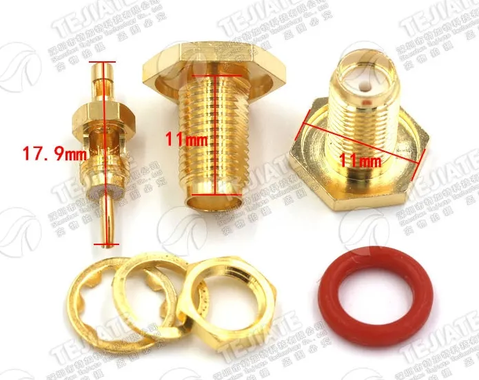
This image highlights the sealing features of a waterproof SMA connector, including the O-ring and Teflon insulator, designed for harsh environmental conditions.
7) Length Planning & Loss
Cable length is often underestimated, yet it directly impacts signal quality. The rule of thumb is simple: keep it as short as possible. At 2.4 GHz, a 10 cm RF1.13 cable typically shows ~0.8 dB insertion loss. Stretch that to 20 cm and the figure nearly doubles. At 5.8 GHz, the penalty is even harsher—~1.2 dB at 10 cm grows to over 2 dB at 20 cm.
Standard assemblies are available in 10 cm, 15 cm, 20 cm, 50 cm, and 1 m lengths, with custom builds up to 2 m. For 5G sub-6 applications or GPS modules, staying under 30 cm with RF1.13 or RF1.37 keeps performance reliable. Longer lengths should use RG178 or other lower-loss cables. According to the IEEE Communications Society, every extra dB of attenuation at higher frequencies can reduce link margin enough to cause dropped connections in dense wireless environments.
For real-world planning, many engineers rely on short U.FL to RP-SMA pigtails to connect a PCB to a chassis antenna port, then extend with standard SMA cables outside. This approach minimizes fragile micro coax runs while still allowing antenna flexibility. More details are available in our RF Cable Guide.
8) Use Cases
The U.FL to SMA cable assembly shows up in almost every corner of wireless design. In Wi-Fi gear, it often works as a wifi antenna cable, moving the RF path from a tiny board connector to an external antenna. That’s especially true for consumer and enterprise gear, where a short jumper doubles as a router antenna cable—simple, reliable, and easy to swap when antennas change.
Navigation is another big area. Engineers commonly rely on these jumpers as gps antenna cable links, bridging delicate GNSS modules to roof-mounted SMA antennas in vehicles or outdoor enclosures. If you’ve ever noticed a GPS unit keeping signal lock while tucked inside a car, chances are there’s a coax like this hidden behind the panel.
For cellular gear, an ipex to sma cable is the standard bridge in LTE/5G CPEs and IoT gateways. It connects MHF4 sockets on M.2 cards to SMA or RP-SMA bulkheads, letting designers place high-gain antennas outside metal housings. Developers also use them on SDR boards, where a U.FL jumper hands off to rugged SMA test leads.
From a practical standpoint, industrial users often pick bulkhead SMA with O-rings to keep cabinets weatherproof, while home Wi-Fi devices stick with shorter 11 mm thread bulkheads for convenience. A small tip from the field: always keep a few spare jumpers in the lab—U.FL connectors are fragile, and having backups can prevent an entire test day from being lost.
9) Quick Selection Checklist & Matrix
When buying, following a checklist prevents costly errors:
- Connector generation – MHF1 (U.FL) vs MHF4 (4th-gen IPEX).
- Cable diameter – RF0.81, RF1.13, RF1.37, or RG178 based on loss vs flexibility.
- Length – choose shortest possible to reduce attenuation.
- SMA polarity – SMA vs RP-SMA; confirm router or module jack type.
- Orientation – straight or right-angle.
- Mounting – bulkhead thread length (8/11/13/15 mm) or flange mount.
- Sealing – O-ring required for outdoor use.
- Quantity – sample orders available; for cost efficiency, batch >100 sets recommended.
| Example SKU | Generation | Cable | Length | SMA Side | Mounting | Seal | Use Case |
|---|---|---|---|---|---|---|---|
| MHF1 to RP-SMA Female | U.FL | RF1.13 | 20 cm | RP-SMA female bulkhead | 13 mm thread | With O-ring | Router housing |
| MHF4 to SMA Male | MHF4 | RF1.37 | 15 cm | SMA male straight | 11 mm thread | None | LTE/5G CPE |
| MHF1 to RP-SMA Female | U.FL | RF0.81 | 10 cm | RP-SMA female straight | 8 mm thread | None | Compact IoT device |
| MHF4 to SMA Female | MHF4 | RG178 | 50 cm | SMA female flange | 4-hole flange | Yes | Outdoor gateway |
These combinations reflect real inventory supported by TEJTE, with customization available (Custom RF Adapter Cable Assemblies).
As the IPC standards for RF interconnects explain, documenting exact connector combinations upfront reduces rework and ensures mechanical compatibility in mass production.
10) Installation & Reliability Tips
Even the best cable assembly fails if installed carelessly. For U.FL connectors, remember they’re designed for only 30–50 mating cycles. Excessive plugging and unplugging will loosen the snap force and risk damaging the PCB pad. When routing micro coax like RF1.13, avoid sharp bends; the recommended bend radius is at least five times the cable diameter.
On the SMA bulkhead side, torque should be snug but not excessive. Over-tightening can deform the Teflon insulator and compromise VSWR. A small dab of threadlocker helps prevent loosening in high-vibration settings, a practice often cited in NASA RF connector reliability studies. For outdoor assemblies, make sure the O-ring is compressed evenly to maintain waterproof sealing.
Electrostatic discharge (ESD) and electromagnetic compatibility (EMC) are also concerns. The NIST EMC program highlights that poorly grounded connectors increase system susceptibility to interference. Testing with a simple VSWR meter or spectrum analyzer before deployment helps catch faults early.
For more installation practices, see our SMA vs BNC vs N-Type Comparison, which covers connector robustness across families.
11) Specs Snapshot
Here’s a consolidated snapshot of the U.FL to SMA cable assemblies available:
- Impedance: 50 Ω
- Cable types: RF0.81, RF1.13, RF1.37, RF1.78, RG178
- Lengths: 8 cm – 2 m (standard: 10 cm, 15 cm, 20 cm, 50 cm, 1 m)
- Attenuation (per 10 cm): RF0.81 ~1.2 dB @2.4 GHz; RF1.13 ~0.8 dB; RF1.37 ~0.6 dB; RG178 ~0.5 dB
- Frequency range: DC – 6 GHz (some RP-SMA types rated to 12.4 GHz)
- VSWR: Straight ≤1.05+0.002f; Right-angle ≤1.20+0.003f
- Durability: ≥500 mating cycles (SMA side); 30–50 cycles (U.FL side)
- Temperature range: -65 °C to +165 °C
- Withstand voltage: 1000 Vrms
- MOQ: None; sample orders accepted (bulk >100 sets recommended for cost efficiency)
- Lead time: 25–35 days for custom builds, 7–15 days for production runs
These figures are drawn from TEJTE’s production data and align with IPC interconnect standards for coaxial assemblies. If you need deeper reference tables, see our RF Connector Products.
SEMrush keywords: sma panel mount specs, 50 ohm micro coax, ufl cable 1.13 specs
SpyFu questions: what is the impedance, max length recommended, which cable is most flexible
12) FAQs
Will a U.FL to RP-SMA pigtail fit the Intel 8265 Wi-Fi card?
Yes, but you’ll need the right generation. The Intel 8265 uses MHF4 connectors, so an MHF4 to RP-SMA cable is required rather than U.FL/MHF1.
Is U.FL the same as IPX/IPEX/MHF1?
Essentially yes—different vendor names for the same first-generation design.
Can an MHF1 cable plug into an MHF4 socket?
No. MHF4 sits lower and locks tighter. Forcing MHF1 into MHF4 may lift pads or break the socket.
SMA vs RP-SMA: which does my router need?
Most consumer routers ship with RP-SMA female jacks, meaning you’ll need a U.FL to RP-SMA male cable. For a visual breakdown, see What Is SMA Connector (Male/Female, Jack)?.
What length should I choose—10 cm, 15 cm, or 20 cm?
Shorter is better. At 2.4 GHz, a 10 cm RF1.13 has ~0.8 dB loss, while a 20 cm jumper doubles that. The extra loss is noticeable when signals are weak.
Do I need a waterproof O-ring for outdoor use?
Yes. Outdoor housings should always use O-rings or flange mounts to protect against water ingress.
Which thread length (13 mm vs 15 mm) should I pick?
Match to panel thickness. A 2 mm wall plus washer and nut usually needs ≥13 mm threads.
Will this cable improve Wi-Fi range?
Not by itself. It simply moves the antenna. Any range gain comes from placing the antenna in a better spot, not from the cable itself. The NIST wireless deployment studies confirm that proper antenna placement improves coverage more than internal gain tricks.
Can I use U.FL to SMA cables with SDR receivers?
Yes, but keep runs short. At 5 GHz, even a 20 cm RF0.81 can introduce ~2 dB loss. For software-defined radio, use the lowest-loss coax possible, or switch to RG178 if you need durability.
How do I avoid damaging U.FL connectors during installation?
Never pull on the cable. Use a plastic spudger or fine tweezers to lift the U.FL vertically. They’re rated for just 30–50 cycles, so plan spares during prototyping.
What’s the difference between RP-SMA female jack and SMA female jack?
Both have inner sockets, but the RP-SMA female lacks a center pin. Mixing them leads to loose fits or no continuity. This polarity mismatch is a common source of setup errors.
13) Ordering & Customization

This image provides a visual guide or form used to specify custom cable orders, including connector type, cable diameter, length, and mounting style, to ensure accurate manufacturing.
When ordering a U.FL to SMA cable assembly, clarity up front saves time and cost. A useful template looks like this:
Generation × Cable type × Length × SMA/RP-SMA × Orientation × Mount style × Quantity
For example: MHF4 × RF1.13 × 20 cm × RP-SMA female bulkhead × 13 mm thread × 100 pcs. This communicates all the critical details—avoiding back-and-forth clarifications.
From a supply perspective, TEJTE offers no minimum order quantity (MOQ), making it easy to request samples for prototyping. For production, ordering in batches of 100 or more is recommended to reduce shipping costs. Standard lengths (10, 15, 20 cm, 50 cm, 1 m) are often in stock, while custom builds—such as unusual thread lengths or waterproof flange mounts—take about 25–35 days for preparation and 7–15 days for mass production.
For reference, the IPC standards on interconnect assemblies emphasize documenting connector specs in procurement notes. This ensures manufacturers align with performance and environmental requirements. For custom requests, visit RF Adapter Cable Assemblies to explore available options.
Conclusion
The U.FL/IPX to SMA cable may look like a minor part, but it often determines whether a wireless system works reliably. From choosing between MHF1 and MHF4, to weighing coax types like RF0.81 or RG178, to deciding if you need straight or right-angle SMA bulkheads, every small choice makes a difference. Even details such as thread length or whether to add an O-ring can define the success of an installation.
When planned carefully, these assemblies can serve many roles. A short jumper might act as a wifi antenna cable in a home router, or a router antenna cable in an enterprise access point. In navigation, the same design functions as a gps antenna cable, carrying signals from sensitive modules to external SMA antennas. And in 5G CPEs or IoT gateways, an ipex to sma cable bridges compact MHF4 ports to rugged SMA connectors, keeping systems flexible yet durable.
For engineers, the takeaway is clear: follow the checklist—generation, cable size, length, polarity, mounting, and sealing—and you’ll avoid rework and wasted time. If your project calls for standard parts or custom builds, you can explore RF Adapter Cable Assemblies tailored for prototypes and production runs. For more context, see our Understanding RF Cables: The Ultimate Guide or consult resources from the IEEE Communications Society, which cover how interconnects affect wireless systems at scale.
A practical tip: always order a few extra cables. U.FL connectors are fragile, and having spares on hand often saves an entire project timeline when one inevitably gets damaged.
Bonfon Office Building, Longgang District, Shenzhen City, Guangdong Province, China

A China-based OEM/ODM RF communications supplier
Table of Contents
Owning your OEM/ODM/Private Label for Electronic Devices andComponents is now easier than ever.
